fuse diagram FIAT MAREA 2001 1.G User Guide
[x] Cancel search | Manufacturer: FIAT, Model Year: 2001, Model line: MAREA, Model: FIAT MAREA 2001 1.GPages: 330
Page 204 of 330
4F018ML01
FIAT MAREA WEEKEND
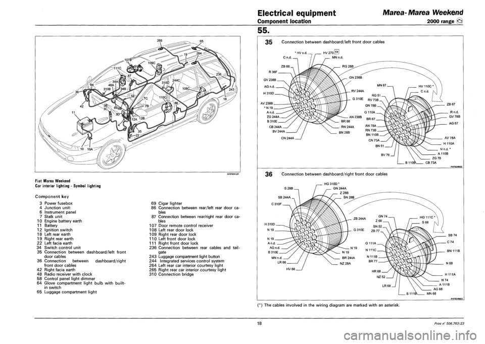
CAR INTERIOR LIGHTING - SYMBOL LIGHTING
Component key
3 Power fusebox
4 Junction unit:
6 Instrument panel
7 Stalk unit
10 Engine battery earth
11 Battery
12 Ignition switch
18 Left rear earth
19 Right rear earth
22 Left facia earth
34 Switch control unit
35 Connection between dashboard/left front
door cables
36 Connection between dashboard/right
front door cables
42 Right facia earth
48 Radio receiver with clock
58 Control panel light dimmer
64 Glove compartment light bulb with built-
in switch
65 Luggage compartment light
69 Cigar lighter
86 Connection between rear/left rear door ca
bles
87 Connection between rear/right rear door ca
bles
107 Door remote control receiver
108 Left rear door lock
109 Right rear door lock
110 Left front door lock
111 Right front door lock
236 Connection between rear cables and tail
gate
243 Luggage compartment light button
244 Integrated services control system
264 Left rear car interior courtesy light
265 Right rear car interior courtesy light
310 Connection bridge
Electrical equipment Marea-Marea Weekend
Component location 2000 range (j§)
55.
35 Connection between dashboard/left front door cables
P4F824N02
36 Connection between dashboard/right front door cables
P4F824N03
(*) The cables involved in the wiring diagram are marked with an asterisk.
18 Print n° 506.763/23
Page 206 of 330
Electrical equipment
Component location
Marea-Marea Weekend
2000 range ©
55.
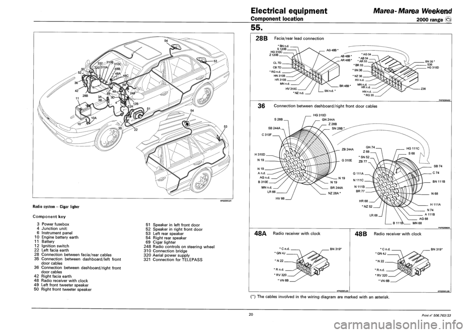
RADIO SYSTEM - CIGAR LIGHER
Component key
3 Power fusebox
4 Junction unit:
6 Instrument panel
10 Engine battery earth
11 Battery
12 Ignition switch
22 Left facia earth
28 Connection between facia/rear cables
35 Connection between dashboard/left front
door cables
36 Connection between dashboard/right front
door cables
42 Right facia earth
48 Radio receiver with clock
49 Left front tweeter speaker
50 Right front tweeter speaker
51 Speaker in left front door
52 Speaker in right front door
53 Left rear speaker
54 Right rear speaker
69 Cigar lighter
248 Radio controls on steering wheel
310 Connection bridge
320 Aerial power supply
321 Connection for TELEPASS
28B Facia/rear lead connection
* BN n.d. S 120B HG310C Z120B
AG 48B *
HV310C
* NZ n.d
AB48B* AB
AR48B* .AR
*BR53
*SN 36
BR 48B *
SN n.d.'
36 Connection between dashboard/right front door cables
S28B.
HG 310D
GN 244A
Z28B
N 19
A n.d
AG n.d
B310E
MN n.d.
LR 66
BN 111B
HV66
H 111A
A111B
AG 68
MN68
48A Radio receiver with clock
*N22
BN 319*
* R n.d
* RV 320
*VN 6B
48 B Radio receiver with clock
BN 319*
(*) The cables involved in the wiring diagram are marked with an asterisk.
20 Print n° 506.763/23
Page 208 of 330
P4F830N01
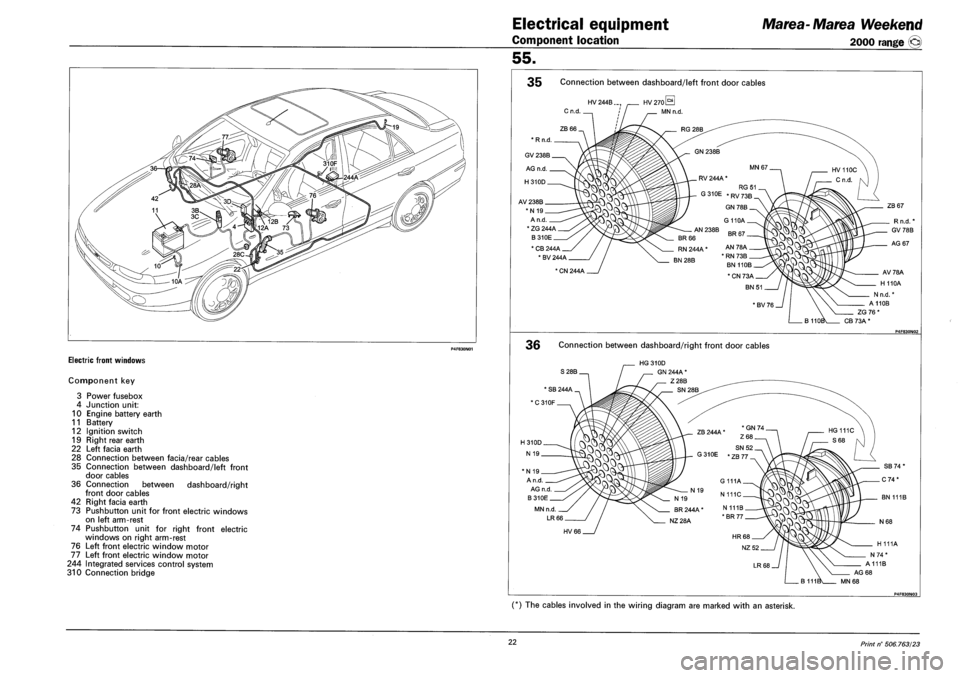
ELECTRIC FRONT WINDOWS
Component key
3 Power fusebox
4 Junction unit:
10 Engine battery earth
11 Battery
12 Ignition switch
19 Right rear earth
22 Left facia earth
28 Connection between facia/rear cables
35 Connection between dashboard/left front
door cables
36 Connection between dashboard/right
front door cables
42 Right facia earth
73 Pushbutton unit for front electric windows
on left arm-rest
74 Pushbutton unit for right front electric
windows on right arm-rest
76 Left front electric window motor
77 Left front electric window motor
244 Integrated services control system
310 Connection bridge
Electrical equipment Marea-Marea Weekend
Component location 2000 range @
55.
35 Connection between dashboard/left front door cables
- P4F830N02
36 Connection between dashboard/right front door cables
P4F830N03
(*) The cables involved in the wiring diagram are marked with an asterisk.
22 Print n° 506.763/23
Page 210 of 330
Electrical equipment
Component location
Marea-Marea Weekend
2000 range ®
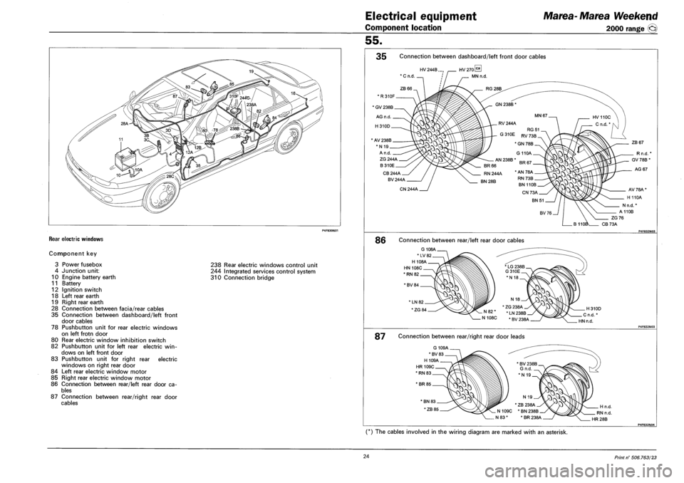
REAR ELECTRIC WINDOWS
Component key
3 Power fusebox
4 Junction unit:
10 Engine battery earth
11 Battery
12 Ignition switch
18 Left rear earth
19 Right rear earth
28 Connection between facia/rear cables
35 Connection between dashboard/left front
door cables
78 Pushbutton unit for rear electric windows
on left frotn door
80 Rear electric window inhibition switch
82 Pushbutton unit for left rear electric win
dows on left front door
83 Pushbutton unit for right rear electric
windows on right rear door
84 Left rear electric window motor
85 Right rear electric window motor
86 Connection between rear/left rear door ca
bles
87 Connection between rear/right rear door
cables
238 Rear electric windows control unit
244 Integrated services control system
310 Connection bridge
55.
35 Connection between dashboard/left front door cables
HV 244B.
ZB 67 * AV 238B
*N 19
A n.d.
ZG 244A
B310E
CB 244A
BV 244A
Rn.d.
GV 78B *
AG 67
CN 244A
86 Connection between rear/left rear door cables
G 108A
*LV82
H 108A
HN 108C
*RN82
*BV 84
H310D
C n.d. *
HN n.d.
87 Connection between rear/right rear door leads
G 109A
*BV83
H 109A
HR 109C
*RN83
*BR85
BN 83
*ZB 85 * ZB 238A
N109C *BN238B
N 83 * * BR 238A
H n.d.
RN n.d.
HR28B
(*) The cables involved in the wiring diagram are marked with an asterisk.
24 Print n° 506.763/23
Page 212 of 330
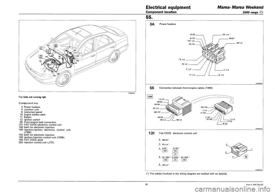
4F026ML01
FIAT CODE AND WARNING LIGHT
Component key
3 Power fusebox
4 Junction unit:
6 Instrument panel
10 Engine battery earth
11 Battery
12 Ignition switch
55 Front/engine lead connection
131 FIAT CODE electronic control unit
148 Earth for electronic injection
190 Injection/ignition electronic control unit
(1998)
193 Earth for electronic injection
195 Ignition/injection control unit (1596)
199 FIAT CODE aerial
333 Injection control unit (JTD)
Electrical equipment Marea-Marea Weekend
Component location 2000 range @
55.
3A Power fusebox
* R n.d. _
M n.d.
C
VN127
ARn.d.
P4F834IM02
55 Connection between front/engine cables (1998)
1998
4F026ML03
131 Fiat-CODE electronic control unit
MN 6A *
1998 JTD 1596
JL CBn.d. *
4F026ML04
(*) The cables involved in the wiring diagram are marked with an asterisk.
26 Print n° 506.763/23
Page 214 of 330
Electrical system
Component location
Marea-Marea Weekend
2000 range ©
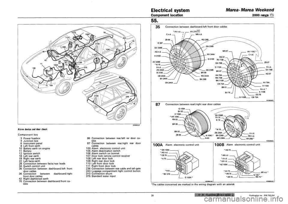
ALARM DEVICE AND DOOR CHECK
Component key
3 Power fusebox
4 Junction box
6 Instrument panel
8 Left front earth
10 Battery earth on engine
11 Battery
12 Ignition switch
18 Left rear earth
19 Right rear earth
22 Left facia earth
28 Connection between facia/rear leads
34 Switch control unit
35 Connection between dashboard/left front
door cables
36 Connection between dashboard/right
front door cables
42 Right dashborad earth
70 Connection between dashboard/front ca
bles
86 Connection between rear/left rer door ca
bles
87 Connection between rear/right rear door
cables
100 Alarm electronic control unit
105 Alarm deactivation switch
106 Alarm switch on bonnet
107 Door lock remote control receiver
108 Left rear door lock
109 Right rear door lock
110 Left front door lock
111 Right front door lock
236 Connection between rear cable and tail-gate
243 Luggage compartment light control button
310 Connection shunt
375 Standard tester input
55.
35 Connection between dashboard/left front door cables
'HVn.d.
Cn.d.
ZB67
ZG244A
B310E
CB244A
BV244A
Rn.d.
GV78B
AG 67
CN244A
87 Connection between rearl/right rear door cables
G 109A
BV83
H 109A
'HR109C
RN 83
BR 85
BN 83
ZB 85 Hn.d.
RN n.d.
HR 28B *
1 00A Alarm electronic control unit
' BV 375
G105A"
100B Alarm electronic control unit
*HG70_
'HN 70
*HR70
AR n.d. *
N 106* RN70'
*The cables concerned are marked in the wiring diagram with an asterisk
28 x" 00 -Supersedes previous version £ Publication no. 506.763/24
Page 216 of 330
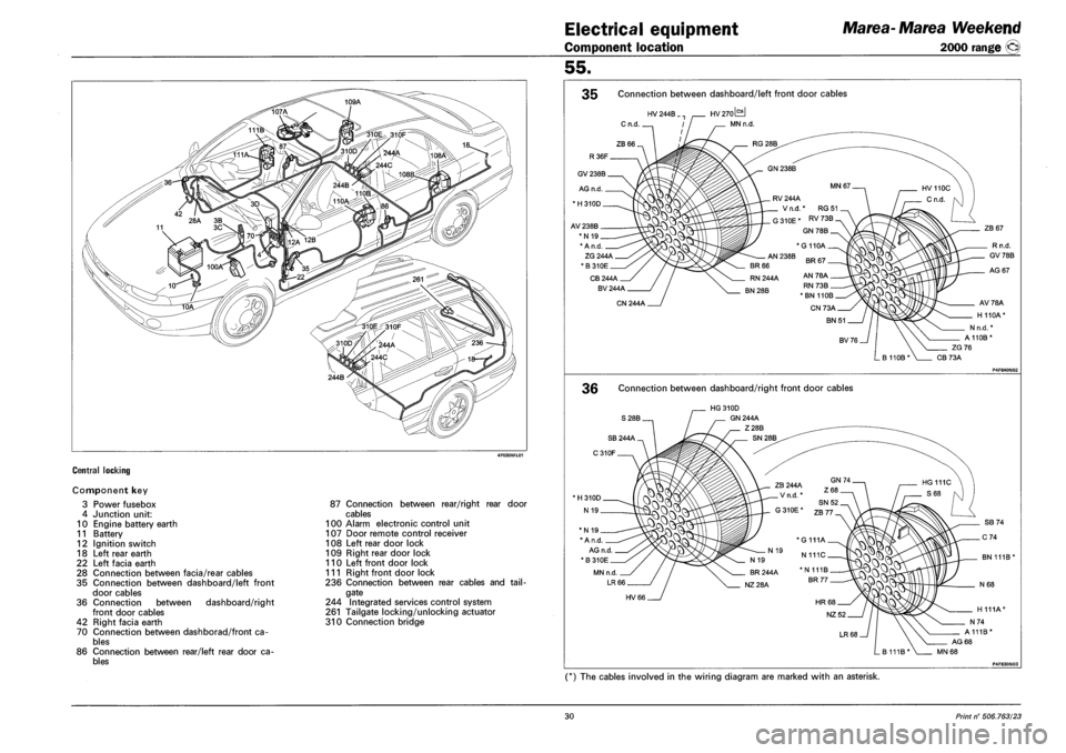
4F030ML01
CENTRAL LOCKING
Component key
3 Power fusebox
4 Junction unit:
10 Engine battery earth
11 Battery
12 Ignition switch
18 Left rear earth
22 Left facia earth
28 Connection between facia/rear cables
35 Connection between dashboard/left front
door cables
36 Connection between dashboard/right
front door cables
42 Right facia earth
70 Connection between dashborad/front ca
bles
86 Connection between rear/left rear door ca
bles
87 Connection between rear/right rear door
cables
100 Alarm electronic control unit
107 Door remote control receiver
108 Left rear door lock
109 Right rear door lock
110 Left front door lock
111 Right front door lock
236 Connection between rear cables and tail
gate
244 Integrated services control system
261 Tailgate locking/unlocking actuator
310 Connection bridge
Electrical equipment Marea-Marea Weekend
Component location 2000 range ©
55.
35 Connection between dashboard/left front door cables
36 Connection between dashboard/right front door cables
P4F830N03
(*) The cables involved in the wiring diagram are marked with an asterisk.
30 Print n° 506.763/23
Page 220 of 330
Electrical equipment
Component location
Marea- Marea Weekend
2000 range ©
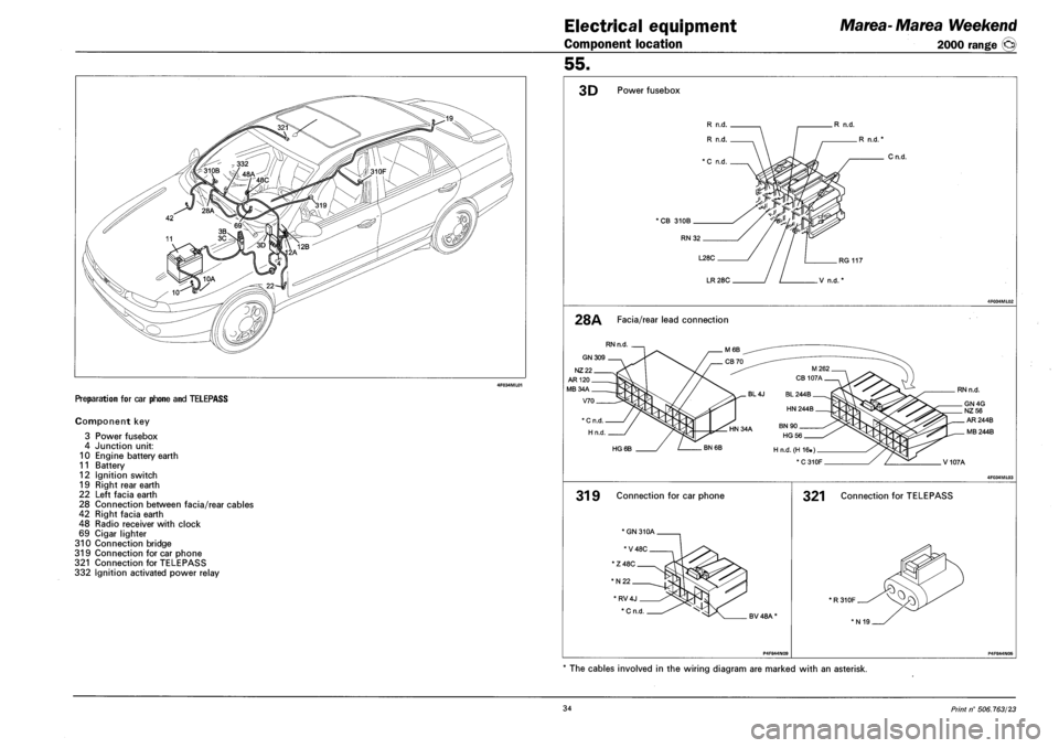
PREPARATION FOR CAR PHONE AND TELEPASS
Component key
3 Power fusebox
4 Junction unit:
10 Engine battery earth
11 Battery
12 Ignition switch
19 Right rear earth
22 Left facia earth
28 Connection between facia/rear cables
42 Right facia earth
48 Radio receiver with clock
69 Cigar lighter
310 Connection bridge
319 Connection for car phone
321 Connection for TELEPASS
332 Ignition activated power relay
55.
3D Power fusebox
R n.d.
R n.d. *
'CB 310B
RN32
Cn.d.
RG 117
LR 28C V n.d. *
28A Facia/rear lead connection
RN n.d
GN 309
NZ22
HG 6B
31 9 Connection for car phone
' RV4J
* C n.d BV 48A'
RN n.d.
GN4G NZ56
AR 244B
MB 244B
V107A
321 Connection for TELEPASS
*R310F
'N19
The cables involved in the wiring diagram are marked with an asterisk.
34 Print n° 506.763/23
Page 222 of 330
Electrical equipment
Component location
Marea-Marea Weekend
2000 range ©
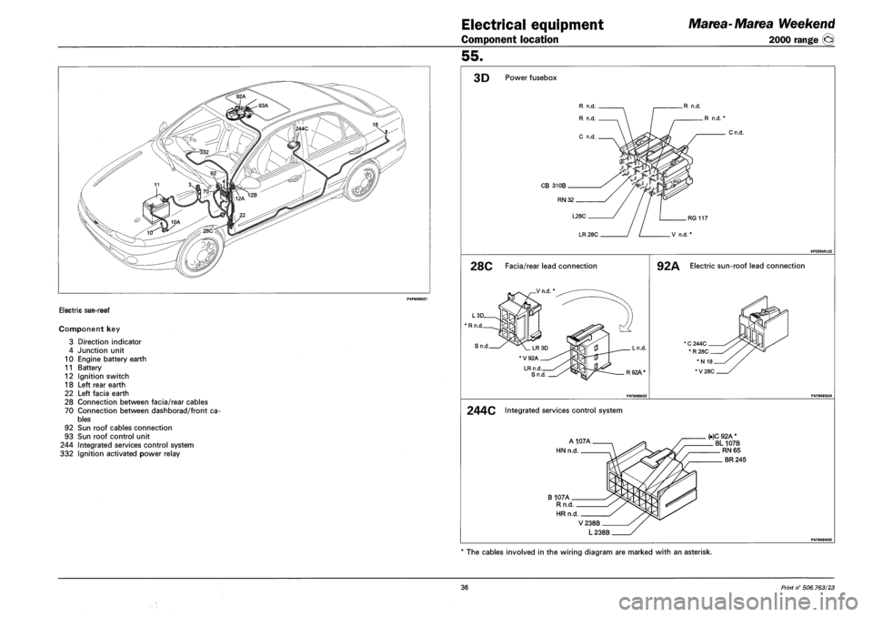
ELECTRIC SUN-ROOF
Component key
3 Direction indicator
4 Junction unit
10 Engine battery earth
11 Battery
12 Ignition switch
18 Left rear earth
22 Left facia earth
28 Connection between facia/rear cables
70 Connection between dashborad/front ca
bles
92 Sun roof cables connection
93 Sun roof control unit
244 Integrated services control system
332 Ignition activated power relay
55.
3D Power fusebox
R n.d.
R n.d.'
CB 310B
RN 32
Cn.d.
LR 28C
28C Facia/rear lead connection
Rn.d §
Sn.d.
LRn.d Sn.d
Ln.d.
R92A*
92A Electric sun-roof lead connection
244C Integrated services control system
A107A
HN n.d.
B 107A Rn.d
HRn.d.
(.)C 92A * BL 107B RN 65
BR 245
V238B
L238B
The cables involved in the wiring diagram are marked with an asterisk.
36 Print n° 506,763/23
Page 226 of 330
Electrical equipment
Component location
Marea- Marea Weekend
2000 range ©
55.
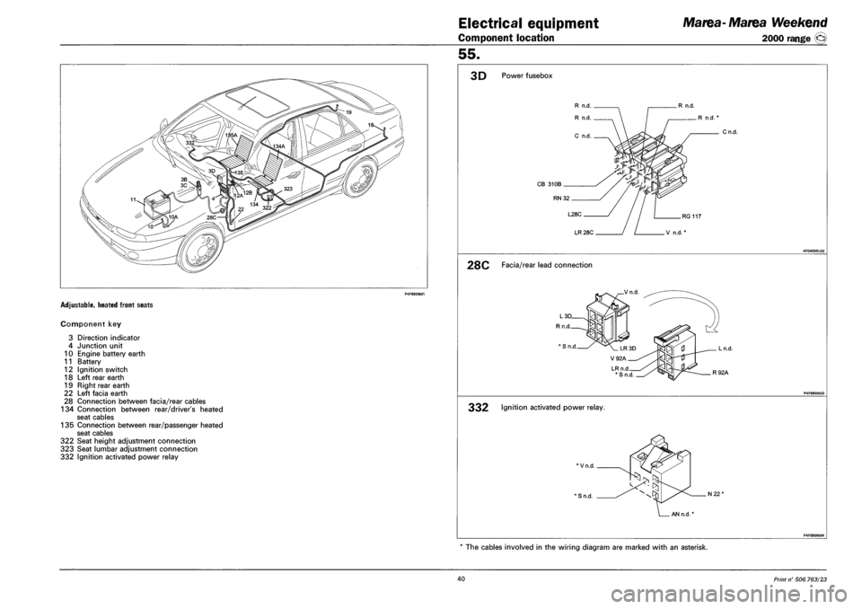
ADJUSTABLE, HEATED FRONT SEATS
Component key
3 Direction indicator
4 Junction unit
10 Engine battery earth
11 Battery
12 Ignition switch
18 Left rear earth
19 Right rear earth
22 Left facia earth
28 Connection between facia/rear cables
134 Connection between rear/driver's heated
seat cables
135 Connection between rear/passenger heated
seat cables
322 Seat height adjustment connection
323 Seat lumbar adjustment connection
332 Ignition activated power relay
3D Power fusebox
R n.d.
R n.d.
C n.d.
R n.d.
CB 31 OB .
RN 32.
L28C .
LR 28C
.R n.d.
Cn.d.
.RG 117
V n.d.
28C Facia/rear lead connection
_Vn.d
LRn.d *Sn.d
. Ln.d.
. R92A
332 Ignition activated power relay.
*Vn.d.
' S n.d. N22"
AN n.d.
P4F850N04
* The cables involved in the wiring diagram are marked with an asterisk.
40 Print n° 506.763/23