Injection FIAT MAREA 2001 1.G Owner's Manual
[x] Cancel search | Manufacturer: FIAT, Model Year: 2001, Model line: MAREA, Model: FIAT MAREA 2001 1.GPages: 330
Page 90 of 330
Fuel feed system
Engine Marea- Marea Weekend 9 ™
2000 range (Q)
10.
Control of idle speed
On the basis of signals from the rpm sensor and engine coolant temperature sensor, the injection control
unit controls the pressure governor and alters the injector control times to maintain idle speed stable at all
times.
Under certain conditions, the idle speed control unit also considers battery voltage.
Control of maximum speed limitation
According to rpm level, the injection control unit limits maximum speed by means of two types of inter
vention:
- as maximum speed approaches, it reduces the amount of fuel injected to reduce line pressure;
- when maximum speed is exceeded, it inhibits operation of the auxiliary pump and injectors.
Control of maximum torque limitation
On the basis of rpm level, the injection control unit computes limit torque and maximum permitted fume
index parameters on the basis of predefined, stored maps.
It then corrects the above parameters using engine coolant temperature and car speed data. The resulting
values are then used to modulate the amount of fuel to be injected by adjusting the pressure regulator and
injectors.
Control of fuel temperature
The injection control uint is kept constantly informed of fuel temperature by a sensor on the return mani
fold.
If fuel temperature exceeds a set value (about 110 °C), the control unit reduces line pressure by adjusting
the pressure governor, leaving injection times unaltered.
Control of coolant temperature
The injection control unit is constantly informed of coolant temperature by a sensor on the thermostat.
If engine coolant temperature or air conditioning fluid pressure exceeds certain levels, the control unit
performs the following actions:
- It reduces the amount of fuel injected by adjusting the pressure governor and injectors (power reduc
tion);
- it controls the engine radiator cooling fan.
Control of glow plugs
The injection control unit controls operation of the glow plug preheating control unit to bring the tem
perature in the combution chambers up to levels that promote fuel self-ignition and thus make start-up
easier.
The control unit controls the operation of the glow plug control unit for a certain time both before (pre
heating) and after (postheating) engine start-up and also controls activation of the warning light on the
control panel.
Preheating, postheating and glow plug warning light activation times vary according to engine coolant
temperature.
4 Publication no. 506.763/24
Page 91 of 330
![FIAT MAREA 2001 1.G Owners Manual Marea-Marea Weekend 9]
2000 range (j§)
I) JTD
Fuel feed system
Engine
10.
Exhaust fumes control
Through this function the injection control unit limits any exhaust fumes that could be produce FIAT MAREA 2001 1.G Owners Manual Marea-Marea Weekend 9]
2000 range (j§)
I) JTD
Fuel feed system
Engine
10.
Exhaust fumes control
Through this function the injection control unit limits any exhaust fumes that could be produce](/img/10/4653/w960_4653-90.png)
Marea-Marea Weekend 9]
2000 range (j§)
I) JTD
Fuel feed system
Engine
10.
Exhaust fumes control
Through this function the injection control unit limits any exhaust fumes that could be produced during
transition speeds.
To satisy these requirements the control unit processes the signals supplied by the accelerator pedal po
tentiometer, the rpm sensor and the air flow meter and controls the fuel pressure regulator and the injec
tors to meter the correct amount of fuel to inject.
Exhaust gas recirculation control
On the basis of the signals supplied by the rpm sensor, intake air quantity sensor, engine coolant tempe
rature sensor and accelerator pedal position sensor, the control unit calculates the operating times for the
EGR valve so that the exhaust gases are partly recirculated in certain engine operating conditions in line
with Euro 3 pollution control standards.
Air conditioning system engagement control
The injection control unit manages the operation of the air conditioning system compressor electro
magnet coupling following a logic aimed at preventing operating conditions that would adversely affect
engine performance.
- When the compressor is switched on the injection control unit increases the quantity of fuel during
idling to allow the engine to adjust to the increased power requirements and momentarily interrupts the
supply to the compressor in high engine power requirement conditions (strong acceleration).
Engine immobilizer function control
The system is equipped with an engine immobilizer function. This function is achieved through the pre
sence of a specific control unit (Fiat CODE), capable of conversing with the injection control unit and an
electronic key with a special transmitter for sending a recognition code.
Each time the key is turned to the OFF position, the Fiat CODE system completely deactivates the injecti
on control unit.
When the key is turned to the ON position the following operations take place, in order:
1. the injection control unit (whose memory contains a secret code) sends the Fiat CODE control unit a
request to send the secret code to deactivate the immobilizer functions;
2. the Fiat CODE control unit responds by only sending the secret code after, in turn, having received the
recognition code transmitted by the ignition key;
3. the recognition of the secret code allows the deactivation of the injection control unit immobilizer func
tion and its normal operation.
Autodiagnosis
The complete electronic fault diagnosis of the injection system is carried out by connecting the special
equipment (EXAMINER or EXAMINER PLUS) to the standardized diagnostic socket (EOBD).
The system is also equipped with a self-diagnostic function which recognizes, memorizes and signals any
faults.
If a fault is detected in the sensors or actuators, the recovery strategy is immediately activated in order to
ensure that the engine functions at an acceptable level. The vehicle can be driven to a service centre for
the appropriate repairs to be carried out.
Copyright by Fiat Auto 5
Page 92 of 330
Fuel feed system
Engine Marea- Marea Weekend © ™
2000 range @
10.
The control unit autodiagnostic system checks the signals coming from the sensors and compares them
with the figures allowed:
- signalling faults during starting
- warning light on for 4 seconds indicates test stage
- warning light off after 4 seconds indicates no fault with components that could alter the pollution con
trol standard figures
- warning light on after 4 seconds indicates fault.
- signalling faults during operation
- warning light on indicates fault
- warning light off indicates no fault with components that could alter the pollution control standard fig
ures.
- recovery
- from time to time, the control unit defines the type of recovery according to the components which are
faulty
- the recovery parameters are managed by components which are not faulty.
Control of cylinder balancing during idling
According to the signals coming from the sensors, the injection control unit controls the idle speed torque,
altering the injector operating times.
Control of irregular operation
Depending on the signals coming from the sensors, the injection control unit corrects the amount of fuel
to be injected in order to improve driveability and reduce jerking whilst driving.
The correction is achieved through the fuel pressure regulator and by varying the injector operating times.
Control of electrical balance
According to the battery voltage, the injection control unit alters the idle speed, to guarantee a sufficient
current supply from the alternator in situations where the consumers are absorbing a great deal of power.
The variation in the idle speed is achived by regulating the fuel pressure and altering the injector operat
ing times.
VGT variable geometry turbocharger control (1910 JTD 110 CV)
The injection control unit processes the signal coming from the supercharging sensor, at the various en
gine operating speeds, and determines the quantity of fuel to be injected, acting on the fuel pressure
regulator and the injector opening times.
In addition, through the solenoid valve, the control unit regulates the geometry of the turbine in order to
ensure optimum performance in all operating conditions.
Turbocharger waste gate valve control (1910 JTD 100 CV)
At the various engine operating speeds, the injection control unit processes the signal coming from the
supercharging sensor and determines the amount of fuel to inject, acting on the fuel pressure regulator
and the injector opening times.
In addition, the control unit controls the opening of the turbocharger waste gate valve, via the solenoid
valve, in order to ensure excellent performance in all operating conditions.
Control of throttle closing when engine is switched off
When the engine is switched off (ignition key in OFF position) the injection control unit closes the throt
tle valve located on the air intake duct via the special solenoid valve.
This action makes it possible to limit the tiresome shuddering of the engine whilst it is switching off.
6 .i. V!-01-.Cancelftand replaces Print n° 506.763/25
Page 93 of 330
Marea- Marea Weekend 9 ™
2000 range ©
Engine
Fuel feed system
10.
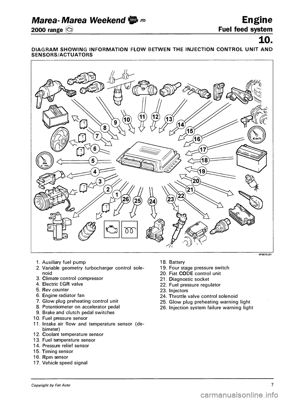
DIAGRAM SHOWING INFORMATION FLOW BETWEN THE INJECTION CONTROL UNIT AND
SENSORS/ACTUATORS
1. Auxiliary fuel pump
2. Variable geometry turbocharger control sole
noid
3. Climate control compressor
4. Electric EGR valve
5. Rev counter
6. Engine radiator fan
7. Glow plug preheating control unit
8. Potentiometer on accelerator pedal
9. Brake and clutch pedal switches
10. Fuel pressure sensor
11. Intake air flow and temperature sensor (de-
bimeter)
12. Coolant temperature sensor
13. Fuel temperature sensor
14. Pressure relief sensor
15. Timing sensor
16. Rpm sensor
17. Vehicle speed signal
18. Battery
19. Four stage pressure switch
20. Fiat CODE control unit
21. Diagnostic socket
22. Fuel pressure regulator
23. Injectors
24. Throttle valve control solenoid
25. Glow plug preheating warning light
26. Injection system failure warning light
Copyright by Fiat Auto 1
Page 94 of 330
Engine
Fuel feed system
Marea- Marea Weekend 9 ™
2000 range O
10.
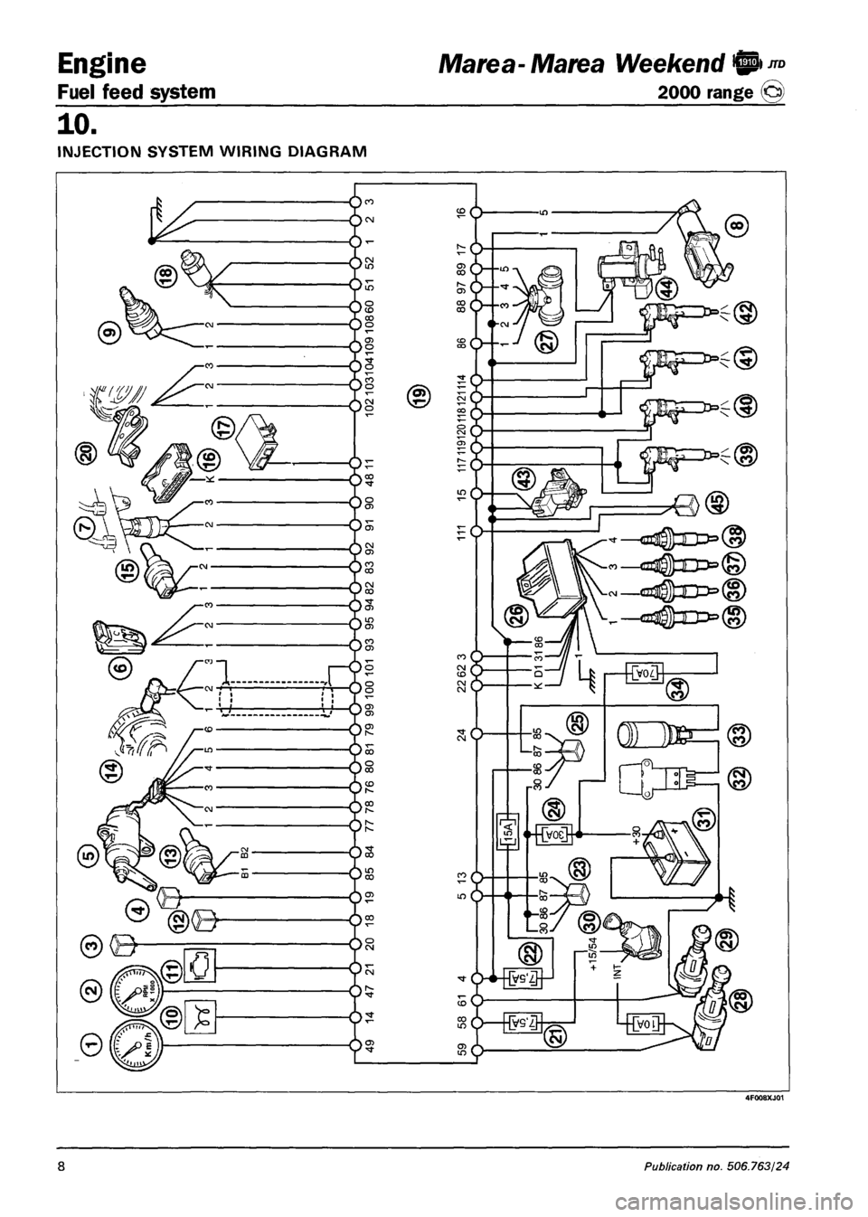
INJECTION SYSTEM WIRING DIAGRAM
4F008XJ01
8 Publication no. 506.763/24
Page 95 of 330
Marea- Marea Weekend 9 ™
2000 range ©) Fuel feed system
Engine
10.
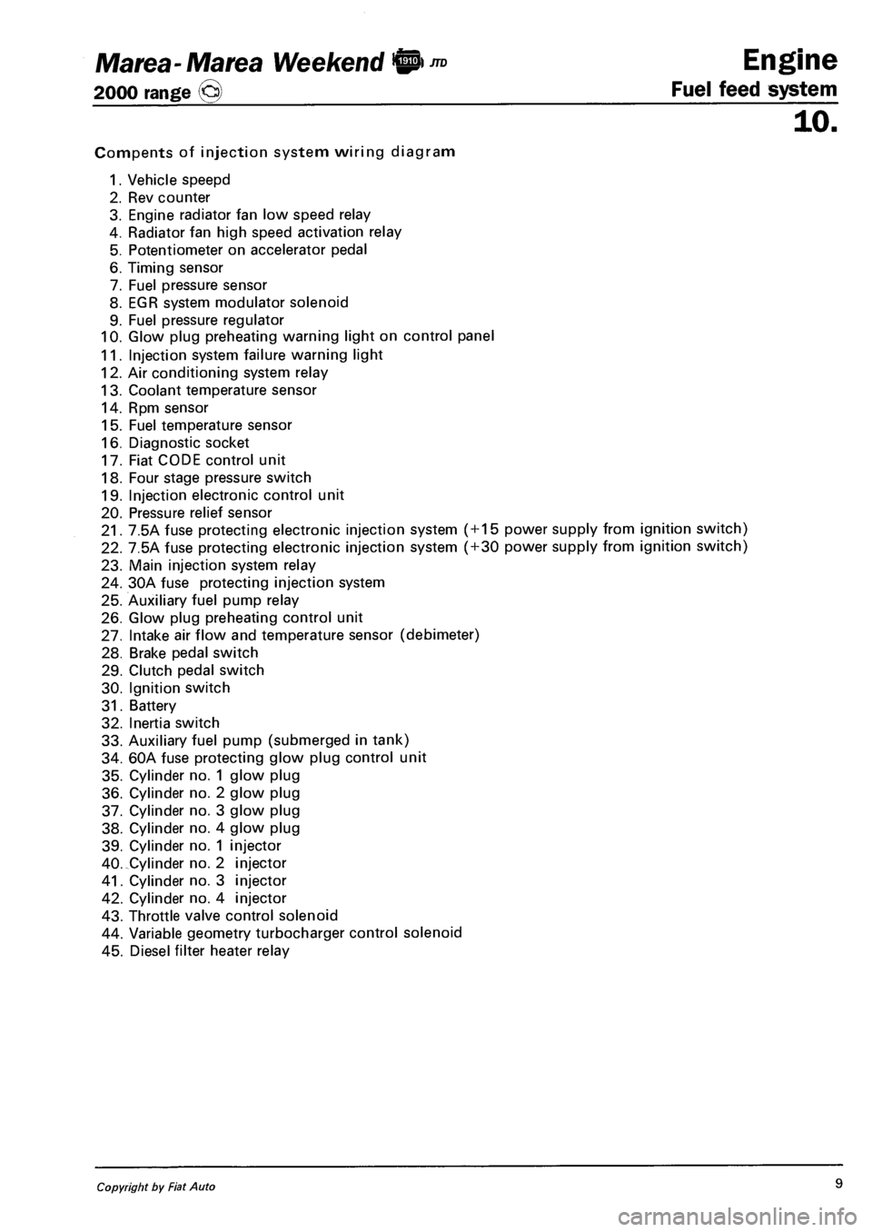
Compents of injection system wiring diagram
1. Vehicle speepd
2. Rev counter
3. Engine radiator fan low speed relay
4. Radiator fan high speed activation relay
5. Potentiometer on accelerator pedal
6. Timing sensor
7. Fuel pressure sensor
8. EGR system modulator solenoid
9. Fuel pressure regulator
10. Glow plug preheating warning light on control panel
11. Injection system failure warning light
12. Air conditioning system relay
13. Coolant temperature sensor
14. Rpm sensor
15. Fuel temperature sensor
16. Diagnostic socket
17. Fiat CODE control unit
18. Four stage pressure switch
19. Injection electronic control unit
20. Pressure relief sensor
21. 7.5A fuse protecting electronic injection system ( + 15 power supply from ignition switch)
22. 7.5A fuse protecting electronic injection system ( + 30 power supply from ignition switch)
23. Main injection system relay
24. 30A fuse protecting injection system
25. Auxiliary fuel pump relay
26. Glow plug preheating control unit
27. Intake air flow and temperature sensor (debimeter)
28. Brake pedal switch
29. Clutch pedal switch
30. Ignition switch
31. Battery
32. Inertia switch
33. Auxiliary fuel pump (submerged in tank)
34. 60A fuse protecting glow plug control unit
35. Cylinder no. 1 glow plug
36. Cylinder no. 2 glow plug
37. Cylinder no. 3 glow plug
38. Cylinder no. 4 glow plug
39. Cylinder no. 1 injector
40. Cylinder no. 2 injector
41. Cylinder no. 3 injector
42. Cylinder no. 4 injector
43. Throttle valve control solenoid
44. Variable geometry turbocharger control solenoid
45. Diesel filter heater relay
Copyright by Fiat Auto 9
Page 96 of 330
Engine Marea- Marea Weekend 9 ™
Fuel feed system 2000 range @
10.
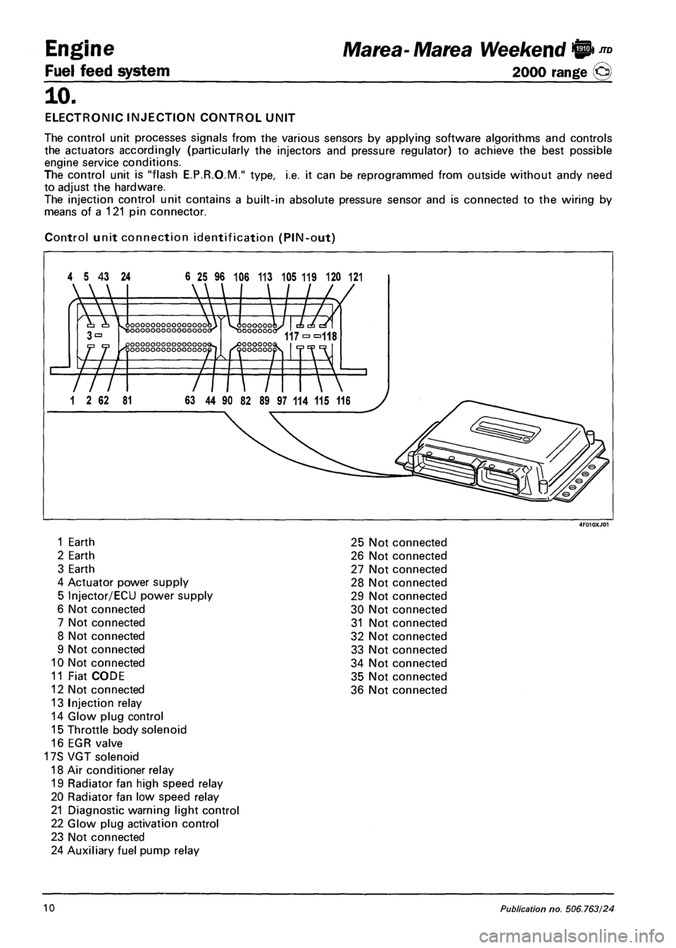
ELECTRONIC INJECTION CONTROL UNIT
The control unit processes signals from the various sensors by applying software algorithms and controls
the actuators accordingly (particularly the injectors and pressure regulator) to achieve the best possible
engine service conditions.
The control unit is "flash E.P.R.O.M." type, i.e. it can be reprogrammed from outside without andy need
to adjust the hardware.
The injection control unit contains a built-in absolute pressure sensor and is connected to the wiring by
means of a 121 pin connector.
Control unit connection identification (PIN-out)
4 5 43 24 6 25 96 106 113 105 119 120 121
1 Earth 25 Not connected
2 Earth 26 Not connected
3 Earth 27 Not connected
4 Actuator power supply 28 Not connected
5 Injector/ECU power supply 29 Not connected
6 Not connected 30 Not connected
7 Not connected 31 Not connected
8 Not connected 32 Not connected
9 Not connected 33 Not connected
10 Not connected 34 Not connected
11 Fiat CODE 35 Not connected
12 Not connected 36 Not connected
13 Injection relay
14 Glow plug control
15 Throttle body solenoid
16 EGR valve
17S VGT solenoid
18 Air conditioner relay
19 Radiator fan high speed relay
20 Radiator fan low speed relay
21 Diagnostic warning light control
22 Glow plug activation control
23 Not connected
24 Auxiliary fuel pump relay
10 Publication no. 506.763/24
Page 98 of 330
Engine
Fuel feed system
10.
4F012XJ03
Marea- Matea Weekend 9 ™
2000 range (Q)
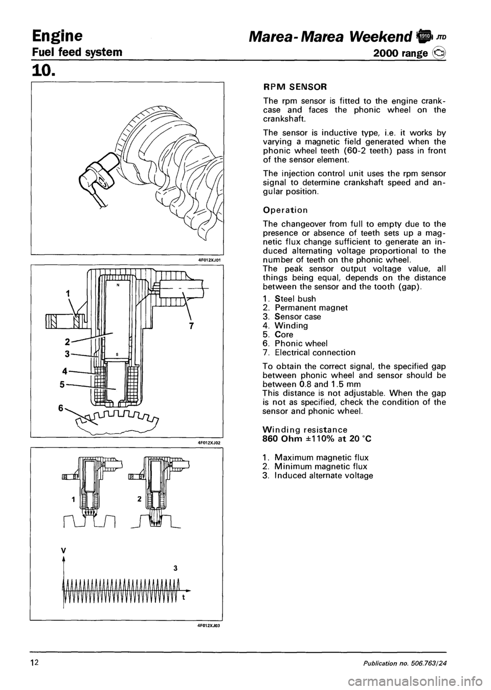
RPM SENSOR
The rpm sensor is fitted to the engine crank-
case and faces the phonic wheel on the
crankshaft.
The sensor is inductive type, i.e. it works by
varying a magnetic field generated when the
phonic wheel teeth (60-2 teeth) pass in front
of the sensor element.
The injection control unit uses the rpm sensor
signal to determine crankshaft speed and an
gular position.
Operation
The changeover from full to empty due to the
presence or absence of teeth sets up a mag
netic flux change sufficient to generate an in
duced alternating voltage proportional to the
number of teeth on the phonic wheel.
The peak sensor output voltage value, all
things being equal, depends on the distance
between the sensor and the tooth (gap).
1. Steel bush
2. Permanent magnet
3. Sensor case
4. Winding
5. Core
6. Phonic wheel
7. Electrical connection
To obtain the correct signal, the specified gap
between phonic wheel and sensor should be
between 0.8 and 1.5 mm
This distance is not adjustable. When the gap
is not as specified, check the condition of the
sensor and phonic wheel.
Winding resistance
860 Ohm ±110% at 20 °C
1. Maximum magnetic flux
2. Minimum magnetic flux
3. Induced alternate voltage
12 Publication no, 506.763/24
Page 99 of 330
Marea- Marea Weekend 9"°
2000 range ©
Engine
Fuel feed system
10.
TIMING SENSOR
The Hall effect sensor is fitted to the cylinder head and faces the camshaft pulley.
An opening on the pulley allows the timing sensor to detect the engine timing position and indicate it to
the injection control unit.
The injection control unit uses the timing sensor signal to detect TDC at the end of compression.
Operation
A semi-condulator layer, through which a current passes, immersed in a magnetic field (lines of force per
pendicular to the direction of the current), produces a difference in power, known as Hall voltage.
If the intensity of the current remains constant, the voltage produced only depends on the intensity of the
magnetic field. The intensity of the field can simply be altered periodically to produce a modulated electri
cal signal. Signal frequency is proportional to the speed with which the magnetic field changes.
To achieve this change, the sensor is crossed by a metal ring (inner part of the pulley) with an opening.
When it moves, the metal part of the ring covers the sensor to magnetic field and the output signal is
therefore low; Conversely, the sensor generates a high signal at the opening when the magnetic field is
present.
This signal, together with the rpm and TDC signals, allows the injection control unit to identify piston po
sition and determine injection point.
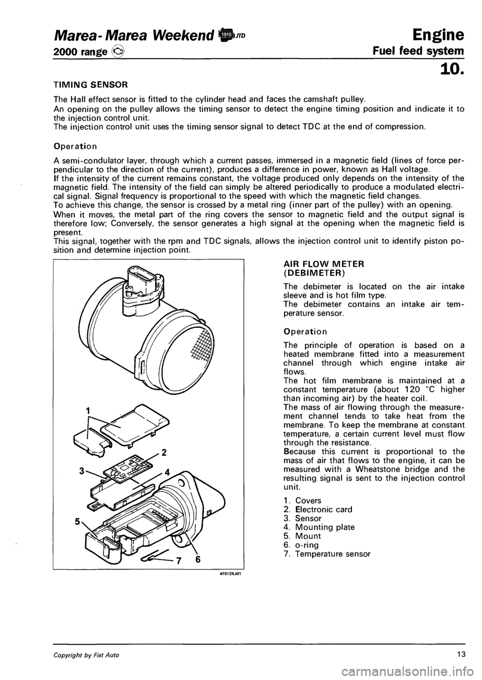
AIR FLOW METER
(DEBIMETER)
The debimeter is located on the air intake
sleeve and is hot film type.
The debimeter contains an intake air tem
perature sensor.
Operation
The principle of operation is based on a
heated membrane fitted into a measurement
channel through which engine intake air
flows.
The hot film membrane is maintained at a
constant temperature (about 120 °C higher
than incoming air) by the heater coil.
The mass of air flowing through the measure
ment channel tends to take heat from the
membrane. To keep the membrane at constant
temperature, a certain current level must flow
through the resistance.
Because this current is proportional to the
mass of air that flows to the engine, it can be
measured with a Wheatstone bridge and the
resulting signal is sent to the injection control
unit.
1. Covers
2. Electronic card
3. Sensor
4. Mounting plate
5. Mount
6. o-ring
7. Temperature sensor
Copyright by Fiat Auto 13
Page 100 of 330
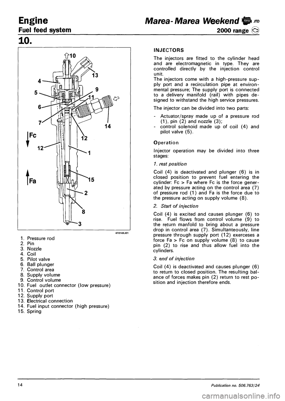
Engine
Fuel feed system
10.
1. Pressure rod
2. Pin
3. Nozzle
4. Coil
5. Pilot valve
6. Ball plunger
7. Control area
8. Supply volume
9. Control volume
10. Fuel outlet connector (low pressure)
11. Control port
12. Supply port
13. Electrical connection
14. Fuel input connector (high pressure)
15. Spring
Marea- Marea Weekend 9 ™
2000 range (Q)
INJECTORS
The injectors are fitted to the cylinder head
and are electromagnetic in type. They are
controlled directly by the injection control
unit.
The injectors come with a high-pressure sup
ply port and a recirculation pipe at environ
mental pressure; The supply port is connected
to a delivery manifold (rail) with pipes de
signed to withstand the high service pressures.
The injector can be divided into two parts:
- Actuator/spray made up of a pressure rod
(1), pin (2) and nozzle (3);
- control solenoid made up of coil (4) and
pilot valve (5).
Operation
Injector operation may be divided into three
stages:
1. rest position
Coil (4) is deactivated and plunger (6) is in
closed position to prevent fuel entering the
cylinder: Fc > Fa where Fc is the force gener
ated by pressure acting on the control area (7)
of pressure rod (1) and Fa is the force due to
the pressure acting on supply volume (8).
2. Start of injection
Coil (4) is excited and causes plunger (6) to
rise. Fuel flows from control volume (9) to
the return manfold to bring about a pressure
drop in control area (7). Simultanteously, line
pressure through supply port (12) exerceses a
force Fa > Fc on supply volume (8) to cause
pin (2) to rise and thus allow fuel into the
cylinders.
3. end of injection
Coil (4) is deactivated and causes plunger (6)
to return to closed position. The resulting bal
ance of forces makes pin (2) return to rest po
sition and injection therefore ends.
14 Publication no. 506.763/24