connector I FIAT MAREA 2001 1.G Owner's Manual
[x] Cancel search | Manufacturer: FIAT, Model Year: 2001, Model line: MAREA, Model: FIAT MAREA 2001 1.GPages: 330
Page 136 of 330
Electrical system
Junction unit
Marea- Marea Weekend
2000 range ©
55. 55.
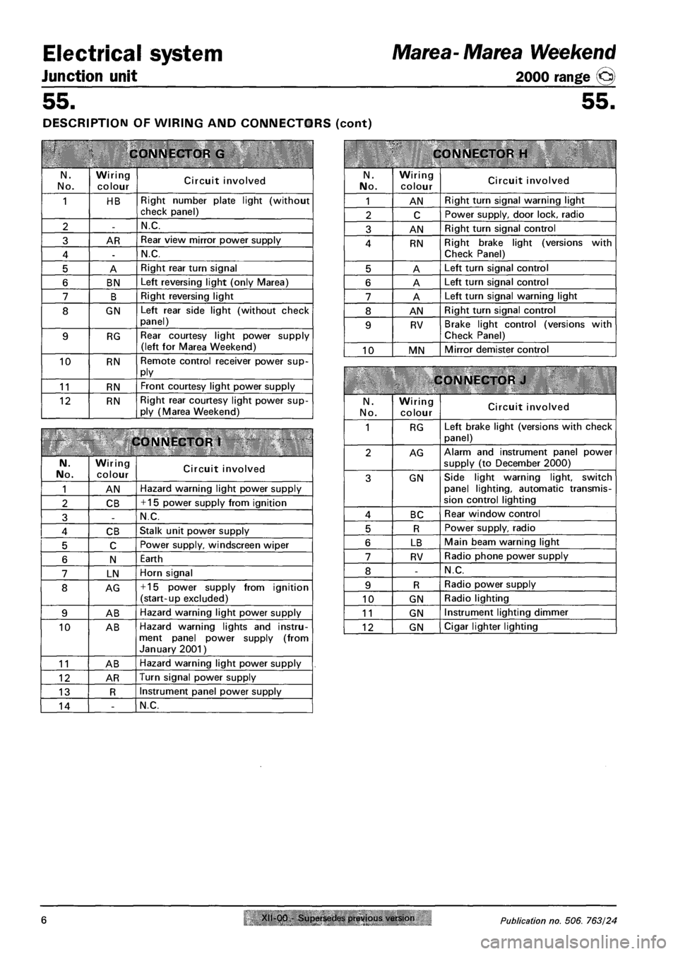
DESCRIPTION OF WIRING AND CONNECTORS (cont)
CONNECTOR G
N.
No.
Wiring
colour Circuit involved
1 HB Right number plate light (without check panel)
2 -N.C.
3 AR Rear view mirror power supply
4 -N.C.
5 A Right rear turn signal
6 BN Left reversing light (only Marea)
7 B Right reversing light
8 GN Left rear side light (without check panel)
9 RG Rear courtesy light power supply (left for Marea Weekend)
10 RN Remote control receiver power supply
11 RN Front courtesy light power supply
12 RN Right rear courtesy light power supply (Marea Weekend)
CONNECTOR 1
N. No. Wiring
colour Circuit involved
1 AN Hazard warning light power supply
2 CB + 15 power supply from ignition
3 -N.C.
4 CB Stalk unit power supply
5 C Power supply, windscreen wiper
6 N Earth
7 LN Horn signal
8 AG + 15 power supply from ignition (start-up excluded)
9 AB Hazard warning light power supply
10 AB Hazard warning lights and instrument panel power supply (from January 2001)
11 AB Hazard warning light power supply
12 AR Turn signal power supply
13 R Instrument panel power supply
14 -N.C.
CONNECTOR H
N.
No.
Wiring
colour Circuit involved
1 AN Right turn signal warning light
2 C Power supply, door lock, radio
3 AN Right turn signal control
4 RN Right brake light (versions with Check Panel)
5 A Left turn signal control
6 A Left turn signal control
7 A Left turn signal warning light
8 AN Right turn signal control
9 RV Brake light control (versions with
Check Panel)
10 MN Mirror demister control
CONNECTOR J
N.
No.
Wiring colour Circuit involved
1 RG Left brake light (versions with check
panel)
2 AG Alarm and instrument panel power
supply (to December 2000)
3 GN Side light warning light, switch panel lighting, automatic transmission control lighting
4 BC Rear window control
5 R Power supply, radio
6 LB Main beam warning light
7 RV Radio phone power supply
8 -N.C.
9 R Radio power supply
10 GN Radio lighting
11 GN Instrument lighting dimmer
12 GN Cigar lighter lighting
6 Publication no. 506. 763/24
Page 138 of 330
Electrical system
Protection and security devices
Marea-Marea Weekend
2000 range Q
55.
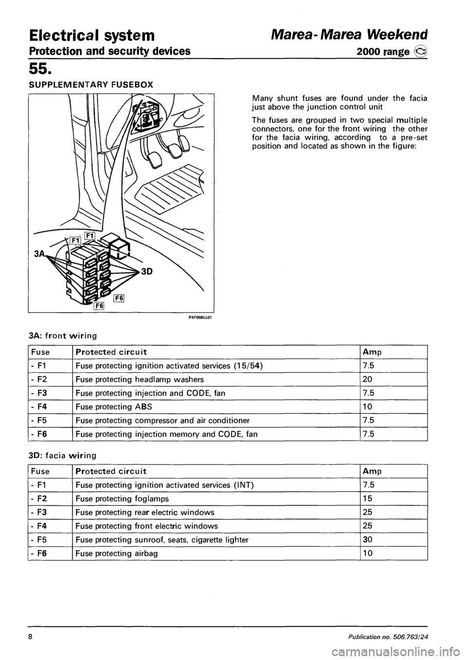
SUPPLEMENTARY FUSEBOX
Many shunt fuses are found under the facia
just above the junction control unit
The fuses are grouped in two special multiple
connectors, one for the front wiring the other
for the facia wiring, according to a pre-set
position and located as shown in the figure:
3A: front wiring
Fuse Protected circuit Amp
- F1 Fuse protecting ignition activated services (15/54) 7.5
- F2 Fuse protecting headlamp washers 20
- F3 Fuse protecting injection and CODE, fan 7.5
- F4 Fuse protecting ABS 10
- F5 Fuse protecting compressor and air conditioner 7.5
- F6 Fuse protecting injection memory and CODE, fan 7.5
3D: facia wiring
Fuse Protected circuit Amp
- F1 Fuse protecting ignition activated services (INT) 7.5
- F2 Fuse protecting foglamps 15
- F3 Fuse protecting rear electric windows 25
- F4 Fuse protecting front electric windows 25
- F5 Fuse protecting sunroof, seats, cigarette lighter 30
- F6 Fuse protecting airbag 10
8 Publication no. 506.763/24
Page 143 of 330
Marea- Marea Weekend
2000 range ©
Electrical equipment
Control module
55.
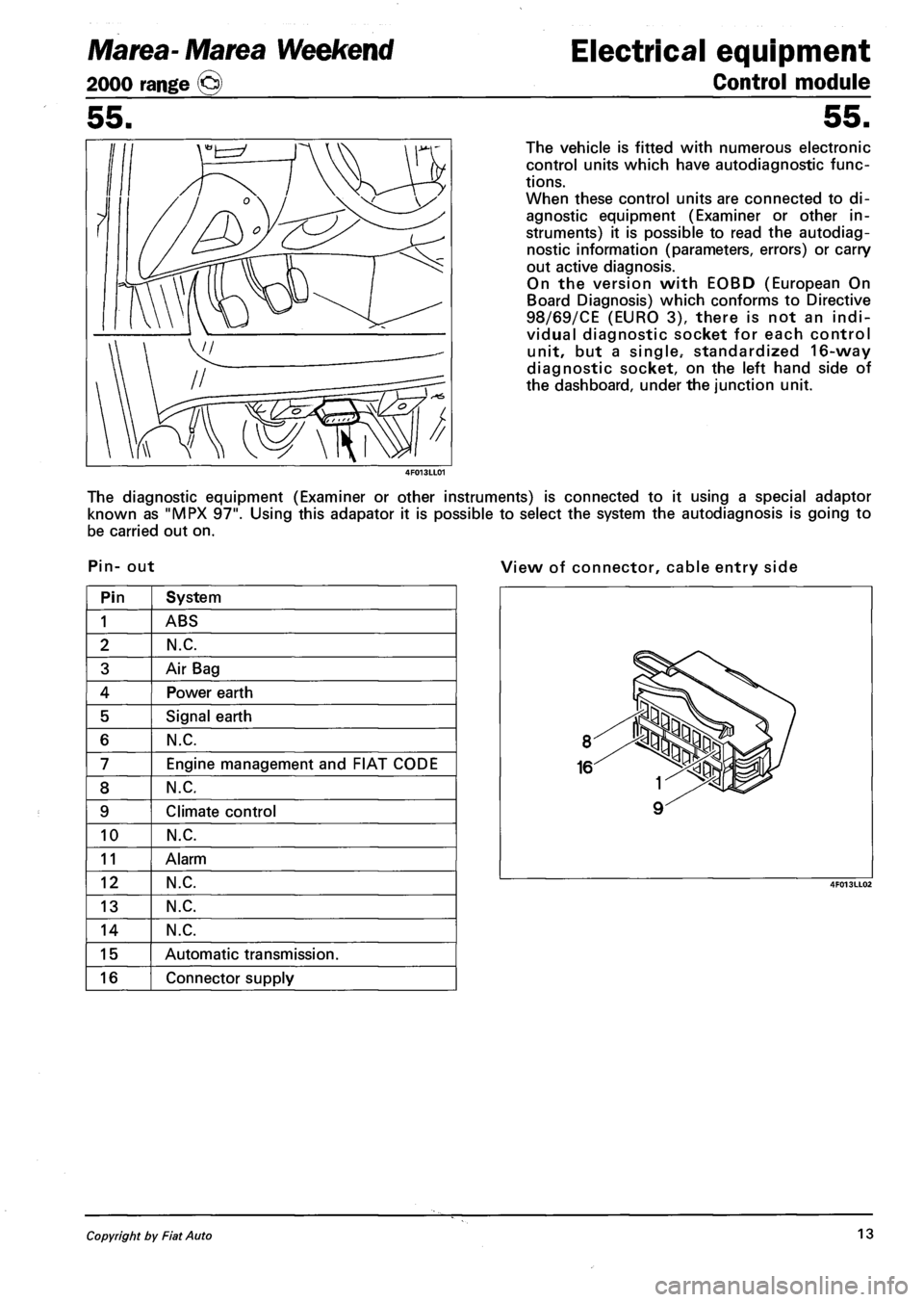
The vehicle is fitted with numerous electronic
control units which have autodiagnostic func
tions.
When these control units are connected to di
agnostic equipment (Examiner or other in
struments) it is possible to read the autodiag
nostic information (parameters, errors) or carry
out active diagnosis.
On the version with EOBD (European On
Board Diagnosis) which conforms to Directive
98/69/CE (EURO 3), there is not an indi
vidual diagnostic socket for each control
unit, but a single.- standardized 16-way
diagnostic socket, on the left hand side of
the dashboard, under the junction unit.
The diagnostic equipment (Examiner or other instruments) is connected to it using a special adaptor
known as "MPX 97". Using this adapator it is possible to select the system the autodiagnosis is going to
be carried out on.
Pin- out View of connector, cable entry side
Pin System
1 ABS
2 N.C.
3 Air Bag
4 Power earth
5 Signal earth
6 N.C.
7 Engine management and FIAT CODE
8 N.C.
9 Climate control
10 N.C.
11 Alarm
12 N.C.
13 N.C.
14 N.C.
15 Automatic transmission.
16 Connector supply
Copyright by Fiat Auto 13
Page 146 of 330
Electrical equipment
Instrument panel
Marea- Marea Weekend
2000 range ©
55.
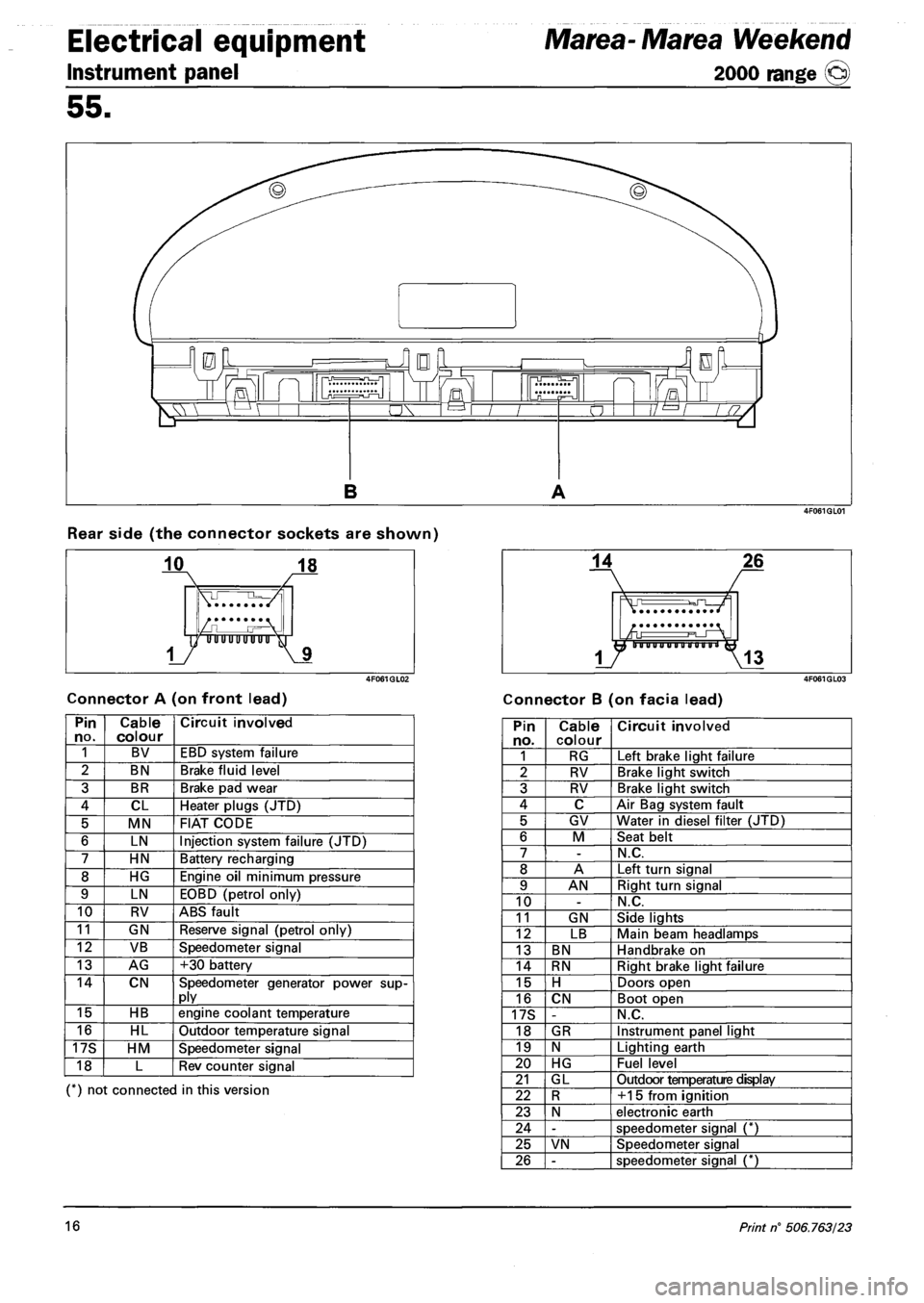
Rear side (the connector sockets are shown)
Connector A (on front lead) Connector B (on facia lead)
Pin no. Cable colour Circuit involved
1 BV EBD system failure
2 BN Brake fluid level
3 BR Brake pad wear
4 CL Heater plugs (JTD)
5 MN FIAT CODE
6 LN Injection system failure (JTD)
7 HN Battery recharging
8 HG Engine oil minimum pressure
9 LN EOBD (petrol only)
10 RV ABS fault
11 GN Reserve signal (petrol only)
12 VB Speedometer signal
13 AG +30 battery
14 CN Speedometer generator power supply
15 HB engine coolant temperature
16 HL Outdoor temperature signal
17S HM Speedometer signal
18 L Rev counter signal
(*) not connected in this version
Pin no. Cable colour Circuit involved
1 RG Left brake light failure
2 RV Brake light switch
3 RV Brake light switch
4 C Air Bag system fault
5 GV Water in diesel filter (JTD)
6 M Seat belt
7 -N.C.
8 A Left turn signal
9 AN Right turn signal
10 -N.C.
11 GN Side lights
12 LB Main beam headlamps
13 BN Handbrake on
14 RN Right brake light failure
15 H Doors open
16 CN Boot open
17S -N.C.
18 GR Instrument panel light
19 N Lighting earth
20 HG Fuel level
21 GL Outdoor temperature display
22 R +15 from ignition
23 N electronic earth
24 -speedometer signal (*)
25 VN Speedometer signal
26 -speedometer signal (*)
16 Print n° 506.763/23
Page 148 of 330
Electrical equipment
Control module
Marea- Marea Weekend
2000 range ©
55.
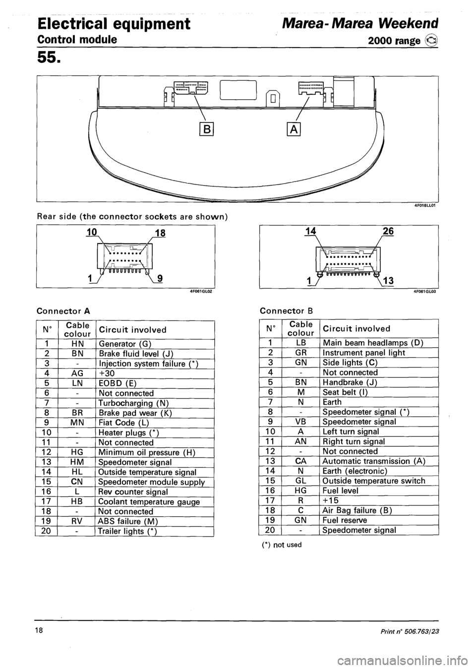
Rear side (the connector sockets are shown)
Connector A Connector B
N° Cable
colour Circuit involved
1 HN Generator (G)
2 BN Brake fluid level (J)
3 -Injection system failure (*)
4 AG +30
5 LN EOBD (E)
6 -Not connected
7 -Turbocharging (N)
8 BR Brake pad wear (K)
9 MN Fiat Code (L)
10 -Heater plugs (*)
11 -Not connected
12 HG Minimum oil pressure (H)
13 HM Speedometer signal
14 HL Outside temperature signal
15 CN Speedometer module supply
16 L Rev counter signal
17 HB Coolant temperature gauge
18 -Not connected
19 RV ABS failure (M)
20 -Trailer lights (*)
N° Cable
colour Circuit involved
1 LB Main beam headlamps (D)
2 GR Instrument panel light
3 GN Side lights (C)
4 -Not connected
5 BN Handbrake (J)
6 M Seat belt (I)
7 N Earth
8 -Speedometer signal (*)
9 VB Speedometer signal
10 A Left turn signal
11 AN Right turn signal
12 -Not connected
13 CA Automatic transmission (A)
14 N Earth (electronic)
15 GL Outside temperature switch
16 HG Fuel level
17 R + 15
18 C Air Bag failure (B)
19 GN Fuel reserve
20 -Speedometer signal
(*) not used
18 Print n° 506.763/23
Page 151 of 330
Marea- Marea Weekend Electrical system
2000 range @ Radio System
55.
TECHNICAL DATA
Radio power (H4 and H3 versions)
- 4 x 15W (with standard sound system made up of mid-woofer + tweeter and full range speakers).
Radio power (version M2)
- 2x15W (with standard sound system made up of mid-woofer + tweeter speakers).
- 4 x 5W (with optional 4-channel speaker system that can be installed by After Market).
WARNING The standard system is 2 x 15W, If a 2 x 15W system is fitted, an adaptor is fitted be
tween radio and wiring.
Fuse
The radio is fitted with a 10A fuse (D). (5A for the M2 version)
.Li.
3 6
2 5
B I M 5i I
T^l A 4| 6| |
I I I
2| 4| | |
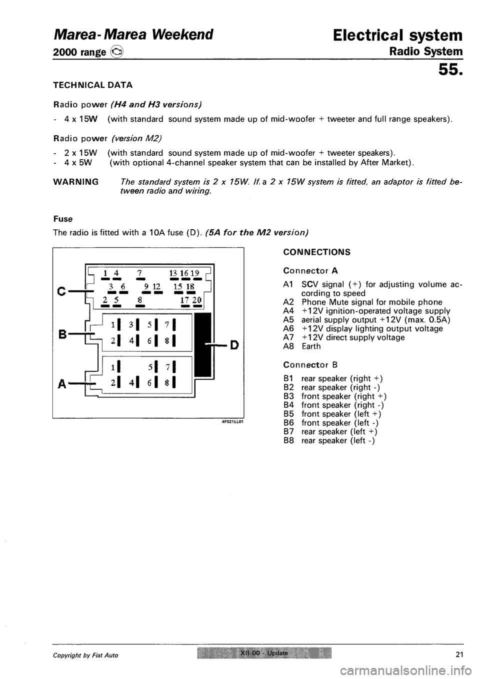
CONNECTIONS
Connector A
A1 SCV signal ( + ) for adjusting volume ac
cording to speed
A2 Phone Mute signal for mobile phone
A4 +12V ignition-operated voltage supply
A5 aerial supply output +12V (max. 0.5A)
A6 +12V display lighting output voltage
A7 +12V direct supply voltage
A8 Earth
Connector B
B1 rear speaker (right +)
B2 rear speaker (right -)
B3 front speaker (right +)
B4 front speaker (right -)
B5 front speaker (left +)
B6 front speaker (left -)
B7 rear speaker (left +)
B8 rear speaker (left -)
Copyright by Fiat Auto XII 00 Update 21
Page 152 of 330
Radio system
Electrical system Marea- Marea Weekend
2000 range @
55.
Supplementary connections
Connector C
Line output: possibility of connection for power amplifier (Booster)or active speaker
C1 Rear speaker (left +)
C2 Rear speaker (right +)
C3 Earth (-)
C4 Front speaker (left +)
C5 Front speaker (right +)
C6 Switch signal for power amplifier: on/off (max. 0.3A).
Phone input
Possibility of mobile phone handsfree connection
C7 NF phone
C12 NF phone earth
Remote control from steering wheel (H4 and H3 versions)
C8 Earth
C9 Remote control
Cd changer connection (H4 and H3 versions)
C13 CD bus control line
C15 CD bus earth
C16 +12V supply voltage for cd changer
C17 Switching voltage for cd changer
C18 NF CD earth
C19 left NF CD
C20 rifht NF CD
22 XII-00 - Update Publication no. 506.763/24
Page 183 of 330
Marea-Marea Weekend
2000 range ©
Electrical equipment
Index
Electrical symbols
Explanation for reading wiring diagram
Wiring diagrams
Connector block
Key
55.
page
1
4
5
82
141
Copyright by Fiat Auto
Page 190 of 330
Electrical equipment
Wiring diagrams
Marea- Marea Weekend
2000 range ©
55.
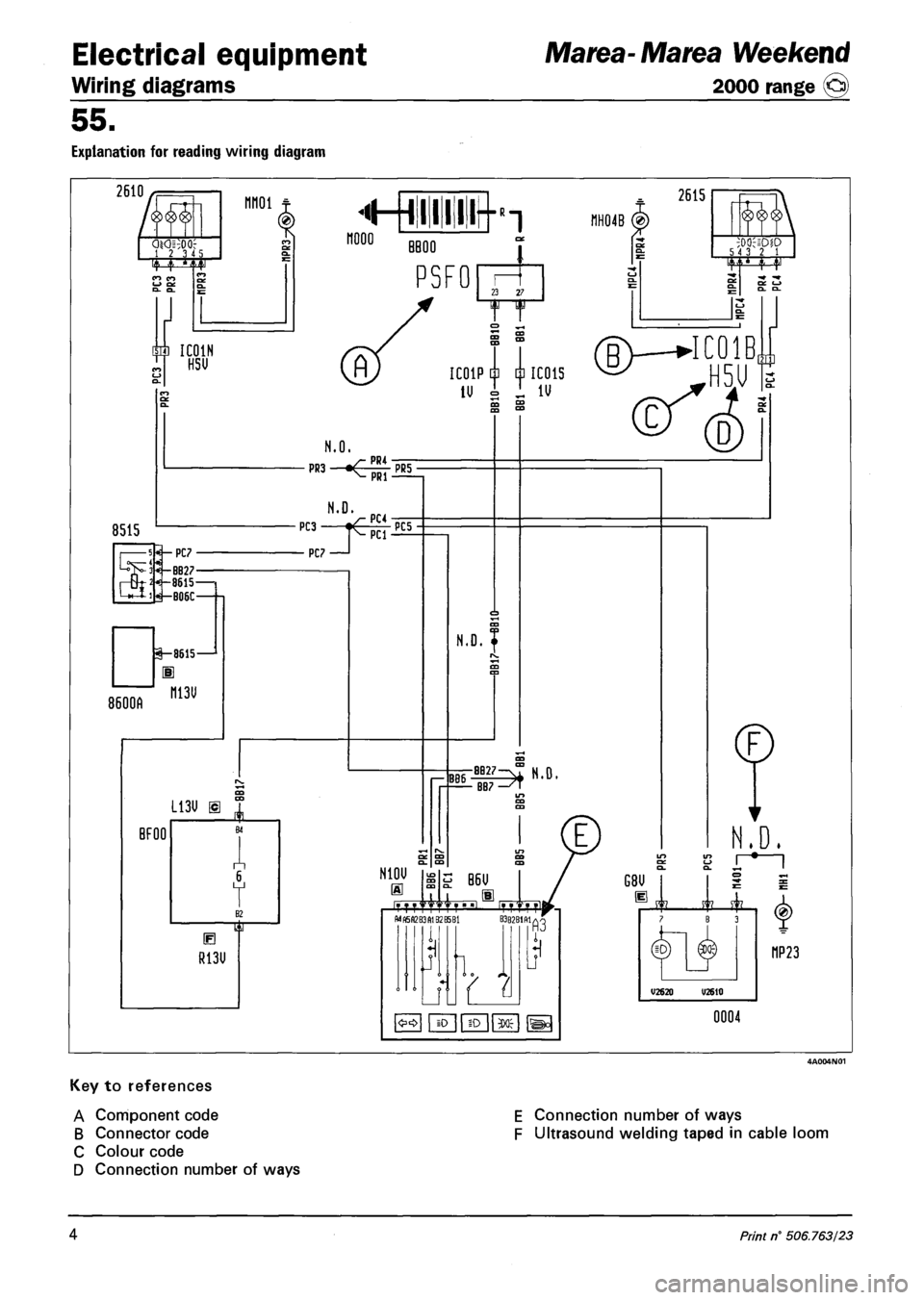
EXPLANATION FOR READING WIRING DIAGRAM
2610/f=T
1 2 3 "
nnoi t
m IC01H ^ HSU
8515
^— PC7
-BB27 -8615 1 W-B06C-
8600A
1-8615—1
H
ni3u
L13U m
BFOO
V
B
R13U
FT
2615
BBOO
PSFO 23 27
5 4 3 2 1 TO
A
m m
II IC01P m m IC01S
lUsi.1V
(BWIC01B,
N.O.
p"3
• PC? •
PC3 T^lFTi£5 PCI •
N10U
« ii
EN
N.D. |
D
— BB7 —'T
MN5A2B3A132B5B1
i
B6U
4, , 11 TT^l ITT B3B2B1M/V
N.D.
LO to 1
G8U
11
<£0 iO ID
£2 £1 B 3
V2620 U2610
(0)
MP23
0004
Key to references
A Component code
B Connector code
C Colour code
D Connection number of ways
E Connection number of ways
F Ultrasound welding taped in cable loom
4 Print n° 506.763/23
Page 228 of 330
Electrical equipment
Component location
Marea-Marea Weekend
2000 range @)
55.
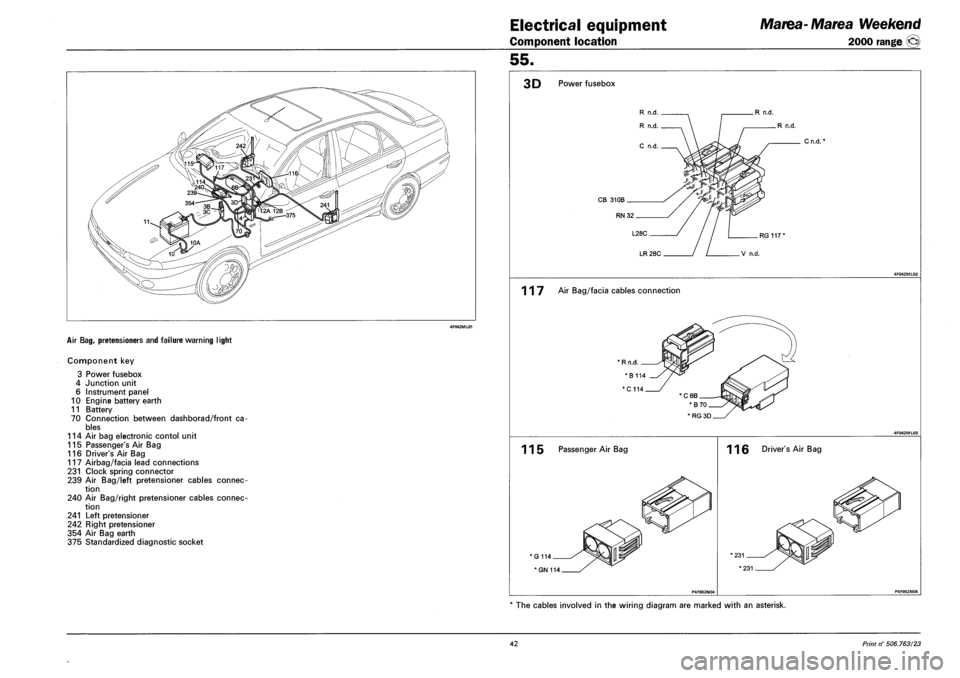
AIR BAG, PRETENSIONERS AND FAILURE WARNING LIGHT
Component key
3 Power fusebox
4 Junction unit
6 Instrument panel
10 Engine battery earth
11 Battery
70 Connection between dashborad/front ca
bles
114 Air bag electronic contol unit
115 Passenger's Air Bag
116 Driver's Air Bag
117 Airbag/facia lead connections
231 Clock spring connector
239 Air Bag/left pretensioner cables connec
tion
240 Air Bag/right pretensioner cables connec
tion
241 Left pretensioner
242 Right pretensioner
354 Air Bag earth
375 Standardized diagnostic socket
3D Power fusebox
R n.d.
R n.d.
CB 310B
RN32
Cn.d.
LR 28C
117 Air Bag/facia cables connection
115 Passenger Air Bag
G114
* GN 114
116 Driver's Air Bag
The cables involved in the wiring diagram are marked with an asterisk.
42 Print n° 506.763/23