connector I FIAT MAREA 2001 1.G User Guide
[x] Cancel search | Manufacturer: FIAT, Model Year: 2001, Model line: MAREA, Model: FIAT MAREA 2001 1.GPages: 330
Page 101 of 330
Marea- Marea Weekend 9™
2000 range (§)
4F015XJ03
Engine
Fuel feed system
ijo.
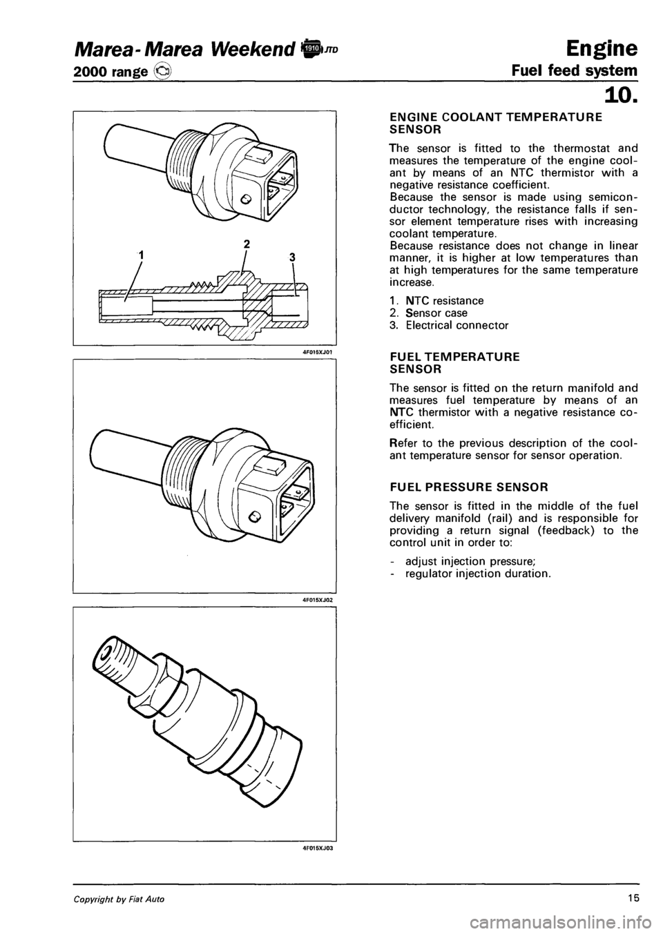
ENGINE COOLANT TEMPERATURE
SENSOR
The sensor is fitted to the thermostat and
measures the temperature of the engine cool
ant by means of an NTC thermistor with a
negative resistance coefficient.
Because the sensor is made using semicon
ductor technology, the resistance falls if sen
sor element temperature rises with increasing
coolant temperature.
Because resistance does not change in linear
manner, it is higher at low temperatures than
at high temperatures for the same temperature
increase.
1. NTC resistance
2. Sensor case
3. Electrical connector
FUEL TEMPERATURE
SENSOR
The sensor is fitted on the return manifold and
measures fuel temperature by means of an
NTC thermistor with a negative resistance co
efficient.
Refer to the previous description of the cool
ant temperature sensor for sensor operation.
FUEL PRESSURE SENSOR
The sensor is fitted in the middle of the fuel
delivery manifold (rail) and is responsible for
providing a return signal (feedback) to the
control unit in order to:
- adjust injection pressure;
- regulator injection duration.
Copyright by Fiat Auto 15
Page 102 of 330
![FIAT MAREA 2001 1.G User Guide Engine
Fuel feed system
JTD Marea-Marea Weekend ©
2000 range ©
10.
iH
ft
B I 0 ] I D
[ 0 0 1 1
D
0 1 <fi=2 1 1 15J
GLOW PLUG PREHEATING CONTROL
UNIT
The glow plugs are controlled by mea FIAT MAREA 2001 1.G User Guide Engine
Fuel feed system
JTD Marea-Marea Weekend ©
2000 range ©
10.
iH
ft
B I 0 ] I D
[ 0 0 1 1
D
0 1 <fi=2 1 1 15J
GLOW PLUG PREHEATING CONTROL
UNIT
The glow plugs are controlled by mea](/img/10/4653/w960_4653-101.png)
Engine
Fuel feed system
JTD Marea-Marea Weekend ©
2000 range ©
10.
iH
ft
B I 0 ] I D
[ 0 0 1 1
D
0 1
UNIT
The glow plugs are controlled by means of a
preheating control unit under the direct con
trol of the injection control unit.
The preheating control unit contains a smart
relay that sends a return response (feedback)
to the injection control unit, which is thus in
formed of faults in the preheating control unit
or glow plug short-circuits to earth.
The figure shows the connectors on the base
of the preheating control unit and the pin-out
1. Earth
2. Injection control unit (pin 22)
3. Power supply from main injection relay
4. Not connected
5. Injection control unit (pin 62)
8. Positive from battery (+30)
G. Glow plugs (only four outputs are used)
ACCELERATOR
PEDAL POTENTIOMETER
Accelerator pedal position is converted to an
electrical voltage signal and send to the injec
tion control unit by a potentiometer connected
to the accelerator pedal.
Accelerator pedal position is processed to
gether with rpm information to provide injec
tion times and pressure.
The sensor consists of a case (1) secured to
the pedal by a flange, which contains an axi-
ally-positioned shaft (2) connected to two
potentiometers (3): main and safety potenti
ometers.
A coil spring on the shaft ensures the correct
resistance to pressure while a second spring
ensures return upon release.
16 Publication no. 506.763/24
Page 103 of 330
Marea-Marea Weekend 9 -™ Engine
2000 range (j§) Fuel feed system
10.
I I TEST
4F017XJ01
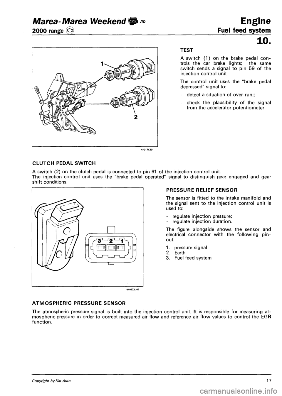
A switch (1) on the brake pedal con
trols the car brake lights; the same
switch sends a signal to pin 59 of the
injection control unit
The control unit uses the "brake pedal
depressed" signal to:
- detect a situation of over-run;;
- check the plausibility of the signal
from the accelerator potentiometer
CLUTCH PEDAL SWITCH
A switch (2) on the clutch pedal is connected to pin 61 of the injection control unit.
The injection control unit uses the "brake pedal operated" signal to distinguish gear engaged and gear
shift conditions.
PRESSURE RELIEF SENSOR
The sensor is fitted to the intake manifold and
the signal sent to the injection control unit is
used to:
- regulate injection pressure;
- regulate injection duration.
The figure alongside shows the sensor and
electrical connector with the following pin-
out:
1. pressure signal
2. Earth
3. Fuel feed system
ATMOSPHERIC PRESSURE SENSOR
The atmospheric pressure signal is built into the injection control unit. It is responsible for measuring at
mospheric pressure in order to correct measured air flow and reference air flow values to control the EGR
function.
Copyright by Fiat Auto 17
Page 116 of 330
Engine
Fuel feed system
Marea-Marea Weekend
2000 range ©
THROTTLE CASING
Removing-refitting
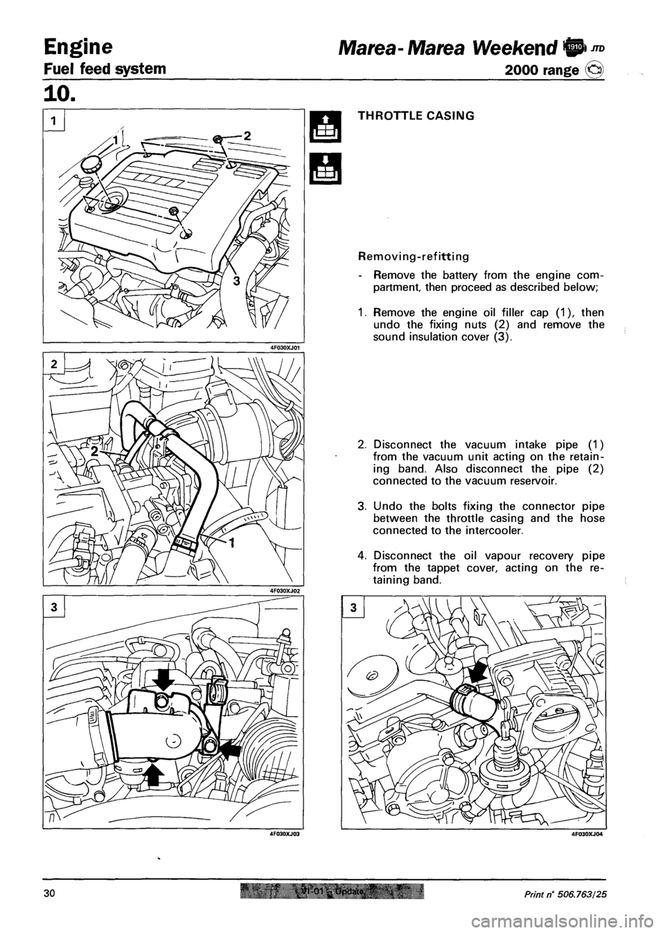
- Remove the battery from the engine com
partment, then proceed as described below;
1. Remove the engine oil filler cap (1), then
undo the fixing nuts (2) and remove the
sound insulation cover (3).
2. Disconnect the vacuum intake pipe (1)
from the vacuum unit acting on the retain
ing band. Also disconnect the pipe (2)
connected to the vacuum reservoir.
3. Undo the bolts fixing the connector pipe
between the throttle casing and the hose
connected to the intercooler.
4. Disconnect the oil vapour recovery pipe
from the tappet cover, acting on the re
taining band.
30 Print n° 506.763/25
Page 120 of 330
Engine
Fuel feed system
Marea- Marea Weekend 9 ™
2000 range ©
SOLENOID VALVE ON VACUUM RES
ERVOIR FOR THROTTLE CASING
PNEUMATIC VALVE
Removing-refitting
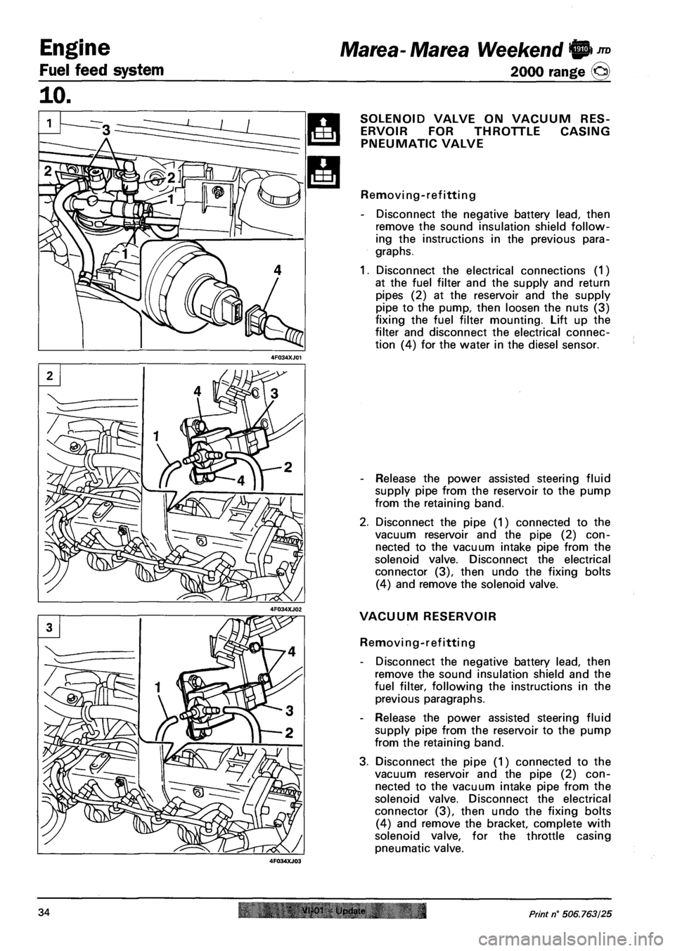
- Disconnect the negative battery lead, then
remove the sound insulation shield follow
ing the instructions in the previous para
graphs.
1. Disconnect the electrical connections (1)
at the fuel filter and the supply and return
pipes (2) at the reservoir and the supply
pipe to the pump, then loosen the nuts (3)
fixing the fuel filter mounting. Lift up the
filter and disconnect the electrical connec
tion (4) for the water in the diesel sensor.
- Release the power assisted steering fluid
supply pipe from the reservoir to the pump
from the retaining band.
2. Disconnect the pipe (1) connected to the
vacuum reservoir and the pipe (2) con
nected to the vacuum intake pipe from the
solenoid valve. Disconnect the electrical
connector (3), then undo the fixing bolts
(4) and remove the solenoid valve.
VACUUM RESERVOIR
Removing-refitting
- Disconnect the negative battery lead, then
remove the sound insulation shield and the
fuel filter, following the instructions in the
previous paragraphs.
- Release the power assisted steering fluid
supply pipe from the reservoir to the pump
from the retaining band.
3. Disconnect the pipe (1) connected to the
vacuum reservoir and the pipe (2) con
nected to the vacuum intake pipe from the
solenoid valve. Disconnect the electrical
connector (3), then undo the fixing bolts
(4) and remove the bracket, complete with
solenoid valve, for the throttle casing
pneumatic valve.
34 VI-01 Update IN Print n° 506.763/25
Page 121 of 330
Ma tea- Marea Weekend 9 m
2000 range ©)
Engine
Fuel feed system
10.
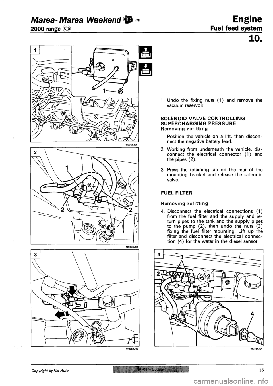
1. Undo the fixing nuts (1) and remove the
vacuum reservoir.
SOLENOID VALVE CONTROLLING
SUPERCHARGING PRESSURE
Removing-refitting
- Position the vehicle on a lift, then discon
nect the negative battery lead.
2. Working from underneath the vehicle, dis
connect the electrical connector (1) and
the pipes (2).
3. Press the retaining tab on the rear of the
mounting bracket and release the solenoid
valve.
FUEL FILTER
Removing-refitting
4. Disconnect the electrical connections (1)
from the fuel filter and the supply and re
turn pipes to the tank and the supply pipes
to the pump (2), then undo the nuts (3)
fixing the fuel filter mounting. Lift up the
filter and disconnect the electrical connec
tion (4) for the water in the diesel sensor.
Copyright by Fiat Auto oi upjdin 35
Page 122 of 330
Engine
Fuel feed system
Marea- Marea Weekend @ ™
2000 range ©
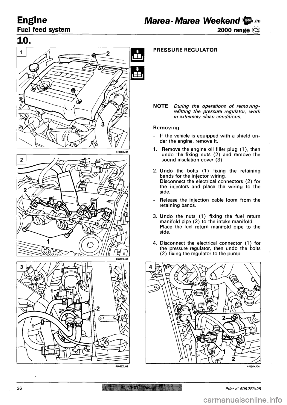
PRESSURE REGULATOR
NOTE During the operations of removing-
refitting the pressure regulator, work
in extremely clean conditions.
Removing
- If the vehicle is equipped with a shield un
der the engine, remove it.
1. Remove the engine oil filler plug (1), then
undo the fixing nuts (2) and remove the
sound insulation cover (3).
2. Undo the bolts (1) fixing the retaining
bands for the injector wiring.
Disconnect the electrical connectors (2) for
the injectors and place the wiring to the
side.
- Release the injection cable loom from the
retaining bands.
3. Undo the nuts (1) fixing the fuel return
manifold pipe (2) to the intake manifold.
Place the fuel return manifold pipe to the
side.
4. Disconnect the electrical connector (1) for
the pressure regulator, then undo the bolts
(2) fixing the regulator to the pump.
36 Print n° 506.763/25
Page 123 of 330
Marea-Marea Weekend H nD Engine
2000 range (Q) Fuel feed system
10.
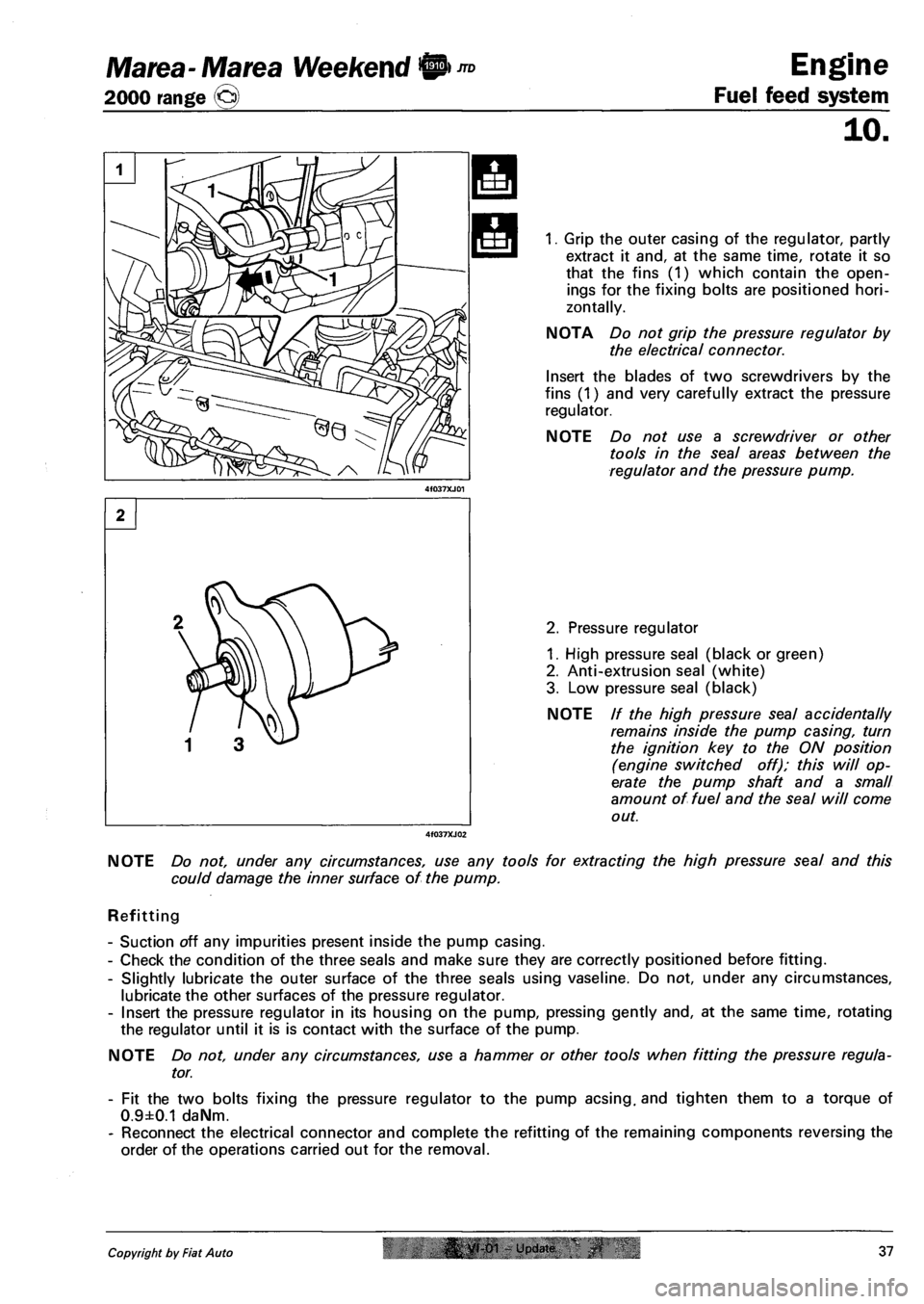
1. Grip the outer casing of the regulator, partly
extract it and, at the same time, rotate it so
that the fins (1) which contain the open
ings for the fixing bolts are positioned hori
zontally.
NOTA Do not grip the pressure regulator by
the electrical connector.
Insert the blades of two screwdrivers by the
fins (1) and very carefully extract the pressure
regulator.
NOTE Do not use a screwdriver or other
tools in the seal areas between the
regulator and the pressure pump.
2. Pressure regulator
1. High pressure seal (black or green)
2. Anti-extrusion seal (white)
3. Low pressure seal (black)
NOTE // the high pressure seal accidentally
remains inside the pump casing, turn
the ignition key to the ON position
(engine switched off); this will op
erate the pump shaft and a small
amount of fuel and the seal will come
out.
NOTE Do not, under any circumstances, use any tools for extracting the high pressure seal and this
could damage the inner surface of the pump.
Refitting
- Suction off any impurities present inside the pump casing.
- Check the condition of the three seals and make sure they are correctly positioned before fitting.
- Slightly lubricate the outer surface of the three seals using vaseline. Do not, under any circumstances,
lubricate the other surfaces of the pressure regulator.
- Insert the pressure regulator in its housing on the pump, pressing gently and, at the same time, rotating
the regulator until it is is contact with the surface of the pump.
NOTE Do not, under any circumstances, use a hammer or other tools when fitting the pressure regula
tor.
- Fit the two bolts fixing the pressure regulator to the pump acsing. and tighten them to a torque of
0.9±0.1 daNm.
- Reconnect the electrical connector and complete the refitting of the remaining components reversing the
order of the operations carried out for the removal.
Copyright by Fiat Auto |& yt-01 - Update 37
Page 134 of 330
Electrical equipment
Junction unit
Marea-Marea Weekend
2000 range ©
55.
Junction unit
»F11=
~T~ II l;
•F9° |["^FT^1| °F10°ir°F13=
| ^14=- ir=F15«=- II
»F12=
SLHHItHia r i i i •
3F4= ir^F8=1l =F7="|| °F6 = 1
I I I I I 1 I '
14 5 4 12-
lor
1-11-J
I 1
J 7_
a o_o o_o OLD n.
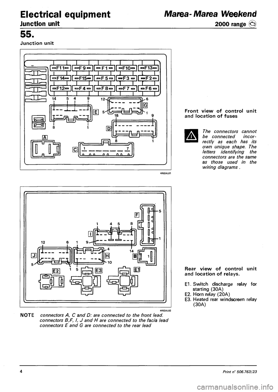
Front view of control unit
and location of fuses
The connectors cannot
be connected incor
rectly as each has its
own unique shape. The
letters identifying the
connectors are the same
as those used in the
wiring diagrams .
NOTE connectors A, C and D: are connected to the front lead.
connectors B,F, I, J and H are connected to the facia lead
connectors E and G are connected to the rear lead
Rear view of control unit
and location of relays.
E1. Switch discharge relay for
starting (30A)
E2. Horn relay (20A)
E3. Heated rear windscreen relay
(30A)
4 Print n° 506.763/23
Page 135 of 330
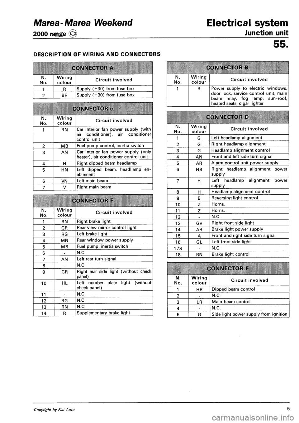
Marea-Marea Weekend
2000 range Q
DESCRIPTION OF WIRING AND CONNECTORS
CONNECTOR A
N.
No.
Wiring
colour Circuit involved
1 R Supply (+30) from fuse box
2 BR Supply (+30) from fuse box
CONNECTOR c
N. No.
Wiring colour Circuit involved
1 RN Car interior fan power supply (with
air conditioner), air conditioner
control unit
2 MB Fuel pump control, inertia switch
3 AN Car interior fan power supply (only heater), air conditioner control unit
4 H Right dipped beam headlamp
5 HN Left dipped beam, headllamp en
ablement
6 VN Left main beam
7 V Right main beam
CONNECTOR E
N.
No.
Wiring colour Circuit involved
1 RN Right brake light
2 GR Rear view mirror control light
3 RG Left brake light
4 MN Rear window power supply
5 MB Fuel pump, inertia switch
6 -N.C.
7 AN Left rear turn signal
8 -N.C.
9 GR Right rear side light (without check
panel)
10 HL Left number plate light (without
check panel)
11 -N.C.
12 RG N.C.
13 RN N.C.
14 R Supplementary brake light
Electrical system
Junction unit
55.
CONNECTOR B
N. No.
Wiring
colour Circuit involved
1 R Power supply to electric windows, door lock, service control unit, main beam relay, fog lamp, sun-roof, heated seats, cigar lighter
CONNECTOR D
N.
No.
Wiring colour Circuit involved
1 G Left headlamp alignment
2 G Right headlamp alignment
3 G Headlamp alignment control
4 AN Front and left side turn signal
5 AR Alarm control unit power supply
6 HB Right headlamp alignment power
supply
7 H Left headlamp alignment power
supply
8 H Headlamp alignment control
9 B Reversing light control
10 Z Horns.
11 Z Horns.
12 -N.C.
13 GV Right front side light
14 AR Brake light power supply
15 A Front and right side turn signal
16 GL Left front side light
17S -N.C.
18 RN Brake light control
CONNECTOR F
N.
No.
Wiring colour Circuit involved
1 HR Dipped beam control
2 -N.C.
3 LR Main beam control
4 -N.C.
5 G Side light power supply from ignition
Copyright by Fiat Auto 5