Fuel injection FIAT MAREA 2001 1.G Owner's Guide
[x] Cancel search | Manufacturer: FIAT, Model Year: 2001, Model line: MAREA, Model: FIAT MAREA 2001 1.GPages: 330
Page 106 of 330
Engine
Fuel feed system
JTD Marea-Marea Weekend @
2000 range ©
10.
7^ £3
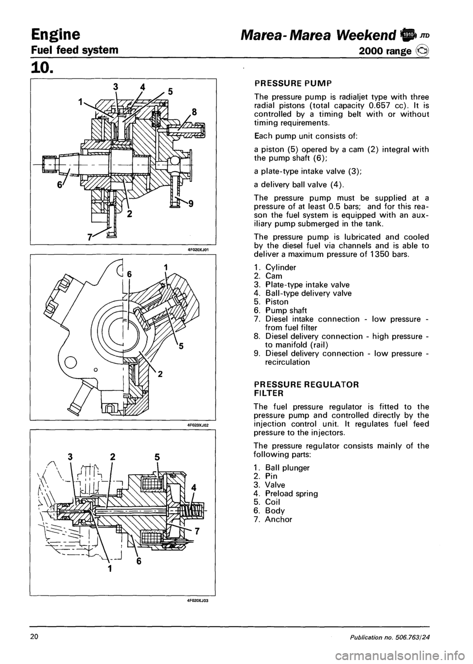
PRESSURE PUMP
The pressure pump is radialjet type with three
radial pistons (total capacity 0.657 cc). It is
controlled by a timing belt with or without
timing requirements.
Each pump unit consists of:
a piston (5) opered by a cam (2) integral with
the pump shaft (6);
a plate-type intake valve (3);
a delivery ball valve (4).
The pressure pump must be supplied at a
pressure of at least 0.5 bars; and for this rea
son the fuel system is equipped with an aux
iliary pump submerged in the tank.
The pressure pump is lubricated and cooled
by the diesel fuel via channels and is able to
deliver a maximum pressure of 1350 bars.
1.
2.
3.
4.
5.
6.
7.
8.
Cylinder
Cam
Plate-type intake valve
Ball-type delivery valve
Piston
Pump shaft
Diesel intake connection -
from fuel filter
Diesel delivery connection
to manifold (rail)
Diesel delivery connection
recirculation
low pressure
high pressure
low pressure
PRESSURE REGULATOR
FILTER
The fuel pressure regulator is fitted to the
pressure pump and controlled directly by the
injection control unit. It regulates fuel feed
pressure to the injectors.
The pressure regulator consists mainly of the
following parts:
1. Ball plunger
2. Pin
3. Valve
4. Preload spring
5. Coil
6. Body
7. Anchor
20 Publication no. 506.763/24
Page 108 of 330
Engine
Fuel feed system
Marea- Marea Weekend W)JTD
2000 range ©
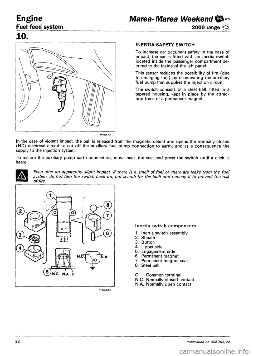
INERTIA SAFETY SWITCH
To increase car occupant safety in the case of
impact, the car is fitted with an inertia switch
located inside the passenger compartment se
cured to the inside of the left panel.
This sensor reduces the possibility of fire (due
to emerging fuel) by deactivating the auxiliary
fuel pump that supplies the injection circuit.
The switch consists of a steel ball, fitted in a
tapered housing, kept in place by the attrac
tion force of a permanent magnet.
In the case of violent impact, the ball is released from the magnetic detent and opens the normally closed
(NC) electrical circuit to cut off the auxiliary fuel pump connection to earth, and as a consequence the
supply to the injection system.
To restore the auxiliary pump earth connection, move back the seat and press the switch until a click is
heard.
Even after an apparently slight impact, if there is a smell of fuel or there are leaks from the fuel
system, do not turn the switch back on, but search for the fault and remedy it to prevent the risk
of fire.
'N.C. N.A. C
Inertia switch components
1. Inertia switch assembly
2. Sheath
3. Button
4. Upper side
5. Engagement side
6. Permanent magnet
7. Permanent magnet seat
8. Steel ball
C Common terminal
N.C. Normally closed contact
N.A. Normally open contact
22 Publication no. 506.763/24
Page 112 of 330
Engine
Fuel feed system
JTD Marea- Marea Weekend 9
2000 range @
10.
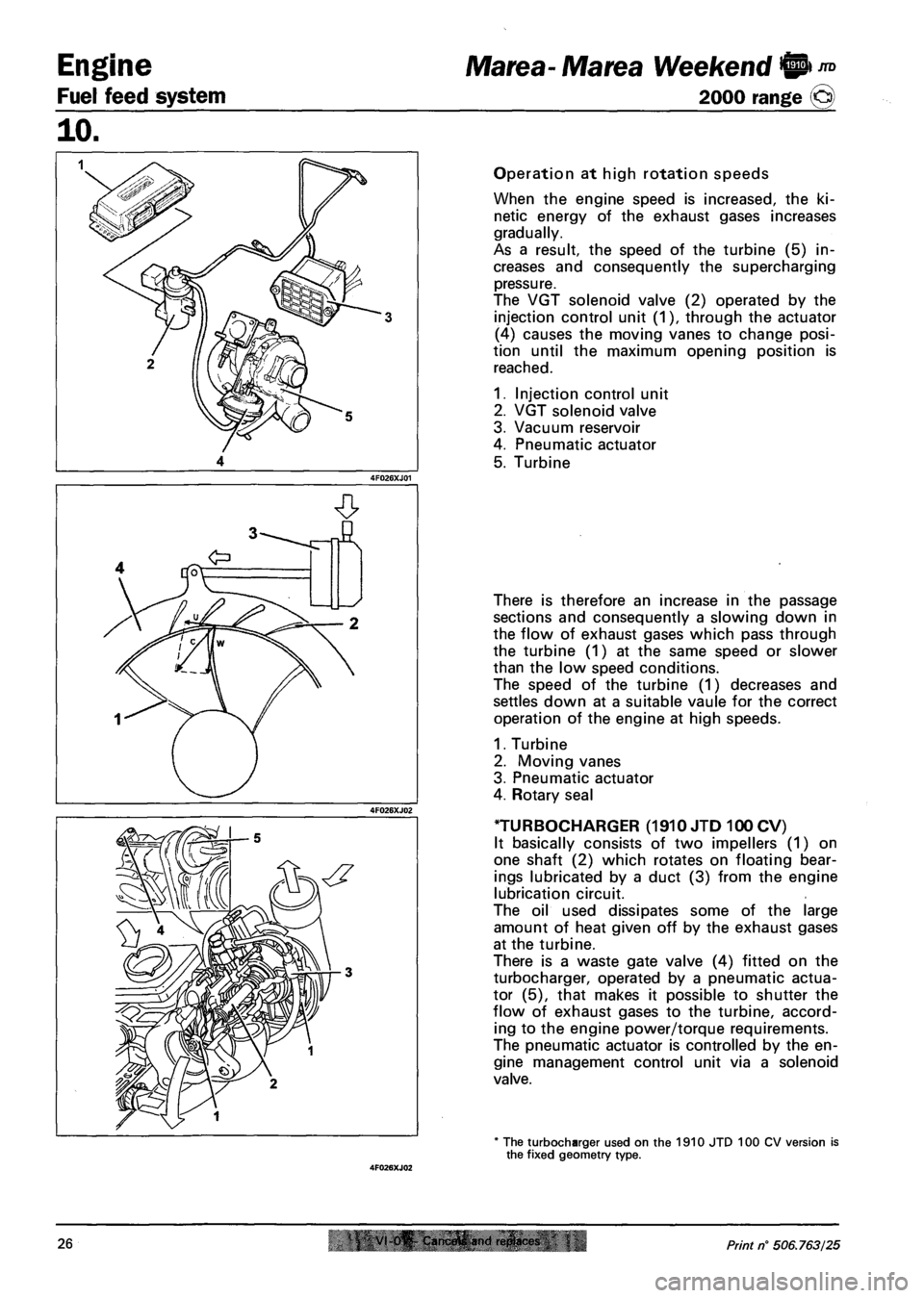
Operation at high rotation speeds
When the engine speed is increased, the ki
netic energy of the exhaust gases increases
gradually.
As a result, the speed of the turbine (5) in
creases and consequently the supercharging
pressure.
The VGT solenoid valve (2) operated by the
injection control unit (1), through the actuator
(4) causes the moving vanes to change posi
tion until the maximum opening position is
reached.
1. Injection control unit
2. VGT solenoid valve
3. Vacuum reservoir
4. Pneumatic actuator
5. Turbine
There is therefore an increase in the passage
sections and consequently a slowing down in
the flow of exhaust gases which pass through
the turbine (1) at the same speed or slower
than the low speed conditions.
The speed of the turbine (1) decreases and
settles down at a suitable vaule for the correct
operation of the engine at high speeds.
1. Turbine
2. Moving vanes
3. Pneumatic actuator
4. Rotary seal
TURBOCHARGER (1910 JTD 100 CV)
It basically consists of two impellers (1) on
one shaft (2) which rotates on floating bear
ings lubricated by a duct (3) from the engine
lubrication circuit.
The oil used dissipates some of the large
amount of heat given off by the exhaust gases
at the turbine.
There is a waste gate valve (4) fitted on the
turbocharger, operated by a pneumatic actua
tor (5), that makes it possible to shutter the
flow of exhaust gases to the turbine, accord
ing to the engine power/torque requirements.
The pneumatic actuator is controlled by the en
gine management control unit via a solenoid
valve.
* The turbocharger used on the 1910 JTD 100 CV version is the fixed geometry type.
26 VI 0^ Cam.frtfi and ri!plact<& Print n° 506.763/25
Page 122 of 330
Engine
Fuel feed system
Marea- Marea Weekend @ ™
2000 range ©
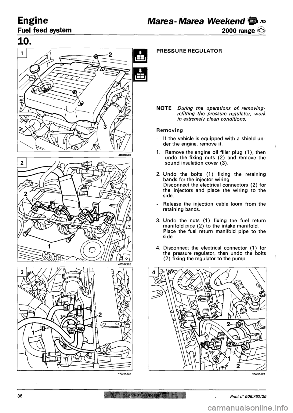
PRESSURE REGULATOR
NOTE During the operations of removing-
refitting the pressure regulator, work
in extremely clean conditions.
Removing
- If the vehicle is equipped with a shield un
der the engine, remove it.
1. Remove the engine oil filler plug (1), then
undo the fixing nuts (2) and remove the
sound insulation cover (3).
2. Undo the bolts (1) fixing the retaining
bands for the injector wiring.
Disconnect the electrical connectors (2) for
the injectors and place the wiring to the
side.
- Release the injection cable loom from the
retaining bands.
3. Undo the nuts (1) fixing the fuel return
manifold pipe (2) to the intake manifold.
Place the fuel return manifold pipe to the
side.
4. Disconnect the electrical connector (1) for
the pressure regulator, then undo the bolts
(2) fixing the regulator to the pump.
36 Print n° 506.763/25
Page 139 of 330
Marea-Marea Weekend Electrical equipment
2000 range (§) Location of components on the car
55.
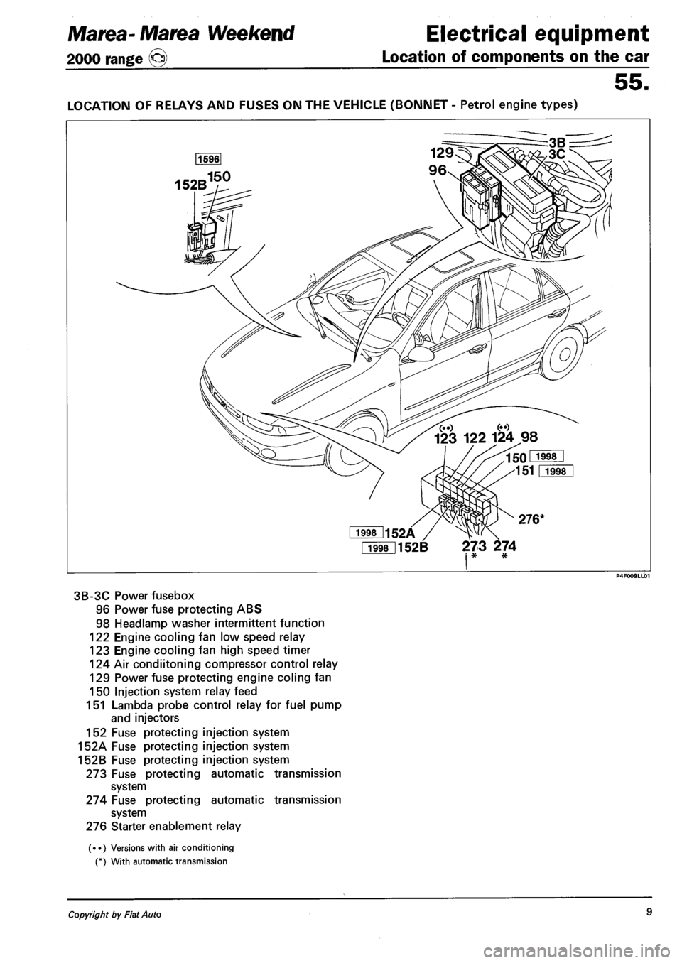
LOCATION OF RELAYS AND FUSES ON THE VEHICLE (BONNET - Petrol engine types)
Fi998l152B 273 274 i * *
3B-3C Power fusebox
96 Power fuse protecting ABS
98 Headlamp washer intermittent function
122 Engine cooling fan low speed relay
123 Engine cooling fan high speed timer
124 Air condiitoning compressor control relay
129 Power fuse protecting engine coling fan
150 Injection system relay feed
151 Lambda probe control relay for fuel pump
and injectors
152 Fuse protecting injection system
152A Fuse protecting injection system
152B Fuse protecting injection system
273 Fuse protecting automatic transmission
system
274 Fuse protecting automatic transmission
system
276 Starter enablement relay
(••) Versions with air conditioning
(*) With automatic transmission
Copyright by Fiat Auto 9
Page 141 of 330
Marea-Marea Weekend Electrical equipment
2000 range (§) Location of components on the car
55.
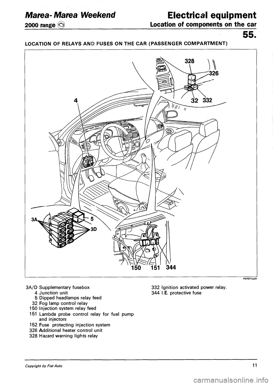
LOCATION OF RELAYS AND FUSES ON THE CAR (PASSENGER COMPARTMENT)
3A/D Supplementary fusebox 332 Ignition activated power relay.
4 Junction unit 344 I.E. protective fuse
5 Dipped headlamps relay feed
32 Fog lamp control relay
150 Injection system relay feed
151 Lambda probe control relay for fuel pump
and injectors
152 Fuse protecting injection system
326 Additional heater control unit
328 Hazard warning lights relay
Copyright by Fiat Auto 11
Page 144 of 330
Electrical equipment
Instrument panel
Marea-Marea Weekend
2000 range ©
55.
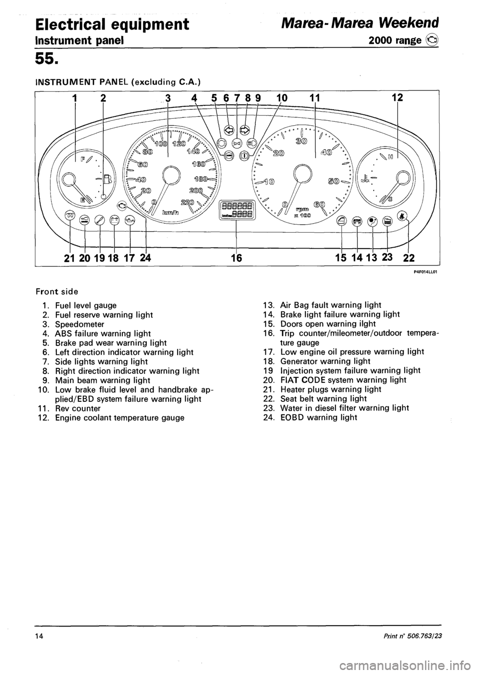
INSTRUMENT PANEL (excluding C.A.)
3 4 56789 10 11 12
21 20 1918 17 24 16 15 14 13 23 22
Front side
1. Fuel level gauge
2. Fuel reserve warning light
3. Speedometer
4. ABS failure warning light
5. Brake pad wear warning light
6. Left direction indicator warning light
7. Side lights warning light
8. Right direction indicator warning light
9. Main beam warning light
10. Low brake fluid level and handbrake ap-
plied/EBD system failure warning light
11. Rev counter
12. Engine coolant temperature gauge
13. Air Bag fault warning light
14. Brake light failure warning light
15. Doors open warning ilght
16. Trip counter/mileometer/outdoor tempera
ture gauge
17. Low engine oil pressure warning light
18. Generator warning light
19 Injection system failure warning light
20. FIAT CODE system warning light
21. Heater plugs warning light
22. Seat belt warning light
23. Water in diesel filter warning light
24. EOBD warning light
14 Print rf 506.763/23
Page 145 of 330
Marea- Marea Weekend
2000 range ©
Electrical equipment
Control module
55.
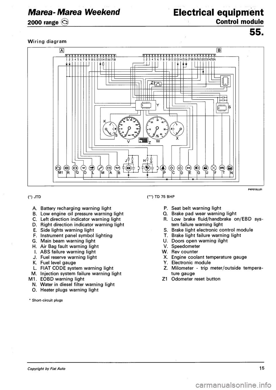
Wiring diagram
.mrmmmL 18 3 4 5 6 7 8 9 10 U 1213 1415161718 |TTTTrTrrrrTTTTT1.TTTTT1pmL 18 3 4 5 6 7 8 9 10 11 121314151617181920213223248586
n ti
O Mill
(*) JTD
A. Battery recharging warning light
B. Low engine oil pressure warning light
C. Left direction indicator warning light
D. Right direction indicator warning light
E. Side lights warning light
F. Instrument panel symbol lighting
G. Main beam warning light
H. Air Bag fault warning light
I. ABS failure warning light
J. Fuel reserve warning light
K. Fuel level gauge
L. FIAT CODE system warning light
M. Injection system failure warning light
M1. EOBD warning light
N. Water in diesel filter warning light
O. Heater plugs warning light
(**) TD 75 BHP
P. Seat belt warning light
Q. Brake pad wear warning light
R. Low brake fluid/handbrake on/EBD sys
tem failure warning light
S. Brake light electronic control module
T. Brake light failure warning light
U. Doors open warning ilght
V. Speedometer
W. Rev counter
X. Engine coolant temperature gauge
Y. Electronic module
Z. Milometer - trip meter/outside tempera
ture gauge
Z1 Odometer reset button
* Short-circuit plugs
Copyright by Fiat Auto 15
Page 146 of 330
Electrical equipment
Instrument panel
Marea- Marea Weekend
2000 range ©
55.
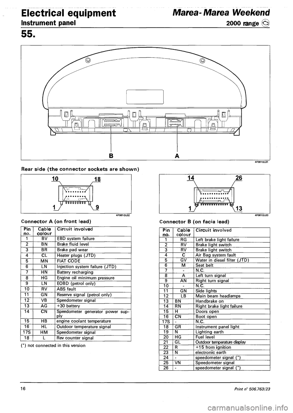
Rear side (the connector sockets are shown)
Connector A (on front lead) Connector B (on facia lead)
Pin no. Cable colour Circuit involved
1 BV EBD system failure
2 BN Brake fluid level
3 BR Brake pad wear
4 CL Heater plugs (JTD)
5 MN FIAT CODE
6 LN Injection system failure (JTD)
7 HN Battery recharging
8 HG Engine oil minimum pressure
9 LN EOBD (petrol only)
10 RV ABS fault
11 GN Reserve signal (petrol only)
12 VB Speedometer signal
13 AG +30 battery
14 CN Speedometer generator power supply
15 HB engine coolant temperature
16 HL Outdoor temperature signal
17S HM Speedometer signal
18 L Rev counter signal
(*) not connected in this version
Pin no. Cable colour Circuit involved
1 RG Left brake light failure
2 RV Brake light switch
3 RV Brake light switch
4 C Air Bag system fault
5 GV Water in diesel filter (JTD)
6 M Seat belt
7 -N.C.
8 A Left turn signal
9 AN Right turn signal
10 -N.C.
11 GN Side lights
12 LB Main beam headlamps
13 BN Handbrake on
14 RN Right brake light failure
15 H Doors open
16 CN Boot open
17S -N.C.
18 GR Instrument panel light
19 N Lighting earth
20 HG Fuel level
21 GL Outdoor temperature display
22 R +15 from ignition
23 N electronic earth
24 -speedometer signal (*)
25 VN Speedometer signal
26 -speedometer signal (*)
16 Print n° 506.763/23
Page 148 of 330
Electrical equipment
Control module
Marea- Marea Weekend
2000 range ©
55.
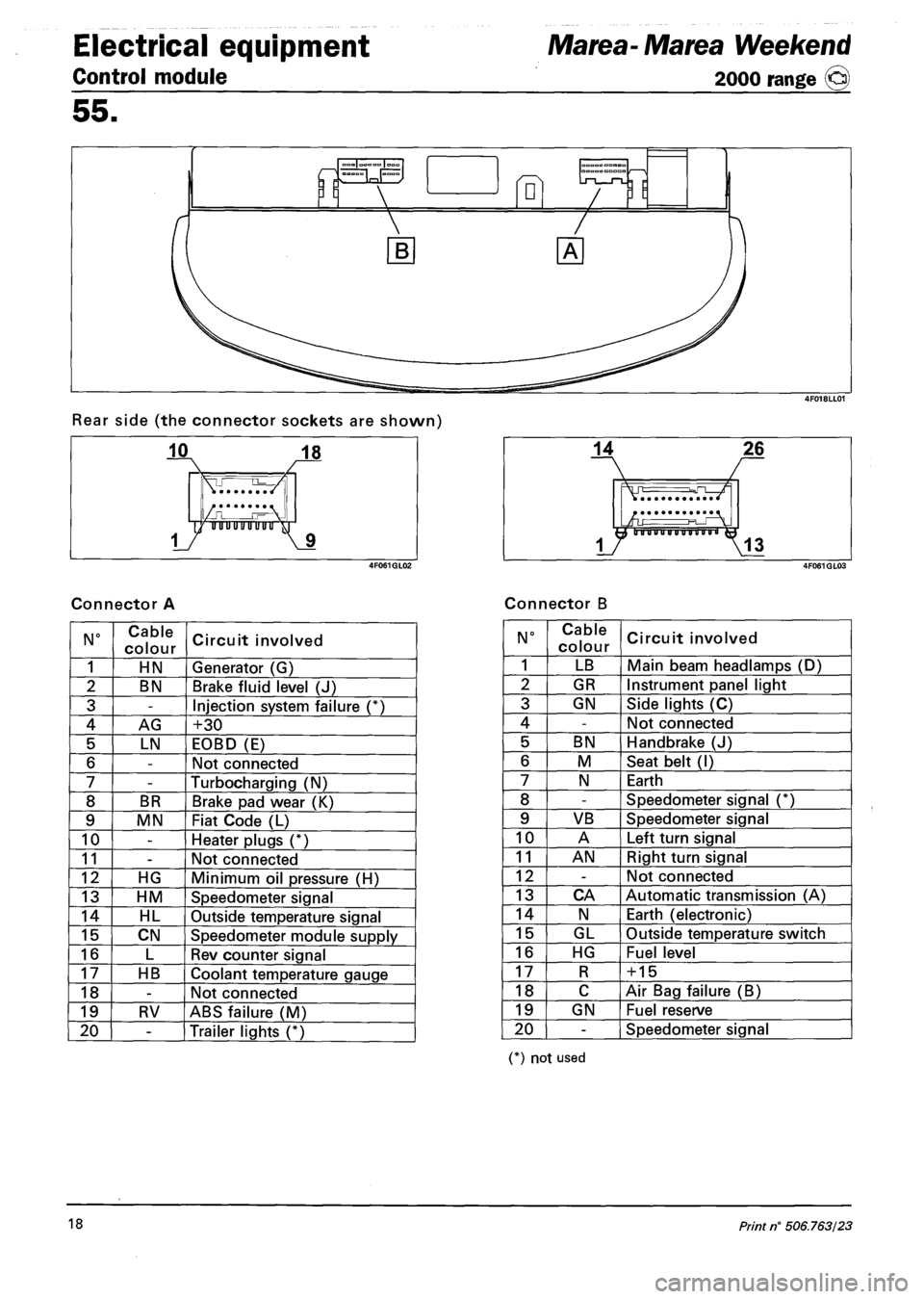
Rear side (the connector sockets are shown)
Connector A Connector B
N° Cable
colour Circuit involved
1 HN Generator (G)
2 BN Brake fluid level (J)
3 -Injection system failure (*)
4 AG +30
5 LN EOBD (E)
6 -Not connected
7 -Turbocharging (N)
8 BR Brake pad wear (K)
9 MN Fiat Code (L)
10 -Heater plugs (*)
11 -Not connected
12 HG Minimum oil pressure (H)
13 HM Speedometer signal
14 HL Outside temperature signal
15 CN Speedometer module supply
16 L Rev counter signal
17 HB Coolant temperature gauge
18 -Not connected
19 RV ABS failure (M)
20 -Trailer lights (*)
N° Cable
colour Circuit involved
1 LB Main beam headlamps (D)
2 GR Instrument panel light
3 GN Side lights (C)
4 -Not connected
5 BN Handbrake (J)
6 M Seat belt (I)
7 N Earth
8 -Speedometer signal (*)
9 VB Speedometer signal
10 A Left turn signal
11 AN Right turn signal
12 -Not connected
13 CA Automatic transmission (A)
14 N Earth (electronic)
15 GL Outside temperature switch
16 HG Fuel level
17 R + 15
18 C Air Bag failure (B)
19 GN Fuel reserve
20 -Speedometer signal
(*) not used
18 Print n° 506.763/23