Seat FIAT MAREA 2001 1.G Workshop Manual
[x] Cancel search | Manufacturer: FIAT, Model Year: 2001, Model line: MAREA, Model: FIAT MAREA 2001 1.GPages: 330
Page 13 of 330
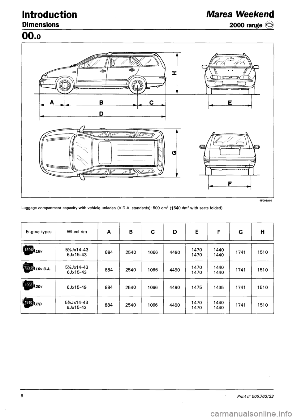
Introduction
Dimensions
Marea Weekend
2000 range @)
OO.o
Luggage compartment capacity with vehicle unladen (V.D.A. standards): 500 dm3 (1540 dm3 with seats folded)
Engine types Wheel rim A B C D E F G H
5Y2Jx14-43
6Jx15-43 884 2540 1066 4490 1470 1470 1440
1440 1741 1510
5%Jx14-43 6Jx15-43 884 2540 1066 4490 1470
1470 1440 1440 1741 1510
ifipl 20 v 6Jx15-49 884 2540 1066 4490 1475 1435 1741 1510
51/2Jx14-43
6Jx15-43 884 2540 1066 4490 1470
1470 1440 1440 1741 1510
6 Print rf 506.763/23
Page 24 of 330
Marea- Marea Weekend
2000 range ©
Technical Data
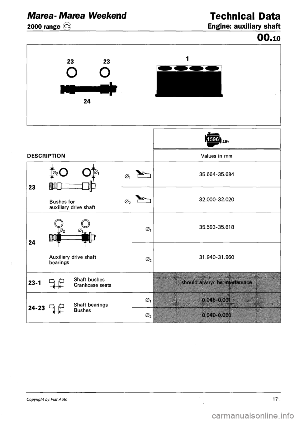
Engine: auxiliary shaft
DESCRIPTION
16v
Values in mm
OO.io
0,
23
NO Q
•0D=Ljtr
Bushes for
auxiliary drive shaft
01
02
35.664-35.684
32.000-32.020
24
|02 eu
my i
Auxiliary drive shaft
bearings
01
02
35.593-35.618
31.940-31.960
1 0\ O Shaft DUSnes 1 -4-K- Crankcase seats
24-23 Shaft bearings
Bushes
0i
0
should always be interfetrnce
0.046-0.091
0 040-0.080
Copyright by Fiat Auto 17
Page 25 of 330
Technical Data Marea-Marea Weekend
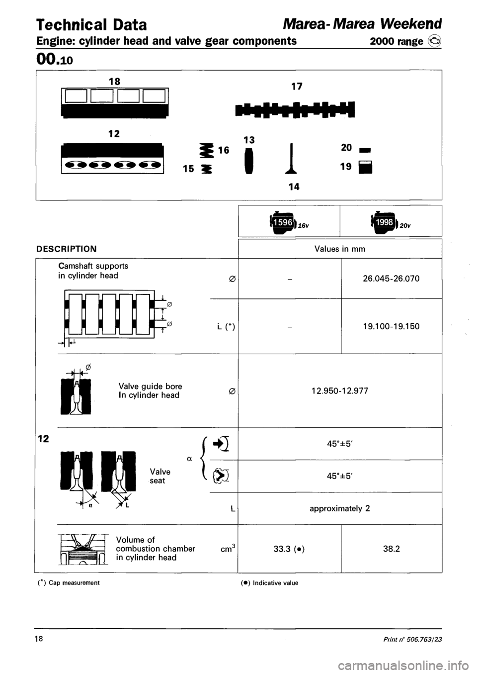
Engine: cylinder head and valve gear components 2000 range (§)
OO.io
DESCRIPTION Values in mm
Camshaft supports
in cylinder head 0
i_n
26.045-26.070
19.100-19.150
n
Valve guide bore
In cylinder head 0 12.950-12.977
12
HQ 45°±5'
a Valve
seat S3 45°±5'
approximately 2
Volume of
combustion chamber
in cylinder head cm" 33.3 (•) 38.2
( ) Cap measurement (•) Indicative value
18 Print n° 506.763/23
Page 30 of 330
Marea- Marea Weekend
2000 range @)
Technical Data
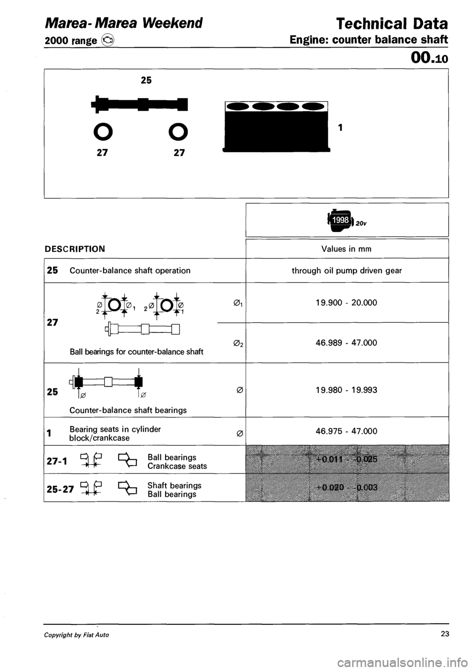
Engine: counter balance shaft
DESCRIPTION
OO.io
20v
Values in mm
25 Counter-balance shaft operation through oil pump driven gear
27
01
0
Ball bearings for counter-balance shaft
02
19.900 - 20.000
46.989 - 47.000
25 c)tr=tt=i
Counter-balance shaft bearings
0 19.980 - 19.993
« Bearing seats in cylinder
block/crankcase 0 46.975 - 47.000
9_ Oi p CV., Ball beari
-4+- V-J Crankcasf ngs
Crankcase seats
25-27 Shaft bearings
Ball bearings
+0.011 - -0.025
• 0.020 -0.003
Copyright by Fiat Auto 23
Page 108 of 330
Engine
Fuel feed system
Marea- Marea Weekend W)JTD
2000 range ©
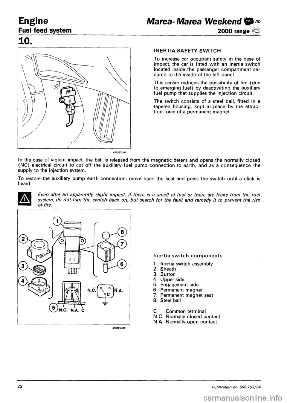
INERTIA SAFETY SWITCH
To increase car occupant safety in the case of
impact, the car is fitted with an inertia switch
located inside the passenger compartment se
cured to the inside of the left panel.
This sensor reduces the possibility of fire (due
to emerging fuel) by deactivating the auxiliary
fuel pump that supplies the injection circuit.
The switch consists of a steel ball, fitted in a
tapered housing, kept in place by the attrac
tion force of a permanent magnet.
In the case of violent impact, the ball is released from the magnetic detent and opens the normally closed
(NC) electrical circuit to cut off the auxiliary fuel pump connection to earth, and as a consequence the
supply to the injection system.
To restore the auxiliary pump earth connection, move back the seat and press the switch until a click is
heard.
Even after an apparently slight impact, if there is a smell of fuel or there are leaks from the fuel
system, do not turn the switch back on, but search for the fault and remedy it to prevent the risk
of fire.
'N.C. N.A. C
Inertia switch components
1. Inertia switch assembly
2. Sheath
3. Button
4. Upper side
5. Engagement side
6. Permanent magnet
7. Permanent magnet seat
8. Steel ball
C Common terminal
N.C. Normally closed contact
N.A. Normally open contact
22 Publication no. 506.763/24
Page 135 of 330
Marea-Marea Weekend
2000 range Q
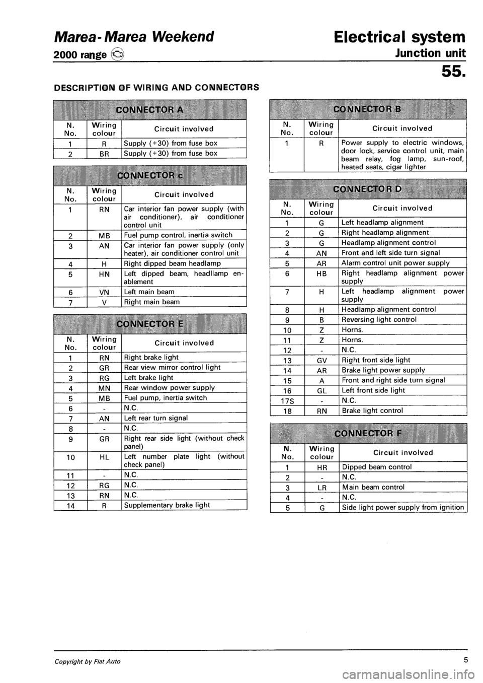
DESCRIPTION OF WIRING AND CONNECTORS
CONNECTOR A
N.
No.
Wiring
colour Circuit involved
1 R Supply (+30) from fuse box
2 BR Supply (+30) from fuse box
CONNECTOR c
N. No.
Wiring colour Circuit involved
1 RN Car interior fan power supply (with
air conditioner), air conditioner
control unit
2 MB Fuel pump control, inertia switch
3 AN Car interior fan power supply (only heater), air conditioner control unit
4 H Right dipped beam headlamp
5 HN Left dipped beam, headllamp en
ablement
6 VN Left main beam
7 V Right main beam
CONNECTOR E
N.
No.
Wiring colour Circuit involved
1 RN Right brake light
2 GR Rear view mirror control light
3 RG Left brake light
4 MN Rear window power supply
5 MB Fuel pump, inertia switch
6 -N.C.
7 AN Left rear turn signal
8 -N.C.
9 GR Right rear side light (without check
panel)
10 HL Left number plate light (without
check panel)
11 -N.C.
12 RG N.C.
13 RN N.C.
14 R Supplementary brake light
Electrical system
Junction unit
55.
CONNECTOR B
N. No.
Wiring
colour Circuit involved
1 R Power supply to electric windows, door lock, service control unit, main beam relay, fog lamp, sun-roof, heated seats, cigar lighter
CONNECTOR D
N.
No.
Wiring colour Circuit involved
1 G Left headlamp alignment
2 G Right headlamp alignment
3 G Headlamp alignment control
4 AN Front and left side turn signal
5 AR Alarm control unit power supply
6 HB Right headlamp alignment power
supply
7 H Left headlamp alignment power
supply
8 H Headlamp alignment control
9 B Reversing light control
10 Z Horns.
11 Z Horns.
12 -N.C.
13 GV Right front side light
14 AR Brake light power supply
15 A Front and right side turn signal
16 GL Left front side light
17S -N.C.
18 RN Brake light control
CONNECTOR F
N.
No.
Wiring colour Circuit involved
1 HR Dipped beam control
2 -N.C.
3 LR Main beam control
4 -N.C.
5 G Side light power supply from ignition
Copyright by Fiat Auto 5
Page 138 of 330
Electrical system
Protection and security devices
Marea-Marea Weekend
2000 range Q
55.
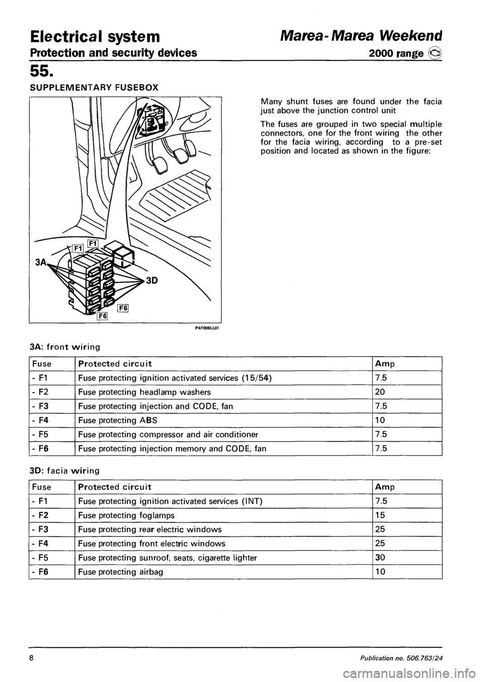
SUPPLEMENTARY FUSEBOX
Many shunt fuses are found under the facia
just above the junction control unit
The fuses are grouped in two special multiple
connectors, one for the front wiring the other
for the facia wiring, according to a pre-set
position and located as shown in the figure:
3A: front wiring
Fuse Protected circuit Amp
- F1 Fuse protecting ignition activated services (15/54) 7.5
- F2 Fuse protecting headlamp washers 20
- F3 Fuse protecting injection and CODE, fan 7.5
- F4 Fuse protecting ABS 10
- F5 Fuse protecting compressor and air conditioner 7.5
- F6 Fuse protecting injection memory and CODE, fan 7.5
3D: facia wiring
Fuse Protected circuit Amp
- F1 Fuse protecting ignition activated services (INT) 7.5
- F2 Fuse protecting foglamps 15
- F3 Fuse protecting rear electric windows 25
- F4 Fuse protecting front electric windows 25
- F5 Fuse protecting sunroof, seats, cigarette lighter 30
- F6 Fuse protecting airbag 10
8 Publication no. 506.763/24
Page 144 of 330
Electrical equipment
Instrument panel
Marea-Marea Weekend
2000 range ©
55.
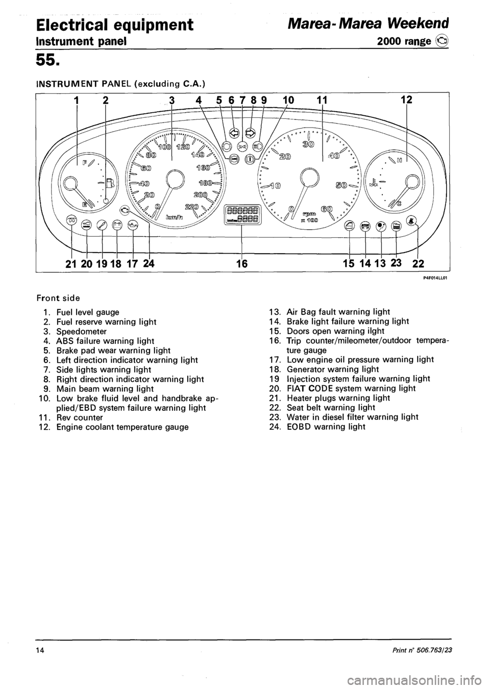
INSTRUMENT PANEL (excluding C.A.)
3 4 56789 10 11 12
21 20 1918 17 24 16 15 14 13 23 22
Front side
1. Fuel level gauge
2. Fuel reserve warning light
3. Speedometer
4. ABS failure warning light
5. Brake pad wear warning light
6. Left direction indicator warning light
7. Side lights warning light
8. Right direction indicator warning light
9. Main beam warning light
10. Low brake fluid level and handbrake ap-
plied/EBD system failure warning light
11. Rev counter
12. Engine coolant temperature gauge
13. Air Bag fault warning light
14. Brake light failure warning light
15. Doors open warning ilght
16. Trip counter/mileometer/outdoor tempera
ture gauge
17. Low engine oil pressure warning light
18. Generator warning light
19 Injection system failure warning light
20. FIAT CODE system warning light
21. Heater plugs warning light
22. Seat belt warning light
23. Water in diesel filter warning light
24. EOBD warning light
14 Print rf 506.763/23
Page 145 of 330
Marea- Marea Weekend
2000 range ©
Electrical equipment
Control module
55.
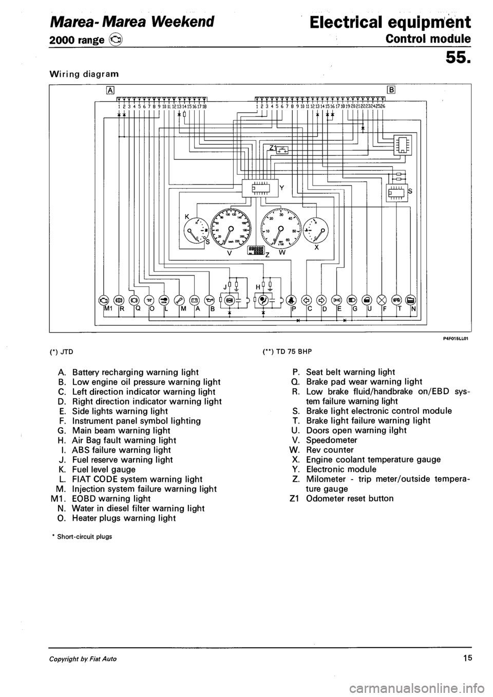
Wiring diagram
.mrmmmL 18 3 4 5 6 7 8 9 10 U 1213 1415161718 |TTTTrTrrrrTTTTT1.TTTTT1pmL 18 3 4 5 6 7 8 9 10 11 121314151617181920213223248586
n ti
O Mill
(*) JTD
A. Battery recharging warning light
B. Low engine oil pressure warning light
C. Left direction indicator warning light
D. Right direction indicator warning light
E. Side lights warning light
F. Instrument panel symbol lighting
G. Main beam warning light
H. Air Bag fault warning light
I. ABS failure warning light
J. Fuel reserve warning light
K. Fuel level gauge
L. FIAT CODE system warning light
M. Injection system failure warning light
M1. EOBD warning light
N. Water in diesel filter warning light
O. Heater plugs warning light
(**) TD 75 BHP
P. Seat belt warning light
Q. Brake pad wear warning light
R. Low brake fluid/handbrake on/EBD sys
tem failure warning light
S. Brake light electronic control module
T. Brake light failure warning light
U. Doors open warning ilght
V. Speedometer
W. Rev counter
X. Engine coolant temperature gauge
Y. Electronic module
Z. Milometer - trip meter/outside tempera
ture gauge
Z1 Odometer reset button
* Short-circuit plugs
Copyright by Fiat Auto 15
Page 146 of 330
Electrical equipment
Instrument panel
Marea- Marea Weekend
2000 range ©
55.
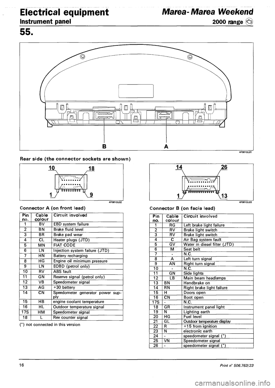
Rear side (the connector sockets are shown)
Connector A (on front lead) Connector B (on facia lead)
Pin no. Cable colour Circuit involved
1 BV EBD system failure
2 BN Brake fluid level
3 BR Brake pad wear
4 CL Heater plugs (JTD)
5 MN FIAT CODE
6 LN Injection system failure (JTD)
7 HN Battery recharging
8 HG Engine oil minimum pressure
9 LN EOBD (petrol only)
10 RV ABS fault
11 GN Reserve signal (petrol only)
12 VB Speedometer signal
13 AG +30 battery
14 CN Speedometer generator power supply
15 HB engine coolant temperature
16 HL Outdoor temperature signal
17S HM Speedometer signal
18 L Rev counter signal
(*) not connected in this version
Pin no. Cable colour Circuit involved
1 RG Left brake light failure
2 RV Brake light switch
3 RV Brake light switch
4 C Air Bag system fault
5 GV Water in diesel filter (JTD)
6 M Seat belt
7 -N.C.
8 A Left turn signal
9 AN Right turn signal
10 -N.C.
11 GN Side lights
12 LB Main beam headlamps
13 BN Handbrake on
14 RN Right brake light failure
15 H Doors open
16 CN Boot open
17S -N.C.
18 GR Instrument panel light
19 N Lighting earth
20 HG Fuel level
21 GL Outdoor temperature display
22 R +15 from ignition
23 N electronic earth
24 -speedometer signal (*)
25 VN Speedometer signal
26 -speedometer signal (*)
16 Print n° 506.763/23