check engine FIAT MAREA 2001 1.G Workshop Manual
[x] Cancel search | Manufacturer: FIAT, Model Year: 2001, Model line: MAREA, Model: FIAT MAREA 2001 1.GPages: 330
Page 28 of 330
Marea- Marea Weekend Technical Data
2000 range (Q) Engine: cylinder head and valve gear components
OO.io
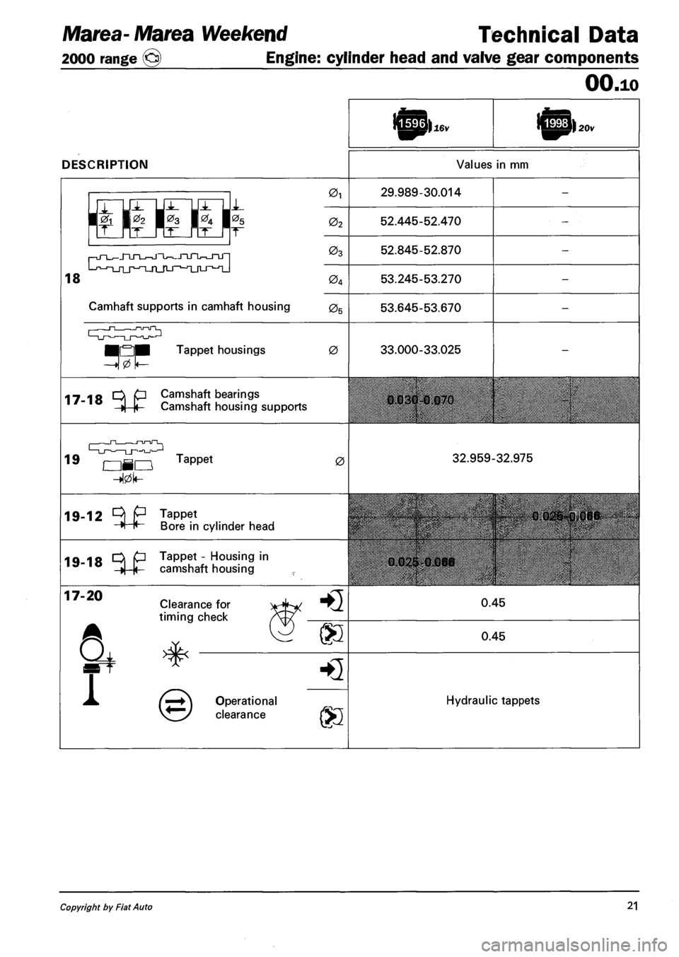
DESCRIPTION
16v 20v
Values in mm
r-jn_J_jnjT_^jnJ-^JTjnr^-JTJ-|
L-f,-n_rij^-T_n_rLj-,-jijtj_^^
0i 29.989-30.014
02 52.445-52.470
03 52.845-52.870
04 53.245-53.270
Camhaft supports in camhaft housing 05 53.645-53.670
n—,—nnTL
•QM Tappet housings 0 33.000-33.025
17-18 ^ P Camshaft bearings
»| |< Camshaft housing supports 0.030-0.070
19
—-^_J~l— r-u—u~~l_ —LJ—^—LJ-i-a_r>—1-1
OHO Tappet 0 32.959-32.975
19-12 ^ P Tappet
H H Bore in cyli cylinder head
19-18 ^ P Tappet - Housing in ,5'"10 »| |< camshaft housing 0.02S-0.066
0.025-0,066
17-20 Clearance for
timing check HQ 0.45
® 0.45
1
HQ
Operational
clearance ®
Hydraulic tappets
Copyright by Fiat Auto 21
Page 33 of 330
Technical Data Marea-Marea Weekend
Engine: cooling system • fuel system 2000 range (§)
OO.io
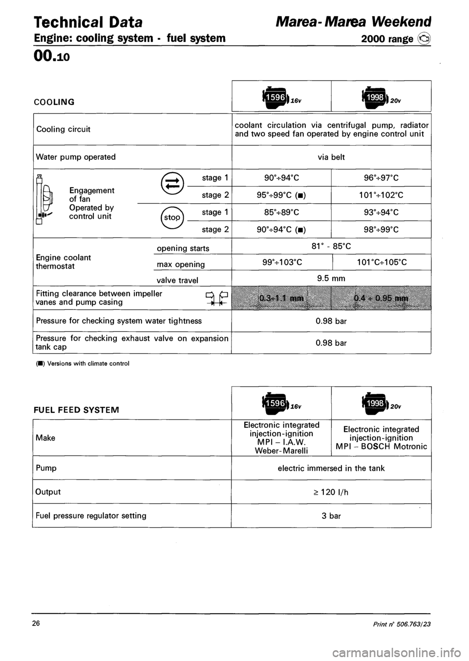
COOLING
Cooling circuit coolant circulation via centrifugal pump, radiator
and two speed fan operated by engine control unit
Water pump operated via belt
fl (^+\ STA9E 1 90°H-94°C 96°+97T
^ Engagement vj^/ ?
of fan stage Z 95°+99°C (•) 101+102°C
\f Operated by v .
control unit (s\oo\ 9 85V89X 93°-H94T
• v y
v—' stage 2 90°+94°C (•) 98+99T
opening starts 81° - 85°C
Engine coolant
thermostat rnax opening 99+103°C 101DC+105'C
valve travel 9.5 mm
Fitting clearance between impeller p
vanes and pump casing j |< 0.3:1.1 mm 0.4 : 0.95 mm
Pressure for checking system water tightness 0.98 bar
Pressure for checking exhaust valve on expansion
tank cap 0.98 bar
(•) Versions with climate control
FUEL FEED SYSTEM
Make
Electronic integrated
injection-ignition
MPI - I.A.W.
Weber-Marelli
Electronic integrated
injection-ignition
MPI - BOSCH Motronic
Pump electric immersed in the tank
Output > 120 l/h
Fuel pressure regulator setting 3 bar
26 Print n° 506.763/23
Page 69 of 330
Marea- Marea Weekend • ^ Engine
2000 range (Q) Fuel feed system
10.
ENGINE MANAGEMENT SYSTEM
The Marea-Marea Weekend 1596 16v has a 4 cylinder in line engine, with 16 valves, 1596 cc, twin over
head camshaft and a Marelli IAW 4EF integrated electronic injection/ignition system.
The fuel system differs from the one described for the 1581 16v "99 range" version through the addition
of several variants to make it compatible with the EEC Stage 3 EOBD regulations.
The main modifications to the system can be summarized as follows:
- Engine management control unit with IAW 4EF
- Catalytic converter near the exhaust manifold to take maximum advantage of the heat of the gases.
- Two Lambda senors, one upstream (front) and one downstream (rear) which check the quality of the
exhaust gases and the operation of the catalyzer.
- Adoption of a timing sensor on the inlet side timing pulley.
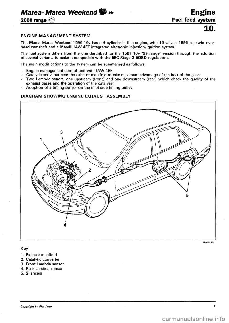
DIAGRAM SHOWING ENGINE EXHAUST ASSEMBLY
1. Exhaust manifold
2. Catalytic converter
3. Front Lambda sensor
4. Rear Lambda sensor
5. Silencers
Copyright by Fiat Auto 1
Page 75 of 330
Marea- Marea Weekend •
2000 range ©
16v Engine
Fuel feed system
10.
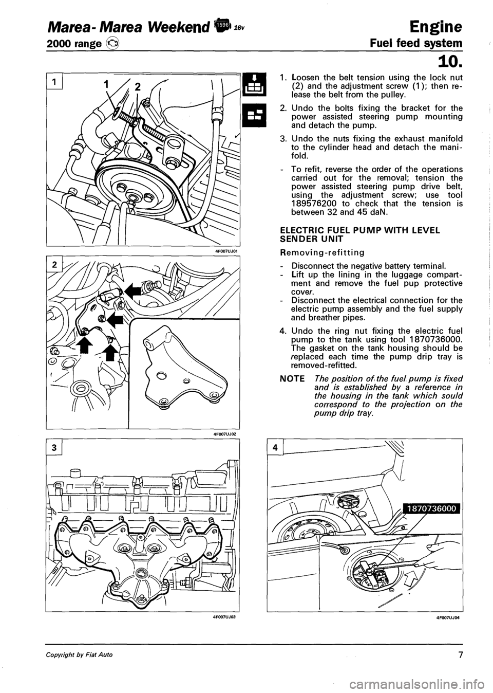
1. Loosen the belt tension using the lock nut
(2) and the adjustment screw (1); then re
lease the belt from the pulley.
2. Undo the bolts fixing the bracket for the
power assisted steering pump mounting
and detach the pump.
3. Undo the nuts fixing the exhaust manifold
to the cylinder head and detach the mani
fold.
- To refit, reverse the order of the operations
carried out for the removal; tension the
power assisted steering pump drive belt,
using the adjustment screw; use tool
189576200 to check that the tension is
between 32 and 45 daN.
ELECTRIC FUEL PUMP WITH LEVEL
SENDER UNIT
Removing-refitting
- Disconnect the negative battery terminal.
- Lift up the lining in the luggage compart
ment and remove the fuel pup protective
cover.
- Disconnect the electrical connection for the
electric pump assembly and the fuel supply
and breather pipes.
4. Undo the ring nut fixing the electric fuel
pump to the tank using tool 1870736000.
The gasket on the tank housing should be
replaced each time the pump drip tray is
removed-refitted.
NOTE The position of the fuel pump is fixed
and is established by a reference in
the housing in the tank which sou Id
correspond to the projection on the
pump drip tray.
Copyright by Fiat Auto 7
Page 78 of 330
Marea- Marea Weekend & Engine
2000 range (§) Fuel feed system
ENGINE MANAGEMENT SYSTEM
Foreword
The Marea-Marea Weekend 1998 20v is equipped with a 5 cylinder in line engine with 20 valves, 1998
cc, twin overhead camshaft and a Bosch ME3.1 integrated electronic injection/ignition system.
The fuel system differs from the one described for the 1998 20v "99 range" version through the addition
of several variants to make it compatible with the EEC Stage 3 EOBD regulations.
The main modifications to the system can be summarized as follows:
- Catalytic converter near the exhaust manifold to take maximum advantage of the heat of the gases.
- Two Lambda sensors, one upstream (front) and one downstream (rear) which check the quality of the
exhaust gases and the operation of the catalyzer.
- Adoption of an accelerometre sensor on the right shock absorber turret, used to distinguish between
engine torque variations doe to the uneveness of the road surface and those due to failed ignition in
the combustion chamber (misfire).
- Adoption of a timing sensor on the inlet side timing pulley.
- Multi-purpose valve on the tank to prevent leaks.
- Adoption of raipd attachment connectors for the anti-evaporation system pipes.
- Cap on the fuel filler with an attachment cable.
For further information on the fuel system, refer to publication 507137.
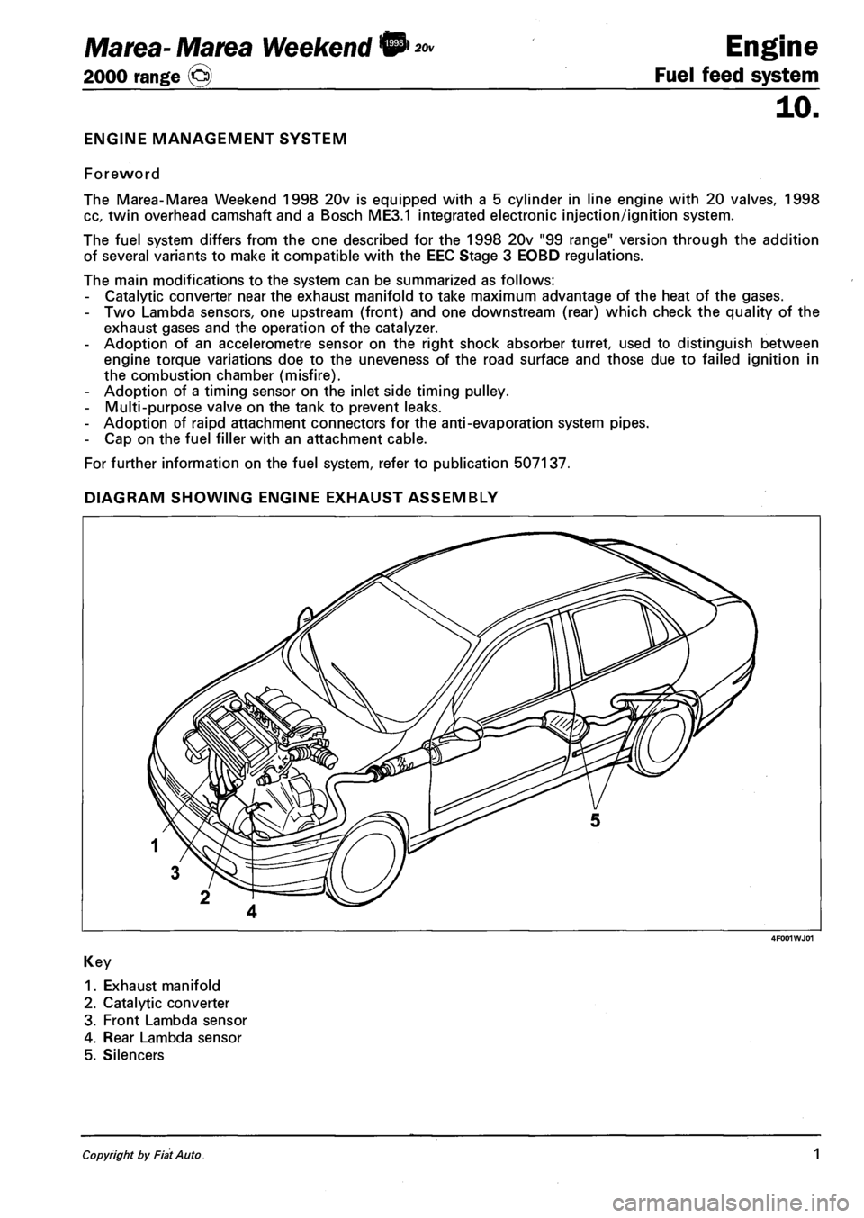
DIAGRAM SHOWING ENGINE EXHAUST ASSEMBLY
4F001WJ01
Key
1. Exhaust manifold
2. Catalytic converter
3. Front Lambda sensor
4. Rear Lambda sensor
5. Silencers
Copyright by Fiat Auto 1
Page 92 of 330
Fuel feed system
Engine Marea- Marea Weekend © ™
2000 range @
10.
The control unit autodiagnostic system checks the signals coming from the sensors and compares them
with the figures allowed:
- signalling faults during starting
- warning light on for 4 seconds indicates test stage
- warning light off after 4 seconds indicates no fault with components that could alter the pollution con
trol standard figures
- warning light on after 4 seconds indicates fault.
- signalling faults during operation
- warning light on indicates fault
- warning light off indicates no fault with components that could alter the pollution control standard fig
ures.
- recovery
- from time to time, the control unit defines the type of recovery according to the components which are
faulty
- the recovery parameters are managed by components which are not faulty.
Control of cylinder balancing during idling
According to the signals coming from the sensors, the injection control unit controls the idle speed torque,
altering the injector operating times.
Control of irregular operation
Depending on the signals coming from the sensors, the injection control unit corrects the amount of fuel
to be injected in order to improve driveability and reduce jerking whilst driving.
The correction is achieved through the fuel pressure regulator and by varying the injector operating times.
Control of electrical balance
According to the battery voltage, the injection control unit alters the idle speed, to guarantee a sufficient
current supply from the alternator in situations where the consumers are absorbing a great deal of power.
The variation in the idle speed is achived by regulating the fuel pressure and altering the injector operat
ing times.
VGT variable geometry turbocharger control (1910 JTD 110 CV)
The injection control unit processes the signal coming from the supercharging sensor, at the various en
gine operating speeds, and determines the quantity of fuel to be injected, acting on the fuel pressure
regulator and the injector opening times.
In addition, through the solenoid valve, the control unit regulates the geometry of the turbine in order to
ensure optimum performance in all operating conditions.
Turbocharger waste gate valve control (1910 JTD 100 CV)
At the various engine operating speeds, the injection control unit processes the signal coming from the
supercharging sensor and determines the amount of fuel to inject, acting on the fuel pressure regulator
and the injector opening times.
In addition, the control unit controls the opening of the turbocharger waste gate valve, via the solenoid
valve, in order to ensure excellent performance in all operating conditions.
Control of throttle closing when engine is switched off
When the engine is switched off (ignition key in OFF position) the injection control unit closes the throt
tle valve located on the air intake duct via the special solenoid valve.
This action makes it possible to limit the tiresome shuddering of the engine whilst it is switching off.
6 .i. V!-01-.Cancelftand replaces Print n° 506.763/25
Page 98 of 330
Engine
Fuel feed system
10.
4F012XJ03
Marea- Matea Weekend 9 ™
2000 range (Q)
RPM SENSOR
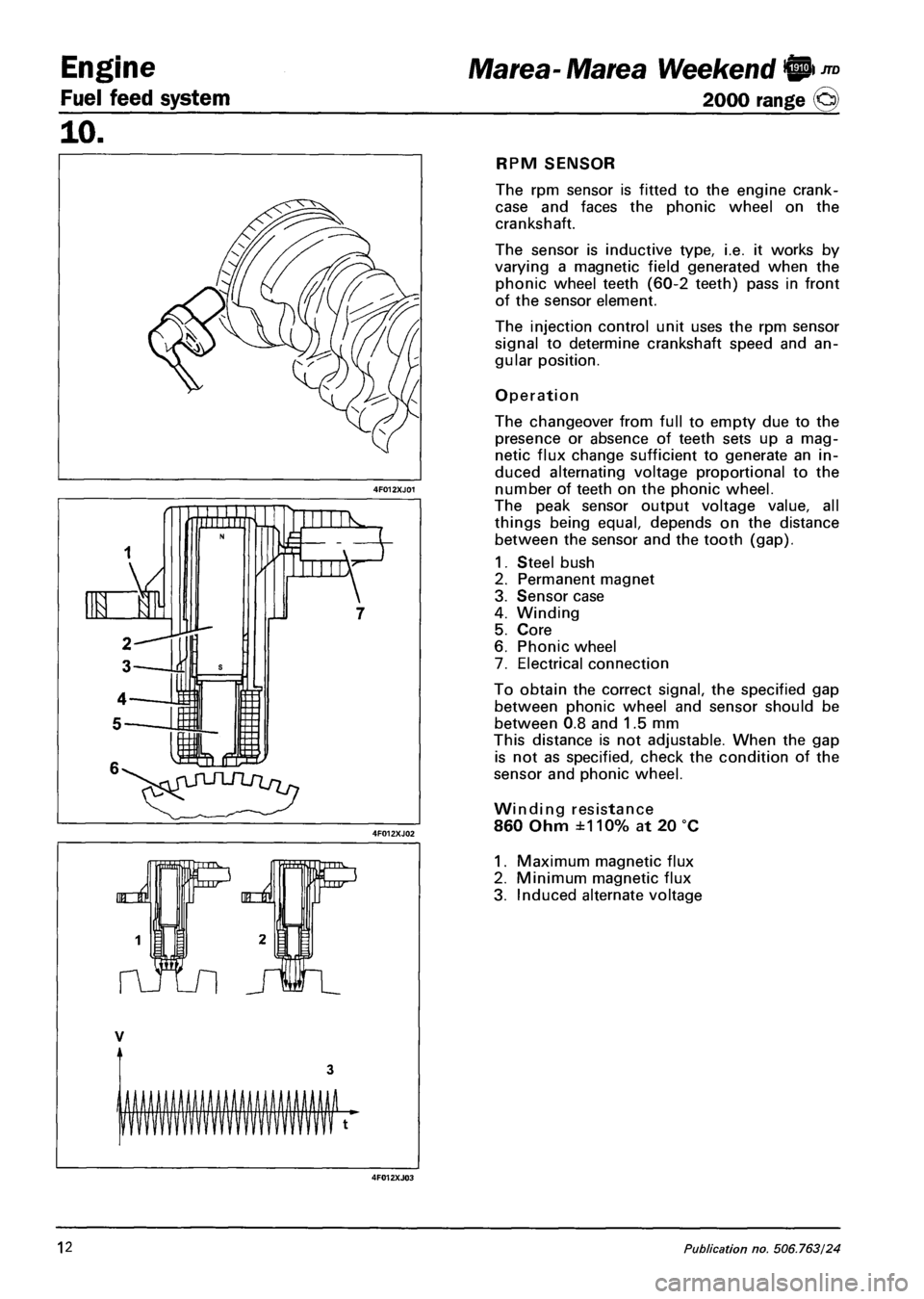
The rpm sensor is fitted to the engine crank-
case and faces the phonic wheel on the
crankshaft.
The sensor is inductive type, i.e. it works by
varying a magnetic field generated when the
phonic wheel teeth (60-2 teeth) pass in front
of the sensor element.
The injection control unit uses the rpm sensor
signal to determine crankshaft speed and an
gular position.
Operation
The changeover from full to empty due to the
presence or absence of teeth sets up a mag
netic flux change sufficient to generate an in
duced alternating voltage proportional to the
number of teeth on the phonic wheel.
The peak sensor output voltage value, all
things being equal, depends on the distance
between the sensor and the tooth (gap).
1. Steel bush
2. Permanent magnet
3. Sensor case
4. Winding
5. Core
6. Phonic wheel
7. Electrical connection
To obtain the correct signal, the specified gap
between phonic wheel and sensor should be
between 0.8 and 1.5 mm
This distance is not adjustable. When the gap
is not as specified, check the condition of the
sensor and phonic wheel.
Winding resistance
860 Ohm ±110% at 20 °C
1. Maximum magnetic flux
2. Minimum magnetic flux
3. Induced alternate voltage
12 Publication no, 506.763/24
Page 103 of 330
Marea-Marea Weekend 9 -™ Engine
2000 range (j§) Fuel feed system
10.
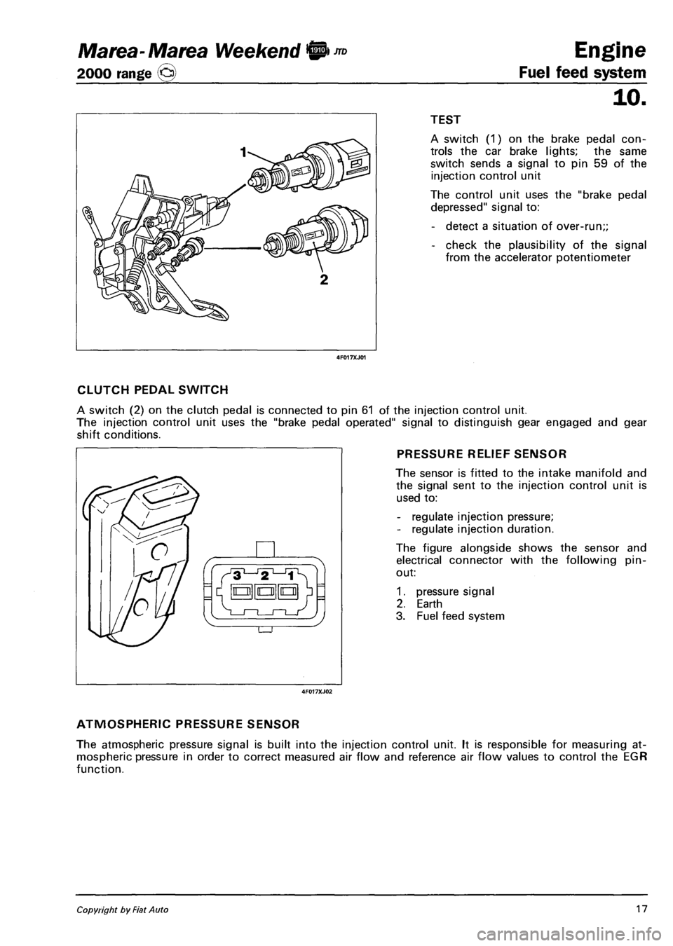
I I TEST
4F017XJ01
A switch (1) on the brake pedal con
trols the car brake lights; the same
switch sends a signal to pin 59 of the
injection control unit
The control unit uses the "brake pedal
depressed" signal to:
- detect a situation of over-run;;
- check the plausibility of the signal
from the accelerator potentiometer
CLUTCH PEDAL SWITCH
A switch (2) on the clutch pedal is connected to pin 61 of the injection control unit.
The injection control unit uses the "brake pedal operated" signal to distinguish gear engaged and gear
shift conditions.
PRESSURE RELIEF SENSOR
The sensor is fitted to the intake manifold and
the signal sent to the injection control unit is
used to:
- regulate injection pressure;
- regulate injection duration.
The figure alongside shows the sensor and
electrical connector with the following pin-
out:
1. pressure signal
2. Earth
3. Fuel feed system
ATMOSPHERIC PRESSURE SENSOR
The atmospheric pressure signal is built into the injection control unit. It is responsible for measuring at
mospheric pressure in order to correct measured air flow and reference air flow values to control the EGR
function.
Copyright by Fiat Auto 17
Page 105 of 330
Marea- Marea Weekend 9 ™
2000 range (Q)
4F019XJ01
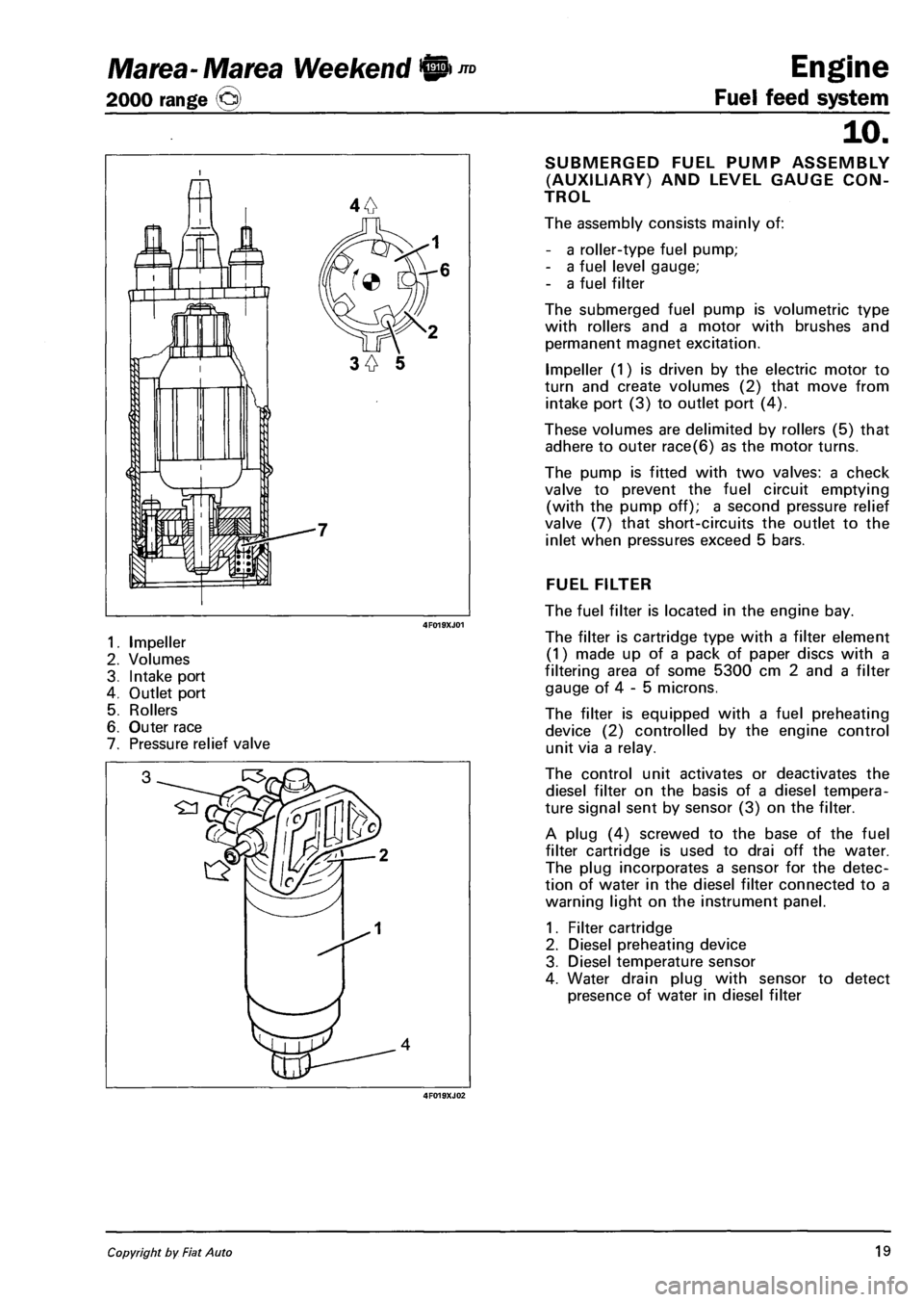
1. Impeller
2. Volumes
3. Intake port
4. Outlet port
5. Rollers
6. Outer race
7. Pressure relief valve
4F019XJ02
Engine
Fuel feed system
10.
SUBMERGED FUEL PUMP ASSEMBLY
(AUXILIARY) AND LEVEL GAUGE CON
TROL
The assembly consists mainly of:
- a roller-type fuel pump;
- a fuel level gauge;
- a fuel filter
The submerged fuel pump is volumetric type
with rollers and a motor with brushes and
permanent magnet excitation.
Impeller (1) is driven by the electric motor to
turn and create volumes (2) that move from
intake port (3) to outlet port (4).
These volumes are delimited by rollers (5) that
adhere to outer race(6) as the motor turns.
The pump is fitted with two valves: a check
valve to prevent the fuel circuit emptying
(with the pump off); a second pressure relief
valve (7) that short-circuits the outlet to the
inlet when pressures exceed 5 bars.
FUEL FILTER
The fuel filter is located in the engine bay.
The filter is cartridge type with a filter element
(1) made up of a pack of paper discs with a
filtering area of some 5300 cm 2 and a filter
gauge of 4 - 5 microns.
The filter is equipped with a fuel preheating
device (2) controlled by the engine control
unit via a relay.
The control unit activates or deactivates the
diesel filter on the basis of a diesel tempera
ture signal sent by sensor (3) on the filter.
A plug (4) screwed to the base of the fuel
filter cartridge is used to drai off the water.
The plug incorporates a sensor for the detec
tion of water in the diesel filter connected to a
warning light on the instrument panel.
1. Filter cartridge
2. Diesel preheating device
3. Diesel temperature sensor
4. Water drain plug with sensor to detect
presence of water in diesel filter
Copyright by Fiat Auto 19
Page 123 of 330
Marea-Marea Weekend H nD Engine
2000 range (Q) Fuel feed system
10.
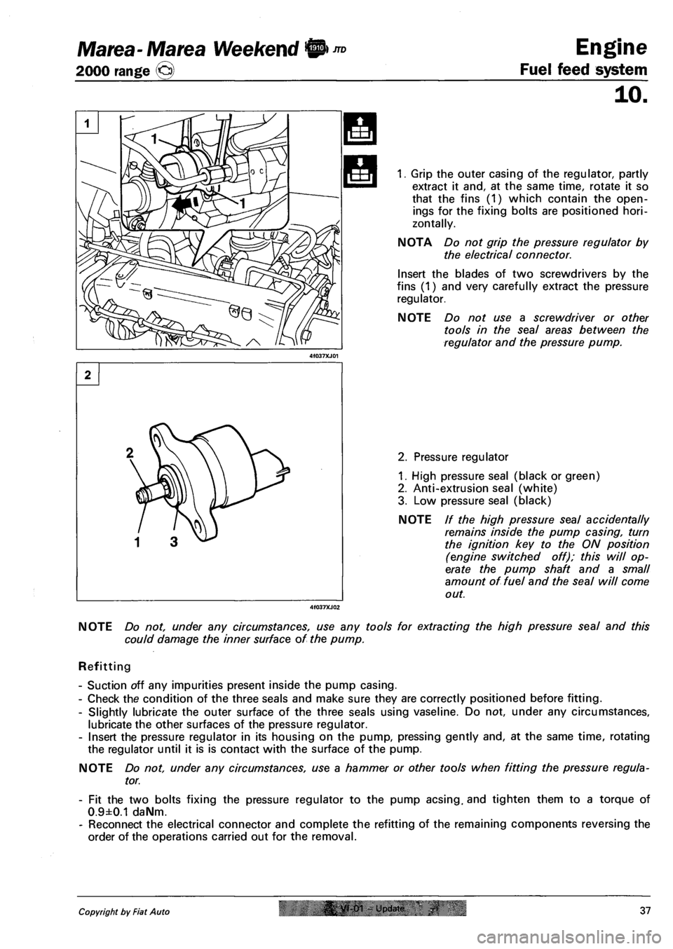
1. Grip the outer casing of the regulator, partly
extract it and, at the same time, rotate it so
that the fins (1) which contain the open
ings for the fixing bolts are positioned hori
zontally.
NOTA Do not grip the pressure regulator by
the electrical connector.
Insert the blades of two screwdrivers by the
fins (1) and very carefully extract the pressure
regulator.
NOTE Do not use a screwdriver or other
tools in the seal areas between the
regulator and the pressure pump.
2. Pressure regulator
1. High pressure seal (black or green)
2. Anti-extrusion seal (white)
3. Low pressure seal (black)
NOTE // the high pressure seal accidentally
remains inside the pump casing, turn
the ignition key to the ON position
(engine switched off); this will op
erate the pump shaft and a small
amount of fuel and the seal will come
out.
NOTE Do not, under any circumstances, use any tools for extracting the high pressure seal and this
could damage the inner surface of the pump.
Refitting
- Suction off any impurities present inside the pump casing.
- Check the condition of the three seals and make sure they are correctly positioned before fitting.
- Slightly lubricate the outer surface of the three seals using vaseline. Do not, under any circumstances,
lubricate the other surfaces of the pressure regulator.
- Insert the pressure regulator in its housing on the pump, pressing gently and, at the same time, rotating
the regulator until it is is contact with the surface of the pump.
NOTE Do not, under any circumstances, use a hammer or other tools when fitting the pressure regula
tor.
- Fit the two bolts fixing the pressure regulator to the pump acsing. and tighten them to a torque of
0.9±0.1 daNm.
- Reconnect the electrical connector and complete the refitting of the remaining components reversing the
order of the operations carried out for the removal.
Copyright by Fiat Auto |& yt-01 - Update 37