turn signal FIAT MAREA 2001 1.G Workshop Manual
[x] Cancel search | Manufacturer: FIAT, Model Year: 2001, Model line: MAREA, Model: FIAT MAREA 2001 1.GPages: 330
Page 89 of 330
Ma tea- Marea Weekend 9 ™
2000 range (Q) Fuel feed system
Engine
10.
Control of injected fuel quantity
The control unit controls the fuel pressure regulator and injectors on the basis of output signals from the
accelerator pedal potentiometer, flow meter and rpm sensor.
The timing and thus the injection sequence are determined when the engine is started up using signals
from the rpm and timing sensor (synchronisation stage); injection timing is then implemented using the
rpm sensor signal alone and considering a injection sequence of 1 -3-4-2.
The control unit inhibits injection in the following cases:
- fuel pressure level greater than 1500 bars;
- fuel pressure level lower than 120 bars;
- engine speed higher than 6000 rpm.
When the engine has warmed up, maximum injection duration (injector opening time) is 1500 ns, but it
can reach 3000 ns during the start-up stage.
Control of injection advance
The electronic control unit determines injection advance mainly on the basis of the quantity of fuel to be
injected.
The injection advance is then corrected on the basis of coolant temperature and speed in order to com
pensate for ignition delays due to low temperatures in the combustion chamber during warm-up.
The optimum injection point is also processed to ensure driving comfort and emission limits laid down by
Euro 3 legislation.
Control of injection pressure
This control is of particular importance because injection pressure influences the following parameters:
- amount of fuel taken into the cylinders for the same injection time duration;
- injected fuel nebulation;
- spray penetration;
- lag between electrical control to injection and actual injection start and end times.
The above parameters engine behaviour significantly, particularly in terms of power output, exhaust emis
sions, noise levels and handling.
The injection control unit controls the pressure governor on the basis of engine load to obtain an optimal
line pressure at all times.
When the engine is cold, injection pressure is corrected on the basis of engine speed and engine coolant
temperature to meet engine needs at different operating temperatures.
Control of auxiliary fuel pump
The auxiliary fuel pump submerged in the tank is supplied by the injection control unit by means of a relay
when the ignition key is turned on.
Fuel supply to the pump is inhibited when one of the following condition occurs:
- when the ignition has been turned on for a certain length of time without the engine running;
- if the inertia switch cuts in.
Control of injection during over-run (cut-off)
The fuel cut-off strategy is implemented when the injection control unit receives information that the ac
celerator pedal has been released from the potentiometer.
Under these conditions, the control unit cuts off the fuel supply to the injectors and restores it before idle
speed is reached.
Copyright by Fiat Auto 3
Page 90 of 330
Fuel feed system
Engine Marea- Marea Weekend 9 ™
2000 range (Q)
10.
Control of idle speed
On the basis of signals from the rpm sensor and engine coolant temperature sensor, the injection control
unit controls the pressure governor and alters the injector control times to maintain idle speed stable at all
times.
Under certain conditions, the idle speed control unit also considers battery voltage.
Control of maximum speed limitation
According to rpm level, the injection control unit limits maximum speed by means of two types of inter
vention:
- as maximum speed approaches, it reduces the amount of fuel injected to reduce line pressure;
- when maximum speed is exceeded, it inhibits operation of the auxiliary pump and injectors.
Control of maximum torque limitation
On the basis of rpm level, the injection control unit computes limit torque and maximum permitted fume
index parameters on the basis of predefined, stored maps.
It then corrects the above parameters using engine coolant temperature and car speed data. The resulting
values are then used to modulate the amount of fuel to be injected by adjusting the pressure regulator and
injectors.
Control of fuel temperature
The injection control uint is kept constantly informed of fuel temperature by a sensor on the return mani
fold.
If fuel temperature exceeds a set value (about 110 °C), the control unit reduces line pressure by adjusting
the pressure governor, leaving injection times unaltered.
Control of coolant temperature
The injection control unit is constantly informed of coolant temperature by a sensor on the thermostat.
If engine coolant temperature or air conditioning fluid pressure exceeds certain levels, the control unit
performs the following actions:
- It reduces the amount of fuel injected by adjusting the pressure governor and injectors (power reduc
tion);
- it controls the engine radiator cooling fan.
Control of glow plugs
The injection control unit controls operation of the glow plug preheating control unit to bring the tem
perature in the combution chambers up to levels that promote fuel self-ignition and thus make start-up
easier.
The control unit controls the operation of the glow plug control unit for a certain time both before (pre
heating) and after (postheating) engine start-up and also controls activation of the warning light on the
control panel.
Preheating, postheating and glow plug warning light activation times vary according to engine coolant
temperature.
4 Publication no. 506.763/24
Page 91 of 330
![FIAT MAREA 2001 1.G Workshop Manual Marea-Marea Weekend 9]
2000 range (j§)
I) JTD
Fuel feed system
Engine
10.
Exhaust fumes control
Through this function the injection control unit limits any exhaust fumes that could be produce FIAT MAREA 2001 1.G Workshop Manual Marea-Marea Weekend 9]
2000 range (j§)
I) JTD
Fuel feed system
Engine
10.
Exhaust fumes control
Through this function the injection control unit limits any exhaust fumes that could be produce](/img/10/4653/w960_4653-90.png)
Marea-Marea Weekend 9]
2000 range (j§)
I) JTD
Fuel feed system
Engine
10.
Exhaust fumes control
Through this function the injection control unit limits any exhaust fumes that could be produced during
transition speeds.
To satisy these requirements the control unit processes the signals supplied by the accelerator pedal po
tentiometer, the rpm sensor and the air flow meter and controls the fuel pressure regulator and the injec
tors to meter the correct amount of fuel to inject.
Exhaust gas recirculation control
On the basis of the signals supplied by the rpm sensor, intake air quantity sensor, engine coolant tempe
rature sensor and accelerator pedal position sensor, the control unit calculates the operating times for the
EGR valve so that the exhaust gases are partly recirculated in certain engine operating conditions in line
with Euro 3 pollution control standards.
Air conditioning system engagement control
The injection control unit manages the operation of the air conditioning system compressor electro
magnet coupling following a logic aimed at preventing operating conditions that would adversely affect
engine performance.
- When the compressor is switched on the injection control unit increases the quantity of fuel during
idling to allow the engine to adjust to the increased power requirements and momentarily interrupts the
supply to the compressor in high engine power requirement conditions (strong acceleration).
Engine immobilizer function control
The system is equipped with an engine immobilizer function. This function is achieved through the pre
sence of a specific control unit (Fiat CODE), capable of conversing with the injection control unit and an
electronic key with a special transmitter for sending a recognition code.
Each time the key is turned to the OFF position, the Fiat CODE system completely deactivates the injecti
on control unit.
When the key is turned to the ON position the following operations take place, in order:
1. the injection control unit (whose memory contains a secret code) sends the Fiat CODE control unit a
request to send the secret code to deactivate the immobilizer functions;
2. the Fiat CODE control unit responds by only sending the secret code after, in turn, having received the
recognition code transmitted by the ignition key;
3. the recognition of the secret code allows the deactivation of the injection control unit immobilizer func
tion and its normal operation.
Autodiagnosis
The complete electronic fault diagnosis of the injection system is carried out by connecting the special
equipment (EXAMINER or EXAMINER PLUS) to the standardized diagnostic socket (EOBD).
The system is also equipped with a self-diagnostic function which recognizes, memorizes and signals any
faults.
If a fault is detected in the sensors or actuators, the recovery strategy is immediately activated in order to
ensure that the engine functions at an acceptable level. The vehicle can be driven to a service centre for
the appropriate repairs to be carried out.
Copyright by Fiat Auto 5
Page 101 of 330
Marea- Marea Weekend 9™
2000 range (§)
4F015XJ03
Engine
Fuel feed system
ijo.
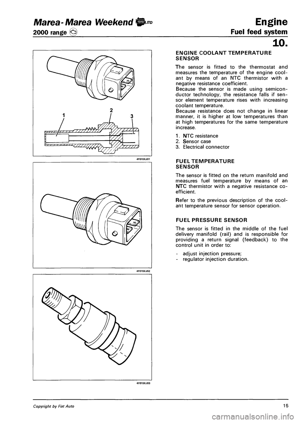
ENGINE COOLANT TEMPERATURE
SENSOR
The sensor is fitted to the thermostat and
measures the temperature of the engine cool
ant by means of an NTC thermistor with a
negative resistance coefficient.
Because the sensor is made using semicon
ductor technology, the resistance falls if sen
sor element temperature rises with increasing
coolant temperature.
Because resistance does not change in linear
manner, it is higher at low temperatures than
at high temperatures for the same temperature
increase.
1. NTC resistance
2. Sensor case
3. Electrical connector
FUEL TEMPERATURE
SENSOR
The sensor is fitted on the return manifold and
measures fuel temperature by means of an
NTC thermistor with a negative resistance co
efficient.
Refer to the previous description of the cool
ant temperature sensor for sensor operation.
FUEL PRESSURE SENSOR
The sensor is fitted in the middle of the fuel
delivery manifold (rail) and is responsible for
providing a return signal (feedback) to the
control unit in order to:
- adjust injection pressure;
- regulator injection duration.
Copyright by Fiat Auto 15
Page 102 of 330
![FIAT MAREA 2001 1.G Workshop Manual Engine
Fuel feed system
JTD Marea-Marea Weekend ©
2000 range ©
10.
iH
ft
B I 0 ] I D
[ 0 0 1 1
D
0 1 <fi=2 1 1 15J
GLOW PLUG PREHEATING CONTROL
UNIT
The glow plugs are controlled by mea FIAT MAREA 2001 1.G Workshop Manual Engine
Fuel feed system
JTD Marea-Marea Weekend ©
2000 range ©
10.
iH
ft
B I 0 ] I D
[ 0 0 1 1
D
0 1 <fi=2 1 1 15J
GLOW PLUG PREHEATING CONTROL
UNIT
The glow plugs are controlled by mea](/img/10/4653/w960_4653-101.png)
Engine
Fuel feed system
JTD Marea-Marea Weekend ©
2000 range ©
10.
iH
ft
B I 0 ] I D
[ 0 0 1 1
D
0 1
UNIT
The glow plugs are controlled by means of a
preheating control unit under the direct con
trol of the injection control unit.
The preheating control unit contains a smart
relay that sends a return response (feedback)
to the injection control unit, which is thus in
formed of faults in the preheating control unit
or glow plug short-circuits to earth.
The figure shows the connectors on the base
of the preheating control unit and the pin-out
1. Earth
2. Injection control unit (pin 22)
3. Power supply from main injection relay
4. Not connected
5. Injection control unit (pin 62)
8. Positive from battery (+30)
G. Glow plugs (only four outputs are used)
ACCELERATOR
PEDAL POTENTIOMETER
Accelerator pedal position is converted to an
electrical voltage signal and send to the injec
tion control unit by a potentiometer connected
to the accelerator pedal.
Accelerator pedal position is processed to
gether with rpm information to provide injec
tion times and pressure.
The sensor consists of a case (1) secured to
the pedal by a flange, which contains an axi-
ally-positioned shaft (2) connected to two
potentiometers (3): main and safety potenti
ometers.
A coil spring on the shaft ensures the correct
resistance to pressure while a second spring
ensures return upon release.
16 Publication no. 506.763/24
Page 105 of 330
Marea- Marea Weekend 9 ™
2000 range (Q)
4F019XJ01
1. Impeller
2. Volumes
3. Intake port
4. Outlet port
5. Rollers
6. Outer race
7. Pressure relief valve
4F019XJ02
Engine
Fuel feed system
10.
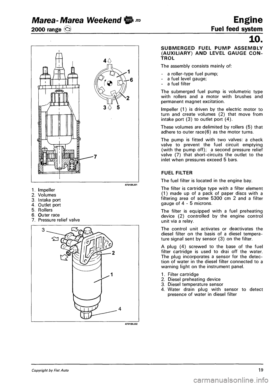
SUBMERGED FUEL PUMP ASSEMBLY
(AUXILIARY) AND LEVEL GAUGE CON
TROL
The assembly consists mainly of:
- a roller-type fuel pump;
- a fuel level gauge;
- a fuel filter
The submerged fuel pump is volumetric type
with rollers and a motor with brushes and
permanent magnet excitation.
Impeller (1) is driven by the electric motor to
turn and create volumes (2) that move from
intake port (3) to outlet port (4).
These volumes are delimited by rollers (5) that
adhere to outer race(6) as the motor turns.
The pump is fitted with two valves: a check
valve to prevent the fuel circuit emptying
(with the pump off); a second pressure relief
valve (7) that short-circuits the outlet to the
inlet when pressures exceed 5 bars.
FUEL FILTER
The fuel filter is located in the engine bay.
The filter is cartridge type with a filter element
(1) made up of a pack of paper discs with a
filtering area of some 5300 cm 2 and a filter
gauge of 4 - 5 microns.
The filter is equipped with a fuel preheating
device (2) controlled by the engine control
unit via a relay.
The control unit activates or deactivates the
diesel filter on the basis of a diesel tempera
ture signal sent by sensor (3) on the filter.
A plug (4) screwed to the base of the fuel
filter cartridge is used to drai off the water.
The plug incorporates a sensor for the detec
tion of water in the diesel filter connected to a
warning light on the instrument panel.
1. Filter cartridge
2. Diesel preheating device
3. Diesel temperature sensor
4. Water drain plug with sensor to detect
presence of water in diesel filter
Copyright by Fiat Auto 19
Page 135 of 330
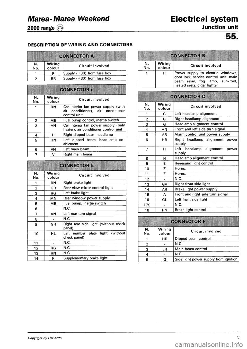
Marea-Marea Weekend
2000 range Q
DESCRIPTION OF WIRING AND CONNECTORS
CONNECTOR A
N.
No.
Wiring
colour Circuit involved
1 R Supply (+30) from fuse box
2 BR Supply (+30) from fuse box
CONNECTOR c
N. No.
Wiring colour Circuit involved
1 RN Car interior fan power supply (with
air conditioner), air conditioner
control unit
2 MB Fuel pump control, inertia switch
3 AN Car interior fan power supply (only heater), air conditioner control unit
4 H Right dipped beam headlamp
5 HN Left dipped beam, headllamp en
ablement
6 VN Left main beam
7 V Right main beam
CONNECTOR E
N.
No.
Wiring colour Circuit involved
1 RN Right brake light
2 GR Rear view mirror control light
3 RG Left brake light
4 MN Rear window power supply
5 MB Fuel pump, inertia switch
6 -N.C.
7 AN Left rear turn signal
8 -N.C.
9 GR Right rear side light (without check
panel)
10 HL Left number plate light (without
check panel)
11 -N.C.
12 RG N.C.
13 RN N.C.
14 R Supplementary brake light
Electrical system
Junction unit
55.
CONNECTOR B
N. No.
Wiring
colour Circuit involved
1 R Power supply to electric windows, door lock, service control unit, main beam relay, fog lamp, sun-roof, heated seats, cigar lighter
CONNECTOR D
N.
No.
Wiring colour Circuit involved
1 G Left headlamp alignment
2 G Right headlamp alignment
3 G Headlamp alignment control
4 AN Front and left side turn signal
5 AR Alarm control unit power supply
6 HB Right headlamp alignment power
supply
7 H Left headlamp alignment power
supply
8 H Headlamp alignment control
9 B Reversing light control
10 Z Horns.
11 Z Horns.
12 -N.C.
13 GV Right front side light
14 AR Brake light power supply
15 A Front and right side turn signal
16 GL Left front side light
17S -N.C.
18 RN Brake light control
CONNECTOR F
N.
No.
Wiring colour Circuit involved
1 HR Dipped beam control
2 -N.C.
3 LR Main beam control
4 -N.C.
5 G Side light power supply from ignition
Copyright by Fiat Auto 5
Page 136 of 330
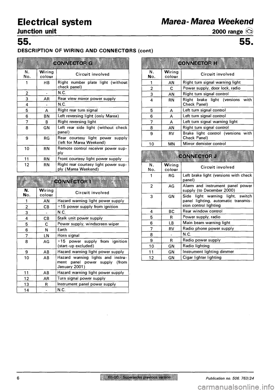
Electrical system
Junction unit
Marea- Marea Weekend
2000 range ©
55. 55.
DESCRIPTION OF WIRING AND CONNECTORS (cont)
CONNECTOR G
N.
No.
Wiring
colour Circuit involved
1 HB Right number plate light (without check panel)
2 -N.C.
3 AR Rear view mirror power supply
4 -N.C.
5 A Right rear turn signal
6 BN Left reversing light (only Marea)
7 B Right reversing light
8 GN Left rear side light (without check panel)
9 RG Rear courtesy light power supply (left for Marea Weekend)
10 RN Remote control receiver power supply
11 RN Front courtesy light power supply
12 RN Right rear courtesy light power supply (Marea Weekend)
CONNECTOR 1
N. No. Wiring
colour Circuit involved
1 AN Hazard warning light power supply
2 CB + 15 power supply from ignition
3 -N.C.
4 CB Stalk unit power supply
5 C Power supply, windscreen wiper
6 N Earth
7 LN Horn signal
8 AG + 15 power supply from ignition (start-up excluded)
9 AB Hazard warning light power supply
10 AB Hazard warning lights and instrument panel power supply (from January 2001)
11 AB Hazard warning light power supply
12 AR Turn signal power supply
13 R Instrument panel power supply
14 -N.C.
CONNECTOR H
N.
No.
Wiring
colour Circuit involved
1 AN Right turn signal warning light
2 C Power supply, door lock, radio
3 AN Right turn signal control
4 RN Right brake light (versions with Check Panel)
5 A Left turn signal control
6 A Left turn signal control
7 A Left turn signal warning light
8 AN Right turn signal control
9 RV Brake light control (versions with
Check Panel)
10 MN Mirror demister control
CONNECTOR J
N.
No.
Wiring colour Circuit involved
1 RG Left brake light (versions with check
panel)
2 AG Alarm and instrument panel power
supply (to December 2000)
3 GN Side light warning light, switch panel lighting, automatic transmission control lighting
4 BC Rear window control
5 R Power supply, radio
6 LB Main beam warning light
7 RV Radio phone power supply
8 -N.C.
9 R Radio power supply
10 GN Radio lighting
11 GN Instrument lighting dimmer
12 GN Cigar lighter lighting
6 Publication no. 506. 763/24
Page 137 of 330
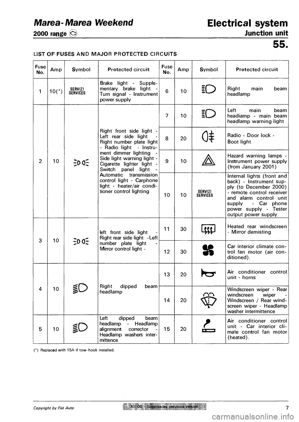
Marea-Marea Weekend Electrical system
2000 range @ Junction unit
55.
LIST OF FUSES AND MAJOR PROTECTED CIRCUITS
Fuse
No. Amp Symbol Protected circuit Fuse
No. Amp Symbol Protected circuit
1 ion SERVIZI SERVICES
Brake light - Supple
mentary brake light -
Turn signal - Instrument
power supply
6 10 ID Right main beam
headlamp
7 10 ID
Left main beam
headiamp - main beam
headlamp warning light
Right front side light -
Left rear side light
Right number plate light
- Radio light - Instru
8 20 0*
Radio - Door lock -
Boot light
2 10 3>
Side light warning light -
Cigarette lighter light -
Switch panel light -
9 10 A
Hazard warning lamps -
Instrument power supply
(from January 2001)
Automatic transmission
control light - Carphone
light - heater/air condi
tioner control lighting 10 10 SERVIZI SERVICES
Internal lights (front and
back) - Instrument sup
ply (to December 2000)
- remote control receiver
and alarm control unit
supply - Car phone
power supply - Tester
output power supply
3 10 -;o oi-
left front side light
Right rear side light -Left
11 30 Heated rear windscreen
- Mirror demisting
3 10 -;o oi-number plate light
Mirror control light -12 30 8
Car interior climate con
trol fan motor (air con
ditioned).
lO Right dipped beam
headlamp
13 20 Air conditioner control
unit - horns
4 10 lO Right dipped beam
headlamp
14 20
Windscreen wiper - Rear
windscreen wiper
Windscreen / Rear wind
screen wiper - Headlamp
washer intermittence
5 10 %o
Left dipped beam
headlamp - Headlamp
alignment corrector
Headlamp washers inter-
mittence
15 20 La
Air conditioner control
unit - Car interior cli
mate control fan motor
(heated).
(*) Replaced with 15A if tow-hook installed.
Copyright by Fiat Auto XII 00 - Supersedes previous version 7
Page 146 of 330
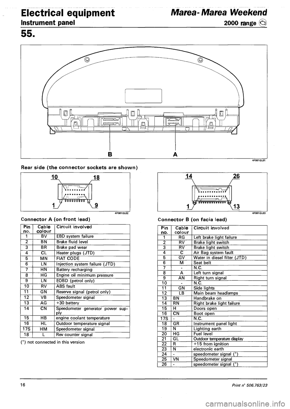
Electrical equipment
Instrument panel
Marea- Marea Weekend
2000 range ©
55.
Rear side (the connector sockets are shown)
Connector A (on front lead) Connector B (on facia lead)
Pin no. Cable colour Circuit involved
1 BV EBD system failure
2 BN Brake fluid level
3 BR Brake pad wear
4 CL Heater plugs (JTD)
5 MN FIAT CODE
6 LN Injection system failure (JTD)
7 HN Battery recharging
8 HG Engine oil minimum pressure
9 LN EOBD (petrol only)
10 RV ABS fault
11 GN Reserve signal (petrol only)
12 VB Speedometer signal
13 AG +30 battery
14 CN Speedometer generator power supply
15 HB engine coolant temperature
16 HL Outdoor temperature signal
17S HM Speedometer signal
18 L Rev counter signal
(*) not connected in this version
Pin no. Cable colour Circuit involved
1 RG Left brake light failure
2 RV Brake light switch
3 RV Brake light switch
4 C Air Bag system fault
5 GV Water in diesel filter (JTD)
6 M Seat belt
7 -N.C.
8 A Left turn signal
9 AN Right turn signal
10 -N.C.
11 GN Side lights
12 LB Main beam headlamps
13 BN Handbrake on
14 RN Right brake light failure
15 H Doors open
16 CN Boot open
17S -N.C.
18 GR Instrument panel light
19 N Lighting earth
20 HG Fuel level
21 GL Outdoor temperature display
22 R +15 from ignition
23 N electronic earth
24 -speedometer signal (*)
25 VN Speedometer signal
26 -speedometer signal (*)
16 Print n° 506.763/23