diagram FIAT MULTIPLA 2006 1.G Owners Manual
[x] Cancel search | Manufacturer: FIAT, Model Year: 2006, Model line: MULTIPLA, Model: FIAT MULTIPLA 2006 1.GPages: 266, PDF Size: 4.61 MB
Page 21 of 266
20
SAFETY
DEVICES
CORRECT USE
OF THE CAR
WARNING
LIGHTS AND
MESSAGES
IN AN
EMERGENCY
CAR
MAINTENANCE
TECHNICAL
SPECIFICATIONS
INDEX
DASHBOARD
AND CONTROLS
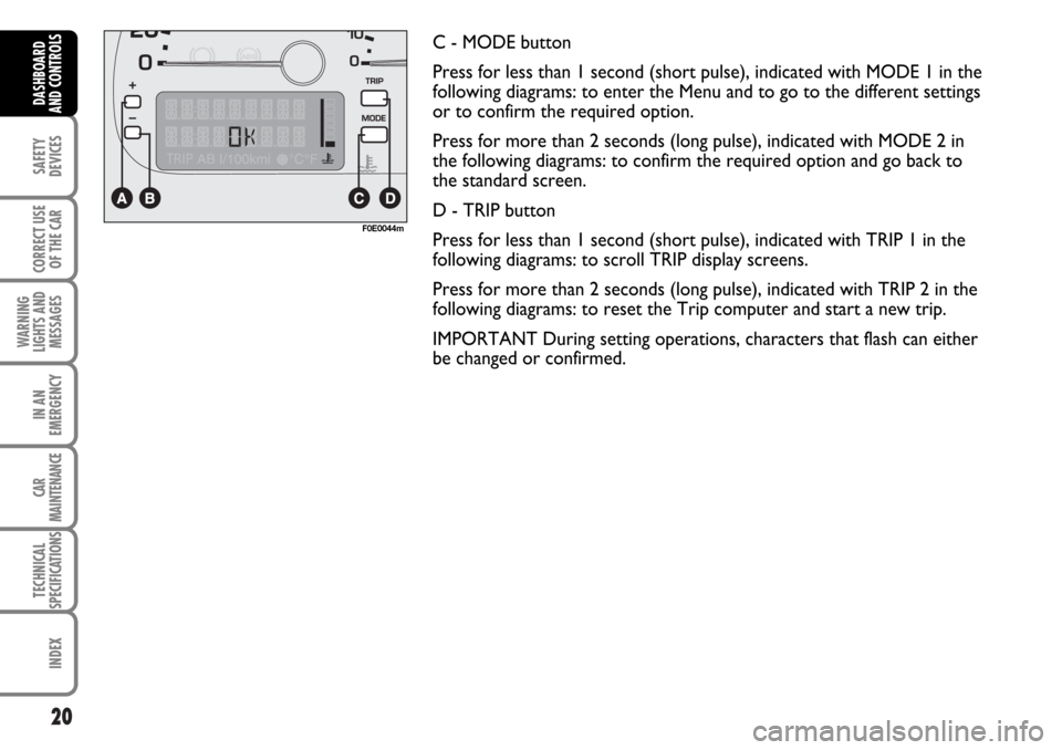
C - MODE button
Press for less than 1 second (short pulse), indicated with MODE 1 in the
following diagrams: to enter the Menu and to go to the different settings
or to confirm the required option.
Press for more than 2 seconds (long pulse), indicated with MODE 2 in
the following diagrams: to confirm the required option and go back to
the standard screen.
D - TRIP button
Press for less than 1 second (short pulse), indicated with TRIP 1 in the
following diagrams: to scroll TRIP display screens.
Press for more than 2 seconds (long pulse), indicated with TRIP 2 in the
following diagrams: to reset the Trip computer and start a new trip.
IMPORTANT During setting operations, characters that flash can either
be changed or confirmed.
F0E0044m
Page 24 of 266
23
SAFETY
DEVICES
CORRECT USE
OF THE CAR
WARNING
LIGHTS AND
MESSAGES
IN AN
EMERGENCY
CAR
MAINTENANCE
TECHNICAL
SPECIFICATIONS
INDEX
DASHBOARD
AND CONTROLS
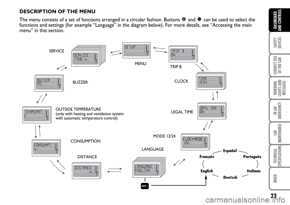
DESCRIPTION OF THE MENU
The menu consists of a set of functions arranged in a circular fashion. Buttons
âand ãcan be used to select the
functions and settings (for example “Language” in the diagram below). For more details, see “Accessing the main
menu” in this section.
MENU
TRIP B
CLOCK
LEGAL TIME
MODE 12/24
LANGUAGE
DISTANCE CONSUMPTION OUTSIDE TEMPERATURE
(only with heating and ventilation system
with automatic temperature control)BUZZER SERVICE
Q
Español
Deutsch
Português
Italiano
Français
English
Page 106 of 266
105
SAFETY
DEVICES
CORRECT USE
OF THE CAR
WARNING
LIGHTS AND
MESSAGES
IN AN
EMERGENCY
CAR
MAINTENANCE
TECHNICAL
SPECIFICATIONS
INDEX
DASHBOARD
AND CONTROLS
Wiring diagram:
1 Telephone MUTE
5 Telephone AF IN+
6 Telephone AF IN–
7 positive (+) key
8 positive (+) lights
9 positive (+30)
10 electronic ground.
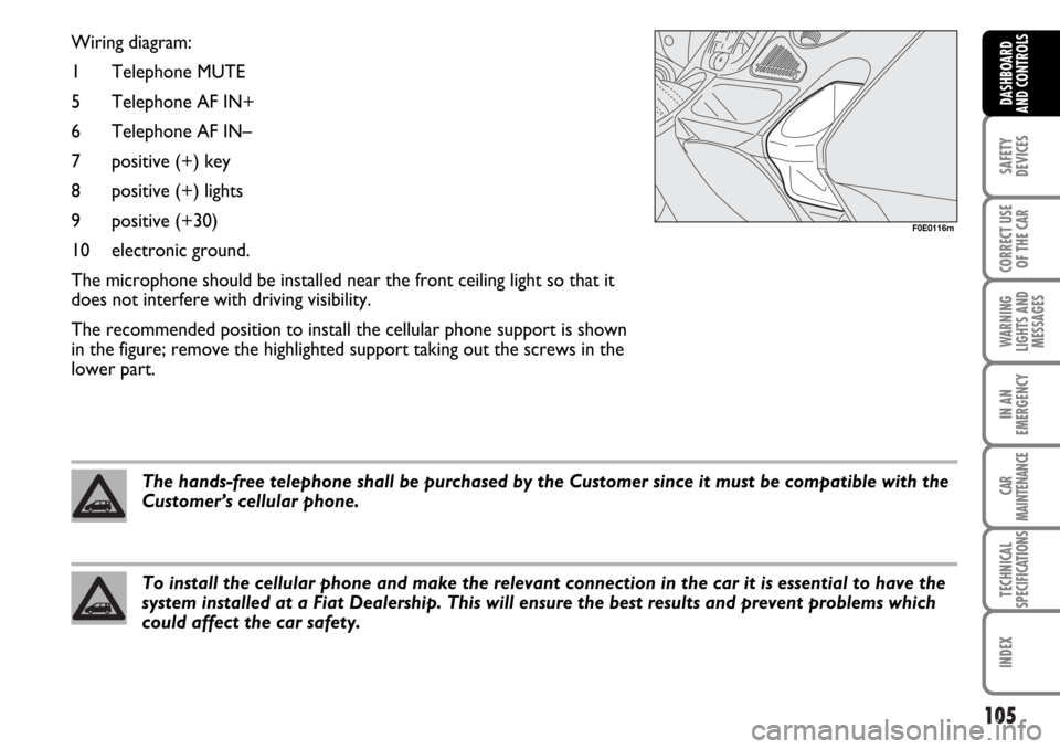
The microphone should be installed near the front ceiling light so that it
does not interfere with driving visibility.
The recommended position to install the cellular phone support is shown
in the figure; remove the highlighted support taking out the screws in the
lower part.
F0E0116m
The hands-free telephone shall be purchased by the Customer since it must be compatible with the
Customer’s cellular phone.
To install the cellular phone and make the relevant connection in the car it is essential to have the
system installed at a Fiat Dealership. This will ensure the best results and prevent problems which
could affect the car safety.
Page 143 of 266
142
WARNING
LIGHTS AND
MESSAGES
IN AN
EMERGENCY
CAR
MAINTENANCE
TECHNICAL
SPECIFICATIONS
INDEX
DASHBOARD
AND CONTROLS
SAFETY
DEVICES
CORRECT USE
OF THE CAR
USING THE MANUAL GEARBOX
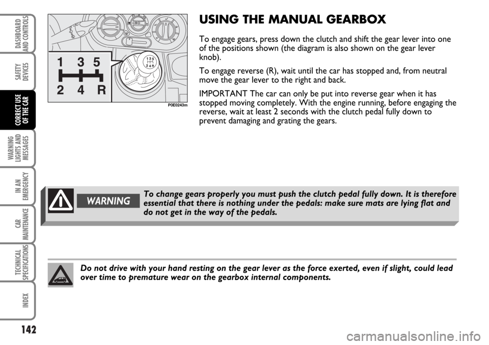
To engage gears, press down the clutch and shift the gear lever into one
of the positions shown (the diagram is also shown on the gear lever
knob).
To engage reverse (R), wait until the car has stopped and, from neutral
move the gear lever to the right and back.
IMPORTANT The car can only be put into reverse gear when it has
stopped moving completely. With the engine running, before engaging the
reverse, wait at least 2 seconds with the clutch pedal fully down to
prevent damaging and grating the gears.
P0E0243m
Do not drive with your hand resting on the gear lever as the force exerted, even if slight, could lead
over time to premature wear on the gearbox internal components.
To change gears properly you must push the clutch pedal fully down. It is therefore
essential that there is nothing under the pedals: make sure mats are lying flat and
do not get in the way of the pedals.WARNING
Page 148 of 266
147
WARNING
LIGHTS AND
MESSAGES
IN AN
EMERGENCY
CAR
MAINTENANCE
TECHNICAL
SPECIFICATIONS
INDEX
DASHBOARD
AND CONTROLS
SAFETY
DEVICES
CORRECT USE
OF THE CAR
F0E0192m
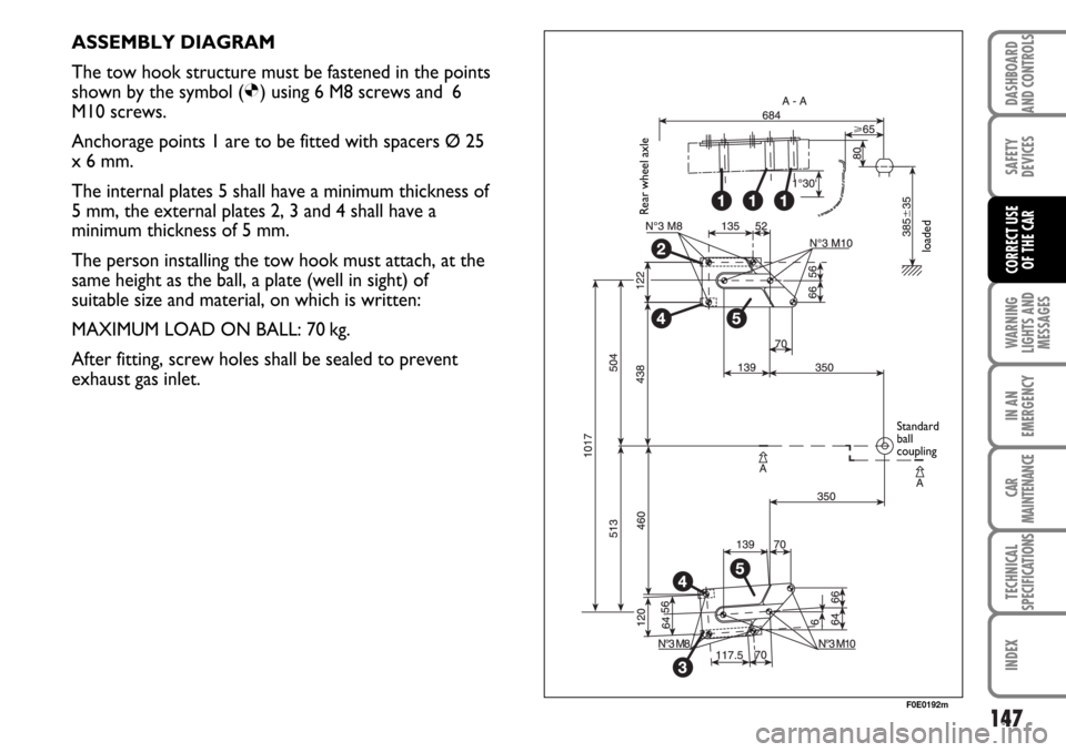
ASSEMBLY DIAGRAM
The tow hook structure must be fastened in the points
shown by the symbol (
Ø) using 6 M8 screws and 6
M10 screws.
Anchorage points 1 are to be fitted with spacers Ø 25
x 6 mm.
The internal plates 5 shall have a minimum thickness of
5 mm, the external plates 2, 3 and 4 shall have a
minimum thickness of 5 mm.
The person installing the tow hook must attach, at the
same height as the ball, a plate (well in sight) of
suitable size and material, on which is written:
MAXIMUM LOAD ON BALL: 70 kg.
After fitting, screw holes shall be sealed to prevent
exhaust gas inlet.
Rear wheel axle
loaded
Standard
ball
coupling
Page 149 of 266
148
WARNING
LIGHTS AND
MESSAGES
IN AN
EMERGENCY
CAR
MAINTENANCE
TECHNICAL
SPECIFICATIONS
INDEX
DASHBOARD
AND CONTROLS
SAFETY
DEVICES
CORRECT USE
OF THE CAR
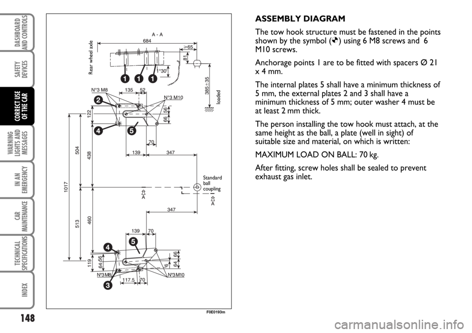
ASSEMBLY DIAGRAM
The tow hook structure must be fastened in the points
shown by the symbol (
Ø) using 6 M8 screws and 6
M10 screws.
Anchorage points 1 are to be fitted with spacers Ø 21
x 4 mm.
The internal plates 5 shall have a minimum thickness of
5 mm, the external plates 2 and 3 shall have a
minimum thickness of 5 mm; outer washer 4 must be
at least 2 mm thick.
The person installing the tow hook must attach, at the
same height as the ball, a plate (well in sight) of
suitable size and material, on which is written:
MAXIMUM LOAD ON BALL: 70 kg.
After fitting, screw holes shall be sealed to prevent
exhaust gas inlet.
F0E0193m
Rear wheel axle
loaded
Standard
ball
coupling
Page 261 of 266
TECHNICAL
SPECIFICATIONS
260
SAFETY
DEVICES
CORRECT USE
OF THE CAR
WARNING
LIGHTS AND
MESSAGES
CAR
MAINTENANCE
INDEXDASHBOARD
AND CONTROLS
IN AN
EMERGENCY
Steering wheel (adjustment) ......... 45
Storing the car ................................ 151
Sun visors .......................................... 70
Suspensions....................................... 239
Symbols.............................................. 6
Tachometer..................................... 18
Tank cap ............................................ 108
Third brake light .............................. 191
Top speeds ....................................... 246
Towing trailers
– important notes......................... 145
– installing the tow hook ............ 146
– assembly diagram ...................... 147
Towing the car ................................. 203
Tyre pressure................................... 243
Tyres
– changing a wheel ....................... 167
– geometry ..................................... 241
– important notes......................... 224
– inflation pressure....................... 243
– quick tyre repair kit
(FIX & GO automatic) ............. 177
– space-saver spare wheel.......... 242
– size and specification ................ 240
– understanding rim marking ..... 242
– understanding tyre marking .... 240
VAN (setup).................................... 99
Ventilation ......................................... 51
Weights ........................................... 247
Wheel geometry (toe-in) .............. 240
Wheel rims ...................................... 240
Wheels............................................... 240
Window cleaning
– windscreen washer (control) .. 61
– rear window washer (control) 62
– windscreen wiper (control).... 61
– rear window wiper (control) ... 62
Windows (cleaning) ........................ 231
Windscreen washer
– control ......................................... 61
– fluid level ..................................... 217
Windscreen wiper
– blades ........................................... 227
– control ......................................... 61
– nozzles ......................................... 228
Windscreen/rear window
wiper blades ................................... 226