FIAT PALIO 2003 178 / 1.G India Version Owners Manual
Manufacturer: FIAT, Model Year: 2003, Model line: PALIO, Model: FIAT PALIO 2003 178 / 1.GPages: 156, PDF Size: 6.27 MB
Page 131 of 156
130
ENGINES CODE -
BODYWORK VERSIONS
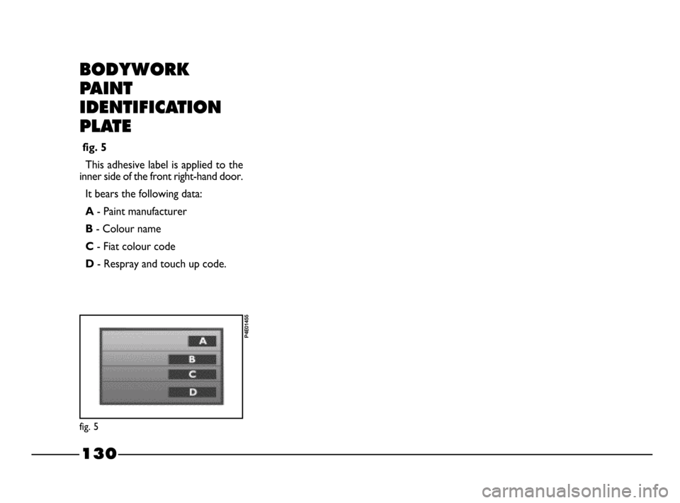
fig. 5
P4E01455
BODYWORK
PAINT
IDENTIFICATION
PLATE
fig. 5
This adhesive label is applied to the
inner side of the front right-hand door.
It bears the following data:
A - Paint manufacturer
B - Colour name
C - Fiat colour code
D- Respray and touch up code.
128-143 03/03/2003 07:39 PM Page 130
Page 132 of 156
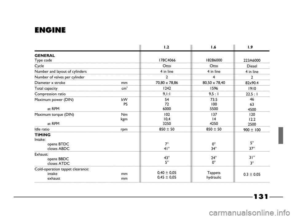
178C4066 182B6000
Otto Otto
4 in line 4 in line
24
70,80 x 78,86 80,50 x 78,40
1242 1596
9,1:1 9,5 : 1
54 73.5
72 100
6000 5500
102 137
10,4 14
3250 4250
850 ± 50 850 ± 50
7° 0°
41° 34°
43° 24°
5° 0°
0,40 ± 0,05 Tappets
0,45 ± 0,05 hydraulic
131
1.2 1.6 1.9
ENGINE
223A6000
Diesel
4 in line
2
82x90.4
1910
22.5 : 1
46
63
4500
120
12.2
2500
900 ± 100
5°
37°
31°
3°
0.3 ± 0.05
GENERAL
Type code
Cycle
Number and layout of cylinders
Number of valves per cylinder
Diameter x stroke mm
Total capacity cm3
Compression ratio
Maximum power (DIN) kW
PS
at RPM
Maximum torque (DIN) Nm
kgm
at RPM
Idle ratio rpm
TIMING
Intake:
opens BTDC
closes ABDC
Exhaust:
opens BBDC
closes ATDC
Cold-operation tappet clearance:
intake mm
exhaust mm
128-143 03/03/2003 07:39 PM Page 131
Page 133 of 156
132
FUEL SUPPLY/ IGNITION
Integrated multipoint electronic in-
jection and ignition system: only one
electronic control unit controls both
functions. It processes both the time
the injection lasts (for petrol meter-
ing) and the ignition advance angle.
Type: Multipoint.
Air cleaner: dry, with paper filtering
element.
Fuel pump: by immersion, in the tank.
Injection pressure 3 barMixture metered by electronic pro-
cessing of the data picked up by the
engine speed sensor and absolute
pressure sensor in the intake manifold.
Petrol metering system : a “Closed
Loop” (information on the combus-
tion trend transmitted by the sensor
Lambda).
Ignition order: 1-3-4-2.
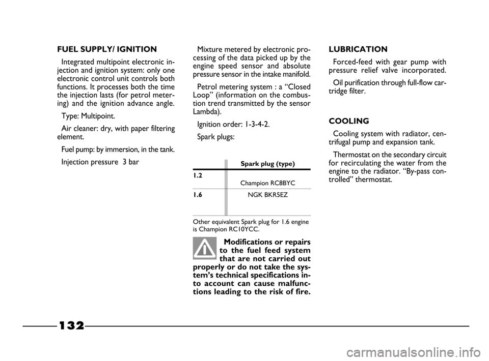
Spark plugs:
Modifications or repairs
to the fuel feed system
that are not carried out
properly or do not take the sys-
tem’s technical specifications in-
to account can cause malfunc-
tions leading to the risk of fire.
LUBRICATION
Forced-feed with gear pump with
pressure relief valve incorporated.
Oil purification through full-flow car-
tridge filter.
COOLING
Cooling system with radiator, cen-
trifugal pump and expansion tank.
Thermostat on the secondary circuit
for recirculating the water from the
engine to the radiator. “By-pass con-
trolled” thermostat.
Electrical fan for cooling the radiator
with connection/disconnection, con-
trolled by a thermostatic switch lo-
cated on the radiator.
Spark plug (type)
1.2
Champion RC7BMCChampion RC8BYC
1.6NGK BKR5EZ
Champion RC10YCC
Bosch FR8DE
Other equivalent Spark plug for 1.6 engine
is Champion RC10YCC.
128-143 03/03/2003 07:39 PM Page 132
Page 134 of 156
133
TRANSMISSION
CLUTCH
Self-adjusting with travel-free pedal.
Hydraulic clutch control.Cyclical gear reduction and differen-
tial assembly incorporated in the gear-
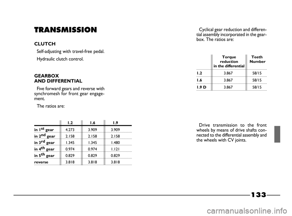
box. The ratios are:
Drive transmission to the front
wheels by means of drive shafts con-
nected to the differential assembly and
the wheels with CV joints.
GEARBOX
AND DIFFERENTIAL
Five forward gears and reverse with
synchromesh for front gear engage-
ment.
The ratios are:
1.2 1.6 1.9
in 1st
gear4.273 3.909 3.909
in 2nd
gear 2.158 2.158 2.158
in 3rd
gear 1.345 1.345 1.480
in 4th
gear0.974 0.974 1.121
in 5th
gear 0.829 0.829 0.829
reverse3.818 3.818 3.818
Torque Teeth
reduction Number
in the differential
1.23.867 58/15
1.63.867 58/15
1.9 D3.867 58/15
128-143 03/03/2003 07:39 PM Page 133
Page 135 of 156
134
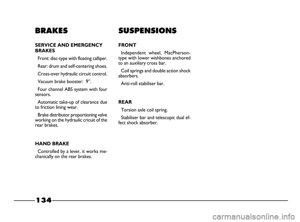
SUSPENSIONS
FRONT
Independent wheel, MacPherson-
type with lower wishbones anchored
to an auxiliary cross bar.
Coil springs and double action shock
absorbers.
Anti-roll stabiliser bar.
REAR
Torsion axle coil spring.
Stabiliser bar and telescopic dual ef-
fect shock absorber.
BRAKES
SERVICE AND EMERGENCY
BRAKES
Front: disc-type with floating calliper.
Rear: drum and self-centering shoes.
Cross-over hydraulic circuit control.
Vacuum brake booster: 9”.
Four channel ABS system with four
sensors.
Automatic take-up of clearance due
to friction lining wear.
Brake distributor proportioning valve
working on the hydraulic cricuit of the
rear brakes.
HAND BRAKE
Controlled by a lever, it works me-
chanically on the rear brakes.
128-143 03/03/2003 07:39 PM Page 134
Page 136 of 156
135
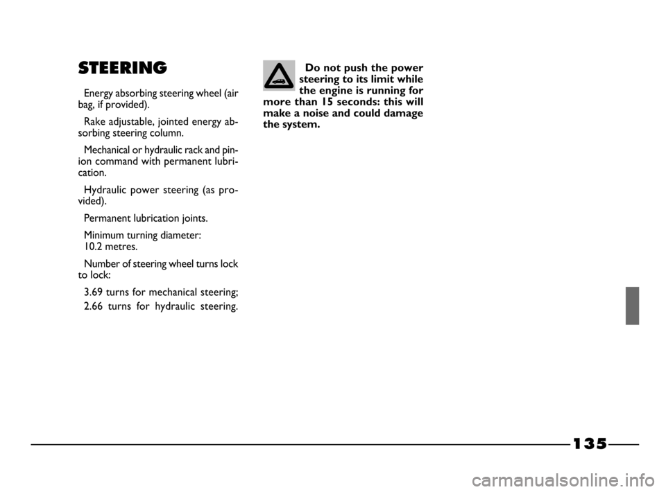
STEERING
Energy absorbing steering wheel (air
bag, if provided).
Rake adjustable, jointed energy ab-
sorbing steering column.
Mechanical or hydraulic rack and pin-
ion command with permanent lubri-
cation.
Hydraulic power steering (as pro-
vided).
Permanent lubrication joints.
Minimum turning diameter:
10.2 metres.
Number of steering wheel turns lock
to lock:
3.69 turns for mechanical steering;
2.66 turns for hydraulic steering.
Do not push the power
steering to its limit while
the engine is running for
more than 15 seconds: this will
make a noise and could damage
the system.
128-143 03/03/2003 07:39 PM Page 135
Page 137 of 156
136
Max speed index
Q
= up to 160 km/h.
R= up to 170 km/h.
S= up to 180 km/h.
T= up to 190 km/h.
U= up to 200 km/h.
H= up to 210 km/h.
V= up to 240 km/h.
W= up to 270 km/h.
Y= up to 300 km/h.
Load index (capacity)
60
= 250 kg
61 = 257 kg
62= 265 kg
63= 272 kg
64= 280 kg
65= 290 kg
66= 300 kg
67= 307 kg
68= 315 kg
69= 325 kg
70 = 335 kg
71= 345 kg
72= 355 kg
73= 365 kg
74= 375 kg
75= 387 kg
76= 400 kg
77= 412 kg
78= 425 kg
79= 437 kg
80= 450 kg
81= 462 kg
82= 475 kg
83= 487 kg
84= 500 kg
85= 515 kg
86= 530 kg
87= 545 kg
88= 560 kg
89= 580 kg
90= 600 kg
91= 615 kg
92= 630 kg
93= 650 kg
94= 670 kg
95= 690 kg
96 = 710 kg
97= 730 kg
98= 750 kg
99= 775 kg
100= 800 kg
101= 825 kg
102= 850 kg
103= 875 kg
104= 900 kg
1CORRECT READING
OF THE RIM fig. 6
The indications, necessary to know
the meaning of the identification ini-
tials printed on the rim, are listed be-
low.
CORRECT READING
OF THE TYRE fig. 6
The indications, necessary to know
the meaning of the identification ini-
tials printed on the tyre, are listed be-
low.
175= Nominal (S, distance in mm
between the sides).
65= height/width ratio (H/S) in per-
centage.
R= Radial tyre.
14= Diameter of the rim in inches
(Ø).
82= Load index (capacity).
T= Max speed index. Example
175/65 R 14 82 S
IMPORTANTThe light alloy
wheels are fixed with specific bolt in-
compatible with any printed steel
wheels, excluding the specific spare
wheel.
SNOW TYRES
Use reduced dimension winter tyres,
see “Snow Chains” chapter.
WHEEL GEOMETRY
Convergence of the front wheel mea-
sured between the rims: –1±1(Power
Steering), +1mm (Mechnical Steering).
The values refer to a car after running in.
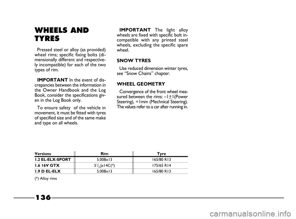
WHEELS AND
TYRES
Pressed steel or alloy (as provided)
wheel rims; specific fixing bolts (di-
mensionally different and respective-
ly incompatible) for each of the two
types of rim.
IMPORTANTIn the event of dis-
crepancies between the information in
the Owner Handbook and the Log
Book, consider the specifications giv-
en in the Log Book only.
To ensure safety of the vehicle in
movement, it must be fitted with tyres
of specified size and of the same make
and type on all wheels.
Versions Rim Tyre
1.2 EL-ELX-SPORT5.00Bx13 165/80 R13
1.6 16V GTX51/2 Jx14C(*) 175/65 R14
1.9 D EL-ELX5.00Bx13 165/80 R13
(*) Alloy rims
128-143 03/03/2003 07:39 PM Page 136
Page 138 of 156
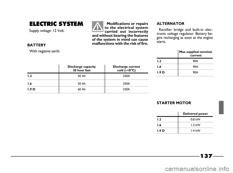
Delivered power
1.20.8 kW
1.61.3 kW
1.9 D1.4 kW
137
ALTERNATOR
Rectifier bridge and built-in elec-
tronic voltage regulator. Battery be-
gins recharging as soon as the engine
starts.
STARTER MOTOR Modifications or repairs
to the electrical system
carried out incorrectly
and without bearing the features
of the system in mind can cause
malfunctions with the risk of fire.
ELECTRIC SYSTEM
Supply voltage: 12 Volt.
BATTERY
With negative earth.
Discharge capacity Discharge current 20 hour fast cold (–18°C)
1.250 Ah 250A
1.650 Ah 250A
1.9 D60 Ah 320A
Max supplied nominalcurrent
1.290A
1.690A
1.9 D90A
128-143 03/03/2003 07:39 PM Page 137
Page 139 of 156
1015 1085
375 375
800 850
800 800
50 50
138
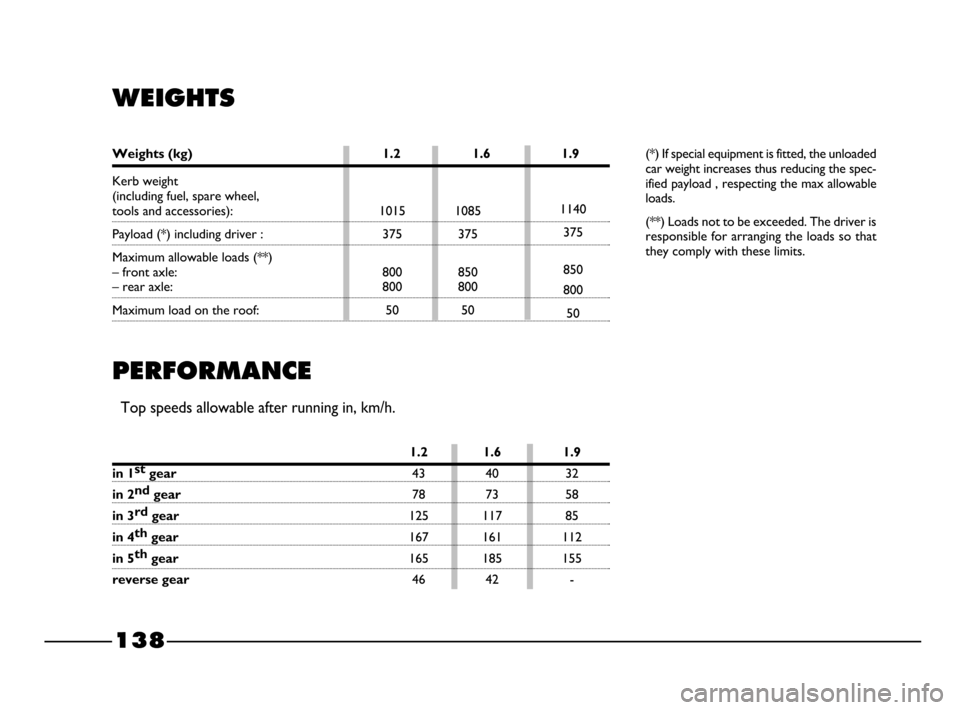
WEIGHTS
(*) If special equipment is fitted, the unloaded
car weight increases thus reducing the spec-
ified payload , respecting the max allowable
loads.
(**) Loads not to be exceeded. The driver is
responsible for arranging the loads so that
they comply with these limits.
PERFORMANCE
Top speeds allowable after running in, km/h.
1140
375
850
800
50 Kerb weight
(including fuel, spare wheel, tools and accessories):
Payload (*) including driver :
Maximum allowable loads (**)
– front axle:
– rear axle:
Maximum load on the roof:
Weights (kg) 1.2 1.6 1.9
1.2 1.6 1.9
in 1st
gear43 40 32
in 2nd
gear78 73 58
in 3rd
gear125 117 85
in 4th
gear167 161 112
in 5th
gear165 185 155
reverse gear46 42 -
128-143 03/03/2003 07:39 PM Page 138
Page 140 of 156
139
P4E02266
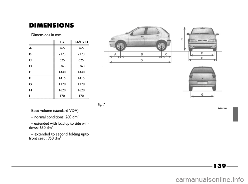
DIMENSIONS
Dimensions in mm.
1.2 1.6/1.9 D
A765 765
B2373 2373
C625 625
D3763 3763
E1440 1440
F1415 1415
G1378 1378
H1620 1620
Boot volume (standard VDA):
– normal conditions: 260 dm
3
– extended with load up to side win-
dows: 650 dm3
– extended to second folding upto
front seat : 950 dm3
fig. 7
I170 170
128-143 03/03/2003 07:39 PM Page 139