wheel bolts FIAT PALIO 2003 178 / 1.G India Version Owners Manual
[x] Cancel search | Manufacturer: FIAT, Model Year: 2003, Model line: PALIO, Model: FIAT PALIO 2003 178 / 1.GPages: 156, PDF Size: 6.27 MB
Page 83 of 156

82
BUMP STARTING IF A TYRE IS
PUNCTURED
Follow the instructions on this and
the following pages to use the jack and
spare wheel correctly.
Remember that until
the engine has started the
brake booster and power
steering systems will not work
and a greater effort will therefore
be required to depress the brake
pedal or turn the steering wheel.
An incorrectly posi-
tioned jack may cause the
car to fall.
Do not use the jack to lift loads
exceeding that indicated on the
label attached to the jack itself.
The jack should only be used to
change a wheel on the car for
which it is designed. It should not
be put to other uses or employed
to raise other models of cars. Un-
der no circumstances should it be
used when carrying out repairs
under the car.
Do not lubricate the bolt
threads before fitting them back:
they could come loose.
Never start the engine,
when the car is raised on
a jack. Never tamper with
the inflation valve. Never place
tools between the rim and tyre.
Check the tyre and spare wheel
pressure regularly. The tyre in-
flation pressure is shown in the
“Technical specifications” chap-
ter.
Never bump start the
engine (by pushing, tow-
ing or coasting downhill).
This could cause fuel to flow in-
to the catalytic exhaust system
and damage it beyond repair.
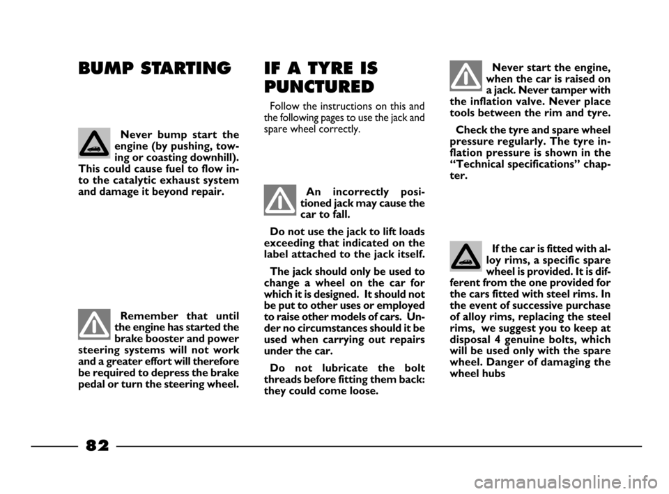
If the car is fitted with al-
loy rims, a specific spare
wheel is provided. It is dif-
ferent from the one provided for
the cars fitted with steel rims. In
the event of successive purchase
of alloy rims, replacing the steel
rims, we suggest you to keep at
disposal 4 genuine bolts, which
will be used only with the spare
wheel. Danger of damaging the
wheel hubs
80-103 03/03/2003 06:49 PM Page 82
Page 85 of 156

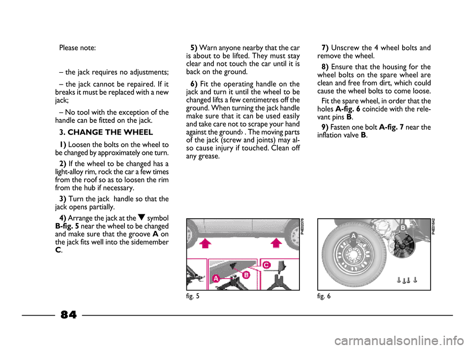
5) Warn anyone nearby that the car
is about to be lifted. They must stay
clear and not touch the car until it is
back on the ground.
6)Fit the operating handle on the
jack and turn it until the wheel to be
changed lifts a few centimetres off the
ground. When turning the jack handle
make sure that it can be used easily
and take care not to scrape your hand
against the ground› . The moving parts
of the jack (screw and joints) may al-
so cause injury if touched. Clean off
any grease.
7)Unscrew the 4 wheel bolts and
remove the wheel.
8) Ensure that the housing for the
wheel bolts on the spare wheel are
clean and free from dirt, which could
cause the wheel bolts to come loose.
Fit the spare wheel, in order that the
holes
A-fig. 6coincide with the rele-
vant pins
B.
9) Fasten one bolt A-fig. 7near the
inflation valve
B.
fig. 6
P4E01642
fig. 5
P4E02376
84
Please note:
– the jack weighs 2.900 kg;
– the jack requires no adjustments;
– the jack cannot be repaired. If it
breaks it must be replaced with a new
jack;
– No tool with the exception of the
handle can be fitted on the jack.
3. CHANGE THE WHEEL
1)
Loosen the bolts on the wheel to
be changed by approximately one turn.
2) If the wheel to be changed has a
light-alloy rim, rock the car a few times
from the roof so as to loosen the rim
from the hub if necessary.
3) Turn the jack handle so that the
jack opens partially.
4)Arrange the jack at the Osymbol
B-fig. 5 near the wheel to be changed
and make sure that the groove
Aon
the jack fits well into the sidemember
C.
80-103 03/03/2003 06:49 PM Page 84
Page 86 of 156

85
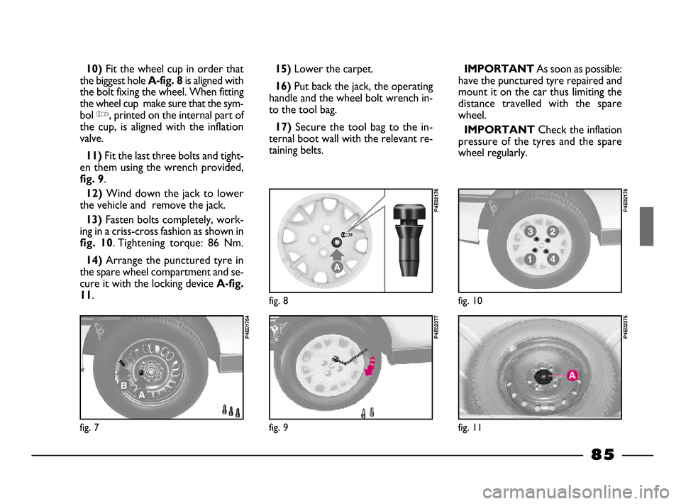
10)Fit the wheel cup in order that
the biggest hole
A-fig. 8is aligned with
the bolt fixing the wheel. When fitting
the wheel cup make sure that the sym-
bol
Y, printed on the internal part of
the cup, is aligned with the inflation
valve.
11)Fit the last three bolts and tight-
en them using the wrench provided,
fig. 9.
12)Wind down the jack to lower
the vehicle and remove the jack.
13)Fasten bolts completely, work-
ing in a criss-cross fashion as shown in
fig. 10. Tightening torque: 86 Nm.
14)Arrange the punctured tyre in
the spare wheel compartment and se-
cure it with the locking device
A-fig.
11
.
fig. 7
P4E01754
15)Lower the carpet.
16)Put back the jack, the operating
handle and the wheel bolt wrench in-
to the tool bag.
17)Secure the tool bag to the in-
ternal boot wall with the relevant re-
taining belts.
fig. 8
P4E02176
fig. 9
P4E02377
IMPORTANT As soon as possible:
have the punctured tyre repaired and
mount it on the car thus limiting the
distance travelled with the spare
wheel.
IMPORTANT Check the inflation
pressure of the tyres and the spare
wheel regularly.
fig. 10
P4E02178
fig. 11
P4E02375
80-103 03/03/2003 06:49 PM Page 85
Page 137 of 156

136
Max speed index
Q
= up to 160 km/h.
R= up to 170 km/h.
S= up to 180 km/h.
T= up to 190 km/h.
U= up to 200 km/h.
H= up to 210 km/h.
V= up to 240 km/h.
W= up to 270 km/h.
Y= up to 300 km/h.
Load index (capacity)
60
= 250 kg
61 = 257 kg
62= 265 kg
63= 272 kg
64= 280 kg
65= 290 kg
66= 300 kg
67= 307 kg
68= 315 kg
69= 325 kg
70 = 335 kg
71= 345 kg
72= 355 kg
73= 365 kg
74= 375 kg
75= 387 kg
76= 400 kg
77= 412 kg
78= 425 kg
79= 437 kg
80= 450 kg
81= 462 kg
82= 475 kg
83= 487 kg
84= 500 kg
85= 515 kg
86= 530 kg
87= 545 kg
88= 560 kg
89= 580 kg
90= 600 kg
91= 615 kg
92= 630 kg
93= 650 kg
94= 670 kg
95= 690 kg
96 = 710 kg
97= 730 kg
98= 750 kg
99= 775 kg
100= 800 kg
101= 825 kg
102= 850 kg
103= 875 kg
104= 900 kg
1CORRECT READING
OF THE RIM fig. 6
The indications, necessary to know
the meaning of the identification ini-
tials printed on the rim, are listed be-
low.
CORRECT READING
OF THE TYRE fig. 6
The indications, necessary to know
the meaning of the identification ini-
tials printed on the tyre, are listed be-
low.
175= Nominal (S, distance in mm
between the sides).
65= height/width ratio (H/S) in per-
centage.
R= Radial tyre.
14= Diameter of the rim in inches
(Ø).
82= Load index (capacity).
T= Max speed index. Example
175/65 R 14 82 S
IMPORTANTThe light alloy
wheels are fixed with specific bolt in-
compatible with any printed steel
wheels, excluding the specific spare
wheel.
SNOW TYRES
Use reduced dimension winter tyres,
see “Snow Chains” chapter.
WHEEL GEOMETRY
Convergence of the front wheel mea-
sured between the rims: –1±1(Power
Steering), +1mm (Mechnical Steering).
The values refer to a car after running in.
WHEELS AND
TYRES
Pressed steel or alloy (as provided)
wheel rims; specific fixing bolts (di-
mensionally different and respective-
ly incompatible) for each of the two
types of rim.
IMPORTANTIn the event of dis-
crepancies between the information in
the Owner Handbook and the Log
Book, consider the specifications giv-
en in the Log Book only.
To ensure safety of the vehicle in
movement, it must be fitted with tyres
of specified size and of the same make
and type on all wheels.
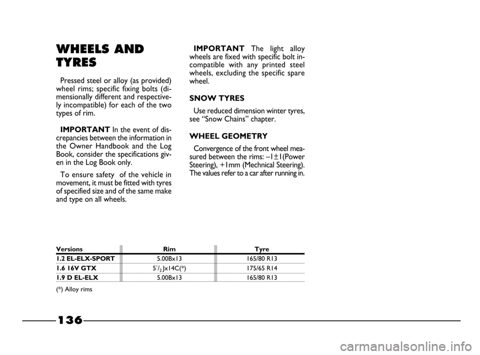
Versions Rim Tyre
1.2 EL-ELX-SPORT5.00Bx13 165/80 R13
1.6 16V GTX51/2 Jx14C(*) 175/65 R14
1.9 D EL-ELX5.00Bx13 165/80 R13
(*) Alloy rims
128-143 03/03/2003 07:39 PM Page 136