Speed FIAT PUNTO 1994 176 / 1.G User Guide
[x] Cancel search | Manufacturer: FIAT, Model Year: 1994, Model line: PUNTO, Model: FIAT PUNTO 1994 176 / 1.GPages: 225, PDF Size: 18.54 MB
Page 38 of 225
1B.2
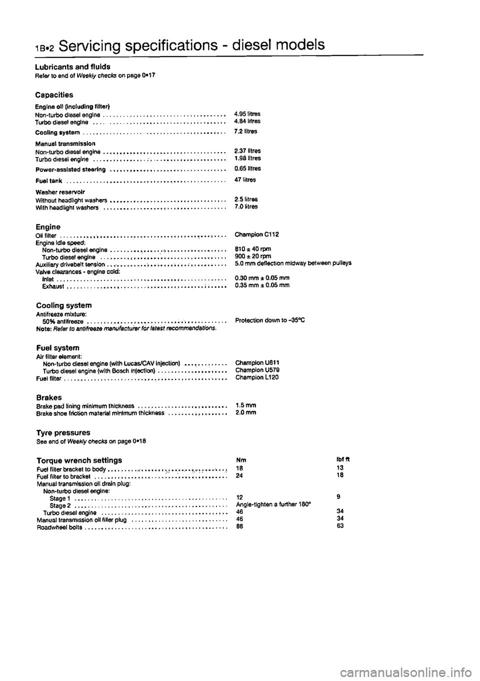
Servicing specifications - diesel models
Lubricants and fluids Refer to end of Weekly checks on page 0*17
Capacities Engine oil (including filter) Non-turbo diesei engine 4.95 litres Turbo diesel engine 4.84 litres Cooling system 7.2 litres
Manual transmission Non-turbo diesel engine 2.37 litres Turbo diesei engine t .98 litres Power-assisted steering 0.65 litres
Fuel tank 47 litres Washer reservoir Without headlight washers 2.5 litres With headlight washers 7.0 litres
Engine Oil fitter Engine Idle speed: Non-turbo diesel engine Turbo diesel engine Auxiliary drivebelt tension ...... Valve clearances • engine cold: Inlet Exhaust
Champion C112
8l0«40rpm 900 ± 20 rpm 5.0 mm deflection midway between pulleys
0.30 mm * 0.05 mm 0.35 mm ± 0.05 mm
Cooling system Antifreeze mixture: 50% antifreeze Protection down to-35°C Note: Refer to antifreeze manufactuivr for latest recommendations.
Fuel system Air filter element: Non-turbo diesel engine (with Lucas/CAV Injection) Champion U611 Turbo diesel engine (with Bosch Injection) Champion U579 Fuel filter Champion L120
Brakes Brake pad lining minimum thickness 1-5 mm Brake shoe friction material minimum thickness 2.0 mm
Tyre pressures See end of Weekly checks on page 0*18
Torque wrench settings Fuel filter bracket to body ..... « Fuel filter to bracket i........ Manual transmission oil drain plug: Non-turbo diesel engine: Stage 1 Stage 2 Turbo diesel engine Manual transmission oil filler plug Roadwheel bolts
Nm Ibfft 18 13 24 18
12 9 Angle-tighten a further 180® 46 34 46 34
Page 39 of 225
Maintenance schedule - diesel models 1B.3
The mamtenance intervals in this manual are provided with the assumption that you. reI ihe dealer, will be carrying out the work.
These
are the minimum maintenance intervals recommended by us for vehicles driven daily.
ff you wish to keep your vehicle In peak condition at all times, you may wish to perform some of these procedures more often. We encourage frequent maintenance, because it enhances the efficiency.
performance and resale value of your vehicle. When the vehicle Is new, it should be serviced by a factory-authorised dealer service department, in order to preserve the factory warranty.
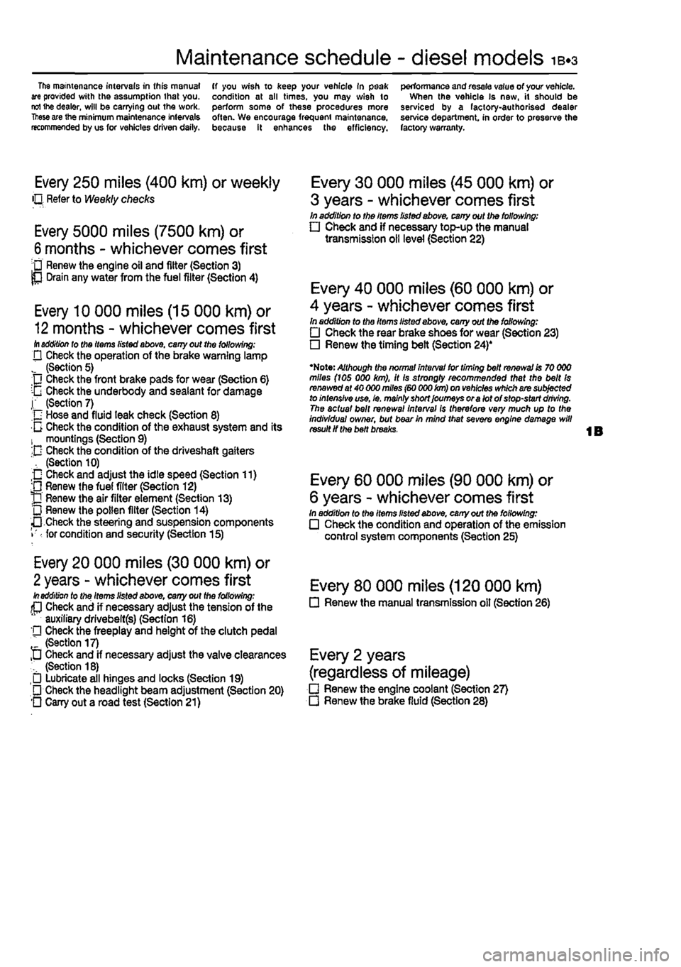
Every 250 miles (400 km) or weekly O Refer to Weekly checks
Every 5000 miles (7500 km) or
6
months - whichever comes first • Renew the engine oil and filter (Section 3) P Drain any water from the fuel filter (Section 4)
Every 10 000 miles (15 000 km) or
12
months - whichever comes first ill addition lo tho Items listed above, cany out the following; D Check the operation of the brake warning lamp J (Section 5) Check the front brake pads for wear (Section 6) :-G Check the underbody and sealant for damage j" (Section 7) n Hose and fluid leak check (Section 8) 0 Check the condition of the exhaust system and its 1 mountings (Section 9) -D Check the condition of the driveshaft gaiters ", (Section 10) O Check and adjust the idle speed (Section 11) ;0 Renew (he fuel filter (Section 12) J] Renew the air filter element (Section 13) L) Renew the pollen filter (Section 14) •• Check the steering and suspension components • for condition and security (Section 15)
Every 20 000 miles (30 000 km) or
2
years - whichever comes first In addition to the Items listed above, cany out the following: (P Check and if necessary adjust the tension of the auxiliary drlvebeltfs) (Section 16) '• Check the freeplay and height of the clutch pedal " (Section 17) D Check and if necessary adjust the valve clearances (Section 18) Lubricate all hinges and locks (Section 19) • Check the headlight beam adjustment (Section 20) O Cany out a road test (Section 21)
Every 30 000 miles (45 000 km) or
3 years - whichever comes first In addition to the Items listed above, cany out the following: • Check and if necessary top-up the manual transmission oil level (Section 22)
Every 40 000 miles (60 000 km) or
4 years - whichever comes first In addition to the items listed above, cany out the following: • Check the rear brake shoes for wear (Section 23) • Renew the timing belt (Section 24)'
•Note: Although the normal interval for timing belt renewal is 70 000 miles (ids 000 km), it is strongly recommended that the belt Is renewed at 40 000 miles (60 000 km) on vehicles which are subjected to intensive use, le. mainly short Journeys or a lot of stop-start driving. The actual bait renewal interval Is therefore very much up to the Individual owner, but bear in mind that sevefe engine damage will result if the belt breaks.
Every 60 000 miles (90 000 km) or
6 years - whichever comes first In addition to the Items listed above, cany out the following: • Check the condition and operation of the emission control system components (Section 25)
Every 80 000 miles (120 000 km) • Renew the manual transmission oil (Section 26)
Every 2 years
(regardless of mileage) • Renew the engine coolant (Section 27) • Renew the brake fluid (Section 28)
Page 41 of 225
Component location - diesel models ib-s
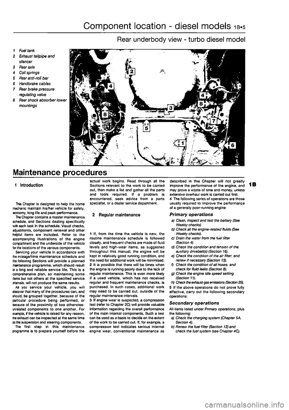
Rear underbody view - turbo diesel model
1
Fuel tank
2
Exhaust
tailpipe
and
silencer 3 Fear axle 4 Coil springs 5
Rear anti-roll bar
€
Handbrake cables
7
Rear brake pressure regulating valve
8
Rear shock
absorber
lower
mountings
Maintenance procedures
1 Introduction
This Chapter Is designed to help the home mechanic maintain his/her vehicle for safety, economy, long life and peak performance. The Chapter contains a master maintenance schedule, and Sections dealing specifically with each task in the schedule. Visual checks, adjustments, component renewal and other helpful items are included. Refer to the accompanying illustrations of the engine compartment and the underside of the vohicle for the locations of the various components. Servicing your vehicle in accordance with ihe mileage/time maintenance schedule and the following Sections will provide a planned maintenance programme, which should result in a long and reliable service life. This is a comprehensive plan, so maintaining some items but not others at the specified service internals, will not produce the same results. As you service your vehicle, you will ctecover that many of the procedures can. and should, be grouped together, because of the particular procedure being performed, or because of the proximity of two otherwise-unrelated components to one another. For example, if the vehicle is raised for any reason, the exhaust can be inspected at the same time as the suspension and steering components. The first step in this maintenance programme is to prepare yoursetf before the
actual work begins. Read through all the Sections relevant to the work to be carried out. then make a list and gather all the parts and tools required. If a problem is encountered, seek advice from a parts specialist, or a dealer service department.
2 Regular maintenance
1 If, from the time Ihe vehicle is new, the routine maintenance schedule is followed closely, and frequent checks are made of fluid levels and high-wear Items, as suggested throughout this manual, the engine wifl be kept in relatively good running condition, and the need for additional work will be minimised. 2 It is possible that there will be times when the engine is running poorly due to the lack of regular maintenance. This is even more likely if a used vehicle, which has not received regular and frequent maintenance checks, is purchased, in such cases, additions! work may need to be carried out, outside of the regular maintenance intervals. 3 If engine wear is suspected, a compression test {refer to Chapter 2C} will provide valuable information regarding the overall performance of the main internal components. Such a test can be used as a basis to decide on the extent of the work to be carried out. If, for example, a compression test indicates serious Internal engine wear, conventional maintenance as
described in this Chapter will not greatly improve the performance of the engine, and may prove a wa3te of time and money, unless extensive overhaul work Is carried out first. 4 The following series of operations are those usually required to Improve the performance of a generally poor-running engine:
Primary operations a,I Clean, Inspect and test the battery (See Weekly checks). b) Check all the engine-related fluids (See Weekly checks). c) Drain the water from the fuel filter (Section 4) d) Check the condition and tension of the auxiliary dnvebeft(s) (Section 16). e) Check the condition of the air fitter, and renew if necessary (Section 13). f) Check the condition of all hoses, and check for fluid leaks (Section 8). g) Check the engine idle speed setting {Section 11). h) Check the exhaust gas emissions (Section 25). 5 If the above operations do not prove fully effective, carry out the following secondary operations:
Secondary operations All items listed under Pnmary operations, plus the following: a) Check the charging system (Chapter 5A, Section 4). b) Renew the fuel filter (Section 12) and check the fuel system (see Chapter 4Q.
Page 44 of 225
ib-8 Every 10 000 miles - diesel models
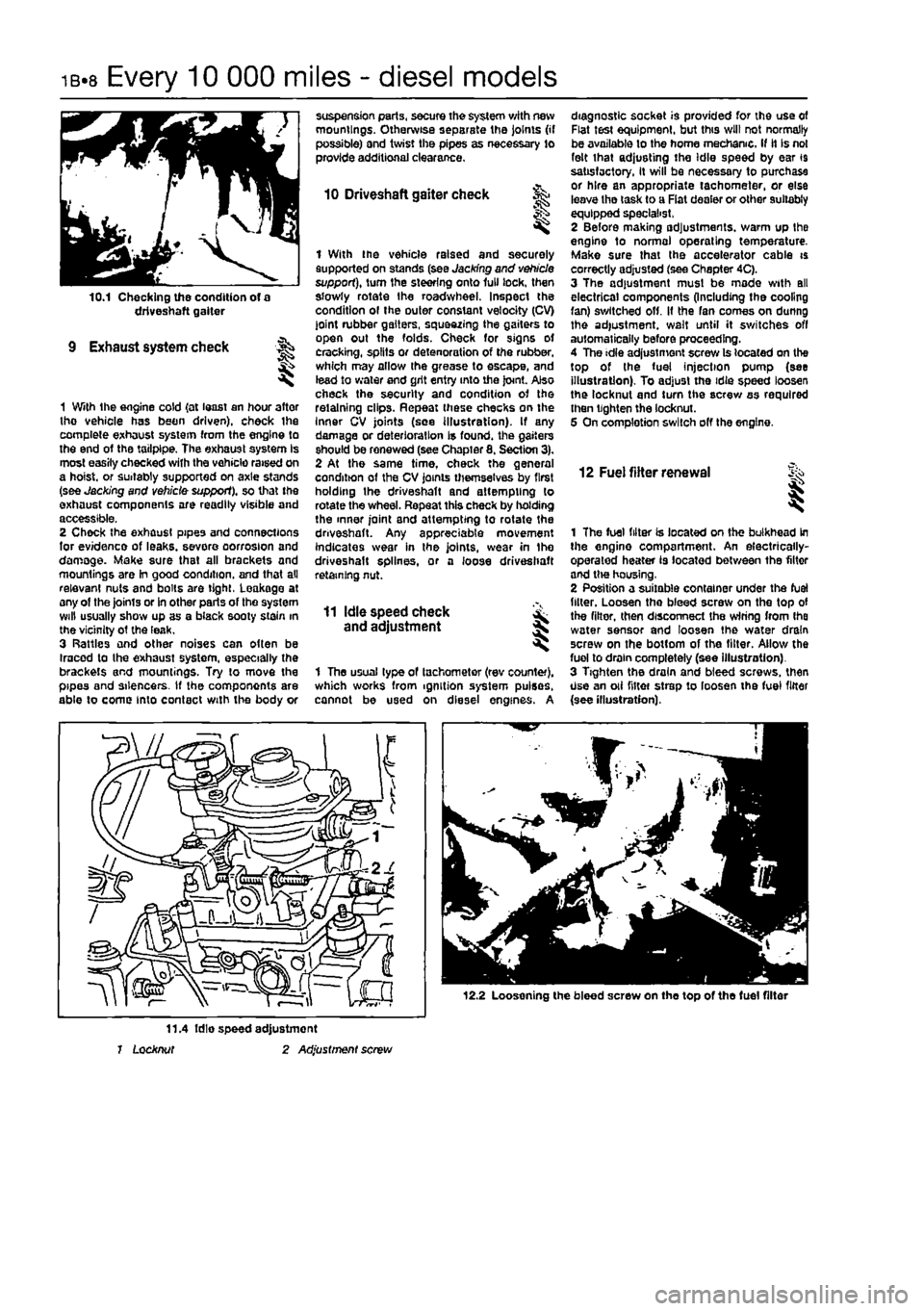
10.1 Checking the condition of a driveshaft gaiter
9 Exhaust system check
1 With the engine cold {at least an hour after tho vehicle has been driven), check ihe complete exhaust system from the engine to the end of the tailpipe. The exhaust system Is most easily checked with the vehicle raised on a hoist, or suitably supported on axle stands (see Jacking and vehicle support), so that the exhaust components are readily visible and accessible. 2 Check the exhaust pipes and connections for evidence of leaks, severe oorrosion and damage. Make sure that all brackets and mountings are In good condition, and that all relevant nuts and bolts are tight, Leakage at any of the joints or in other parts of tho system will usually show up as a black sooty stain in the vicinity ot the leak. 3 Rattles and other noises can often be Iracod to the exhaust system, especially the brackets and mountings. Try to move the pipes and silencers. If the components are able to come into contact with the body or
suspension parts, secure the system with new mountings. Otherwise separate the joints (if possible) and twist the pipes as necessary to provide additional clearance.
10 Driveshaft gaiter check
I
1 With the vehicle raised and securely supported on stands (see Jacking and vehicle support), turn the steering onto lull lock, then slowly rotate the roadwheel. Inspect the condition ol the outer constant velocity (CV) joint rubber gaiters, squeezing the gaiters to open out the folds. Check for signs ot cracking, splits or detenoration of the rubber, which may allow the grease to escape, and lead to water and grit entry into the joint. Also check the security and condition of the retaining clips. Repeat these checks on the Inner CV joints (see illustration). If any damage or deterioration is found, the gaiters should be renewed (see Chapter 8. Section 3). 2 At the same time, check the general condition of the CV joints themselves by first holding the driveshaft and attempting to rotate the wheel. Repeat this check by holding the inner joint and attempting to rotate the driveshaft. Any appreciable movement indicates wear in the joints, wear in Ihe driveshaft splines, or a loose driveshaft retaining nut.
11 Idle speed check and adjustment
1 The usual type of tachometer (rev counter), which works from ignition system pulses, cannot be used on diesel engines. A
diagnostic socket is provided for the use of Flat test equipment, but this will not normally be available to the home mechanic. If it Is not felt that adjusting the Idle speed by ear 19 satisfactory, It will be necessary to purchase or hire an appropriate tachometer, or else leave tho task to a Fiat dealer or other suitably equipped specialist, 2 Before making adjustments, warm up the engine to normal operating temperature. Make sure that the accelerator cable is correctly adjusted (see Chapter 4C). 3 The adjustment must be made with all electrical components (Including the cooling fan) switched off. It the fan comes on dunng the adjustment, wait until it switches off automatically before proceeding. 4 The idle adjustment screw Is located on the top of the fuel injection pump (see illustration). To adjust the idie speed loosen the locknut and turn the screw as required then tighten the locknut. 5 On completion switch off the engine.
12 Fuel filter renewal i
1 The fuel filter is located on the bulkhead in the engine compartment. An electrically-operated heater is located between the filter and tlw housing, 2 Position a suitable container under the fuel filler. Loosen tho bleed screw on the top of the filter, then disconnect the wiring from Ihe water sensor and loosen the water drain screw on the bottom of the filter. Allow the fuel to drain completely (see illustration). 3 Tighten the drain and bleed screws, then Use an oii niter strep to loosen the fuel filter {see illustration).
12.2 Loosening the bleed screw on the top of the fuel filter
11.4 fdie speed adjustment 1 Locknut 2 Adjustment screw
Page 53 of 225
2A*10 SOHC (8-valve) petrol engine in-car repair procedures
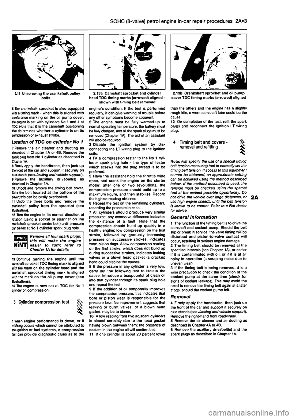
2.11 Unscrewing the crankshaft pulley bolts
6 Itae crankshaft sprocket Is also equipped •nth a timing mark - when this is aligned with 3relarence marking on the oil pump cover.
Hie
engine is set with cylinders No 1 and 4 at
TDC.
Note that it is the camshaft positioning that determines whether a cylinder is on its comcression or exhaust stroke.
Location
of TDC on cylinder No 1 7 Remove the air cleaner and ducting as descnbed in Chapter 4A or 4B. Remove the
spark
plug from No 1 cylinder as described in Chapter 1A. 8 Firmly apply the handbrake, then |ack up
the
front of the car and support it securely on iiia stands (see Jacking end vehicle support). 9 Remove the auxiliary drivebelt(s) as described in Chapter 1A. 10 Unbolt and remove the timing belt cover. Mole the bolt located at the bottom of the
coven
this can be easily overlooked. 11 Undo the three bolts and remove the crankshaft pulley from the sprocket (see {lustration). 12 Turn Ihe engine in its normal direction of rotation (using a socket or spanner on Ihe crankshaft sprocket centre bolt) until pressure an be felt at No
1
cylinder spark plug hole.
1 flfliyflg^ Remove all four spark plugs; "••"•1 this will make the engine HlNTl easier to turn; refer to Chapter 1A for details.
13 Continue turning the engine until the crahaft sprocket TDC timing mark is aligned with the mark on the cylinder head and the crankshaft sprocket timing mark is aligned with the mark on the oil pump cover (see ilustrations). 14 The engine is now set at TDC for No 1 cylinder on compression.
3 Cylinder compression test t ^
1 When engine performance Is down, or if misfiring occurs which cannot be attributed to tne ignition or fuei systems, a compression isst can provide diagnostic clues as to the
2.13a Camshaft sprocket and cylinder head TDC timing marks (arrowed) aligned -shown with timing belt removed engine's condition. II the test is performed regularly, it can give warning of trouble any other symptoms become apparent. 2 The engine must be fully warmed-up to normal operating temperature, the battery must be fufly charged, and all the spark plugs must be removed (Chapter 1A). The aid of an assistant will also be required. 3 Disable the ignition system by dis-connecting the LT wiring plug to the ignition coils. 4 Fit a compression tester to the No 1 cyl-inder spark plug hole - the type of tester which screws into the plug thread is to be preferred, 5 Have the assistant hold the throttle wide open, and crank the engine on the starter motor; after one or two revolutions, the compression pressure should build up to a maximum figure, and then stabilise. Record the highest reading obtained. 6 Repeat the lest on the remaining cylinders, recording the pressure in each. 7 All cylinders should produce very similar pressures; any excessive difference indicates the existence of a fault. Note that the compression should build up quickly in a healthy engine; low compression on the first stroke, followed by gradually increasing pressure on successive strokes, indicates worn piston rings. A low compression reading on the first stroke, which does not build up during successive strokes, indicates leaking valves or a blown head gasket (a cracked head could also be the cause). 8 If the pressure in any cylinder is very low. carry out the following test to isolate the cause. Introduce a teaspoonful of clean oil into that cylinder through its spark plug hole and repeat the test. 9 If the addition of oil temporarily improves the compression pressure, this indicates that bore or piston wear Is responsible for the pressure loss. No improvement suggests that leaking or burnt valves, or a biown head gasket, may be to blame. 10 A low reading from two adjacent cylinders is almost certainly due to the head gasket having blown between them; the presence of coolant in the engine oil will confirm this. 11 If one cylinder is about 20 percent lower
2.13b Crankshaft sprocket and oil pump cover TDC timing marks (arrowed) aligned
than the others and Ihe engine has a slightly rough idle, a worn camshaft lobe could be the cause. 12 On completion of the test, refit the spark plugs and reconnect the ignition LT wiring plug.
4 Timing belt and covers -removal and refitting ^
Note: Fiat specify the use of a special timing belt fens/on measuring toot to correctly set tho timing belt tension. If access to this equipment cannot be obtained, an approximate setting can be achieved using the method described below. It the method described is used, the tension must be checked using the special tool at the earliest possible opportunity. Do not drive the vehicle over large distances, or use high engine speeds, until the belt tension is known fo be correct. Refer to a Fiat dealer foradvSce.
General information 1 The function of the timing belt is to drive Ihe camshaft and coolant pump. Should the belt slip or break In service, the valve timing will be disturbed and piston-to-valvo contact will occur, resulting in serious engine damage, 2 The timing belt should be renewed ai the specified intervals (see Chapter 1A), or earlier if it is contaminated with oil. or if it is at all noisy in operation (a scraping noise due to uneven wear). 3 If the timing belt is being removed, it Is a wise precaution to check the condition of the coolant pump at the same time (check for signs of coolant leakage). This may avoid the need to remove the timing belt again at a later stage, should the coolant pump fall.
Removal 4 Firmly apply the handbrake, then jack up the front of the car and support it securely on axle stands (see Jacking and vehicle support). Remove the right-hand front road wheel. 5 Remove the air cleaner and air ducting as described in Chapter 4A or 46. 6 Remove the auxiliary drivebelt(s) and the spark plugs as described in Chapter 1A.
2A
Page 76 of 225
2C*2 Diesel engine in-car repair procedures
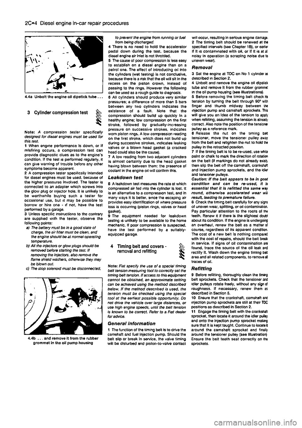
4.4a Unbolt the engine oil dipstick tube...
3 Cylinder compression test
Note: A compression tester specifically designed for diesef engines must be used for this test. 1 When engine performance Is down, or if misfiring occurs, a compression test can provide diagnostic clues as to the engine's condition, If the lest is performed regularly, it can give warning of trouble before any other symptoms become apparent. 2 A compression tester specifically Intended for diesel engines must be used, because of the higher pressures involved. The Ie6ter is connected to an adapler which screws Into the glow plug or injector hole. It is unlikely to be worthwhile buying such a tester for occasional use. but it may be possible to borrow or hire one • if not. have the test performed by a garage. 3 Unless specific instructions to the contrary are supplied with the tester, observe the following points: 9) The battery must bo in a good state of charge, the air titter must be clean, end the engine should be at normal operating temperature. b) AH the in/actors or glow plugs should be removed before starting the lest. If removing the injectors, also remove the flame shield washers, otherwise they may be blown out. c) The stop solenoid must be disconnected.
4.4b ... and remove it from the rubber grommet in the oil pump housing
fo prevent the engine from running or fuel from being discharged. 4 There is no need to hold the accelerator pedal down during the test, because the diesel engine air inlet is not throttled. 5 The cause of poor compression Is less easy to establish on a diesel engine than on a petrol one. The effect of introducing oil into the cylinders (wet testing) Is not conclusive, because there is a risk that the oil will sit in the recess on the piston crown, instead of passing to the rings. However the following can be used as a rough guide to diagnosis. 6 All cylinders should produce very similar pressures; a difference of more than 5 bars between any two cylinders Indicates the existence of a fault. Note that the compression should build up quickly In a healthy engine; low compression on the first stroke, followed by gradually-increasing pressure on successive strokes, indicates worn piston rings. A low compression reading on the first stroke, which does not build up during successive strokes, indicates leaking valves or a blown head gasket (a cracked hoad could also be the cause). 7 A low reading from two adjacent cylinders Is almost certainly due to the head gasket having blown between them: the presence of coolant In the engine oil will confirm this,
Leakdown test 8 A leakdown test measures the rate at which compressed air fed into the cylinder Is lost. It is an alternative to a compression test, and in many ways it is better, since the escaping air provides easy identification of where pressure loss is occurring (piston rings, valves or head gasket). 9 The equipment needed for leakdown testing is unlikely to be available to the home mechanic. If poor compression Is suspected, have the test performed by a suitably-equipped garage.
4 Timing belt and covers -removal
and
refitting
Note: Fiat specify the use of a spec/a/ timing belt tension measuring tool to correctly set the timing belt tension. If access to this equipment cannot be obtained, an approximate setting can be achieved using the method described below. If the method described is used, the tension must be checked using the special tool at the earliest possible opportunity. Do not drive the vehicle over large distances, or use high engine speeds, until the belt fens/on rs known to be correct. Refer to a Fiat dealer for advice.
General Information 1 The function of the timing belt is to drive the camshaft and fuel injection pump. Should the belt slip or break in service, the valve timing will be disturbed and piston-to-valve contact
will occur, resulting In serious engine damage. 2 The timing bolt should be renewed at the specified intervals (see Chapter 1B), or earlier If It is contaminated with oil. or If It is at al noisy In operation (a scraping noise due to uneven wear),
Removal 3 Set the engine at TDC on No 1 cylinder
as
described in Section 2. 4 Unbolt and remove tho engine oil dipstick tube and remove It from the rubber gromme! in the oil pump housing (see illustrations), 5 Before removing the timing belt check rts tension by turning the belt through 90" with finger and thumb midway between u* injection pump and camshaft sprockets. This will give you an Idea of the tension to apply when refitting, assuming the tension is already correct. Also note the position of the tensions pulley as a reference mark. 6 Release tho nut on the timing bea tensioner, move the tensioner pulley away from the belt and retlghten the nut to hold the pulley in the retracted position. 7 If the timing belt is to be re-used, use white paint or chalk to mark the direction of rotation on the belt (if markings do not already exist), then slip the belt off the camshaft, crankshaft and injection pump sprockets, and the idler and tensioner pulleys. Caution: If the belt appears to be In good condition and can be re-used, it fs essential that It Is refitted the same
wsy
round, otherwise accelerated wear will result, leading fo premature failure. 8 Check the timing belt carefully for any signs of uneven wear, splitting, or oil contamination. Pay particular attention to the roots of the teeth. Renew it if there is the slightest doutt about its condition. If the engine is undergoing an overhaul, renew the belt as a matter of course, regardless of its apparent conditio*. The cost of a new belt Is nothing compa/ed with the cost of repairs, should the belt freak in service. If signs of oil contamination art found, trace the source of the oil leak and rectify It. Wash down the engine timing baft area and all related components, to remove
sd
traces of oil.
Refitting 9 Before refitting, thoroughly clean the tknmg belt sprockets. Check that the tensioner and idler pulleys rotate freely, without any sign ol roughness. If necessary, renew them as described in Section 5. 10 Ensure that the crankshaft, camshaft and injection pump sprockets are still at their TDC positions as described In Section 2. 11 Engage the timing belt with the crankshaft sprocket, then locate it around the idler pufiey and onto the Injection pump sprocket making sure that it is kept taught. Continue to locate! around the camshaft sprocket and finally around Ihe tensioner pulley (see Illustration) Ensure the belt teeth seat correctly on Ihe sprockets.
Page 94 of 225
2D*10 Engine removal and overhaul procedures
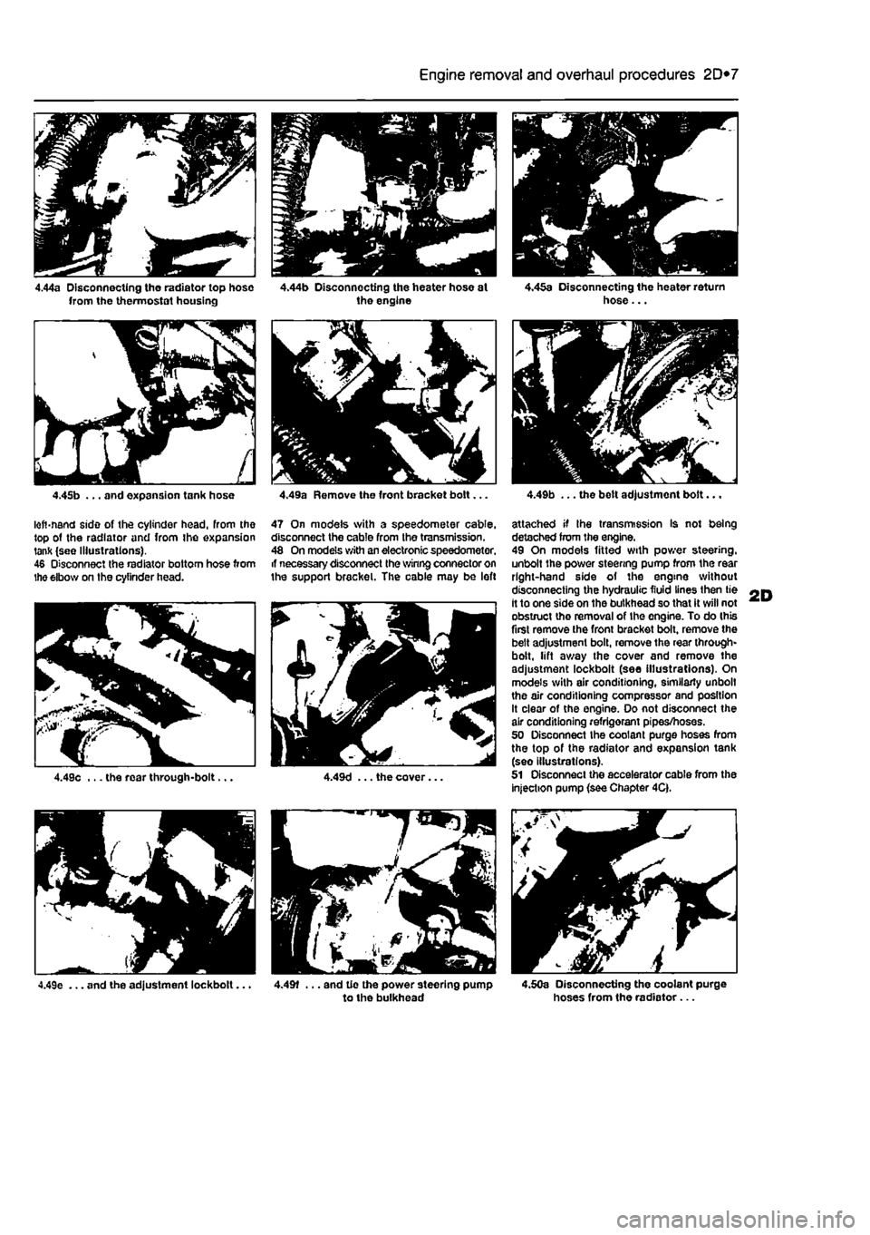
4.44a Disconnecting tho radiator top hose from the thermostat housing
4.45b ... and expansion tank hose
lofi-nand side of the cylinder head, From the top ot the radiator and from the expansion tank (see Illustrations). 46 Disconnect the radiator bottom hose from the elbow on the cylinder head.
4.49e ... and the adjustment lockbolt...
4.44b Disconnecting the heater hose st the engine
4.49a Remove the front bracket bolt...
47 On models with a speedometer cable, disconnect the cable from the transmission. 48 On models with an electronic speedometer, if necessary disconnect the winng connector on the support bracket. The cable may be left
4.49f ... and tie the power steering pump to the bulkhead
. m " • V;
<4
4.45a Disconnecting the heater return hose...
4.49b ... the belt adjustment bolt...
attached if Ihe transmission Is not being detached from the engine. 49 On models fitted with power steering, unbolt the power steering pump from the rear right-hand side of the engine without disconnecting the hydraulic fluid lines then tie it to one side on the bulkhead so that it will not obstruct the removal of the engine. To do (his first remove the front bracket bolt, remove the belt adjustment bolt, remove the rear through-bolt, lift away the cover and remove the adjustment lockbolt (see illustrations). On models with air conditioning, similarly unbolt the air conditioning compressor and position It clear of the engine. Do not disconnect the air conditioning refrigerant pipes/hoses. 50 Disconnect the coolant purge hoses from the top of the radiator and expansion tank (seo illustrations). 51 Disconnect the accelerator cable from the injection pump (see Chapter 4Q.
4.50a Disconnecting the coolant purge hoses from the radiator...
Page 109 of 225
2D*10 Engine removal and overhaul procedures
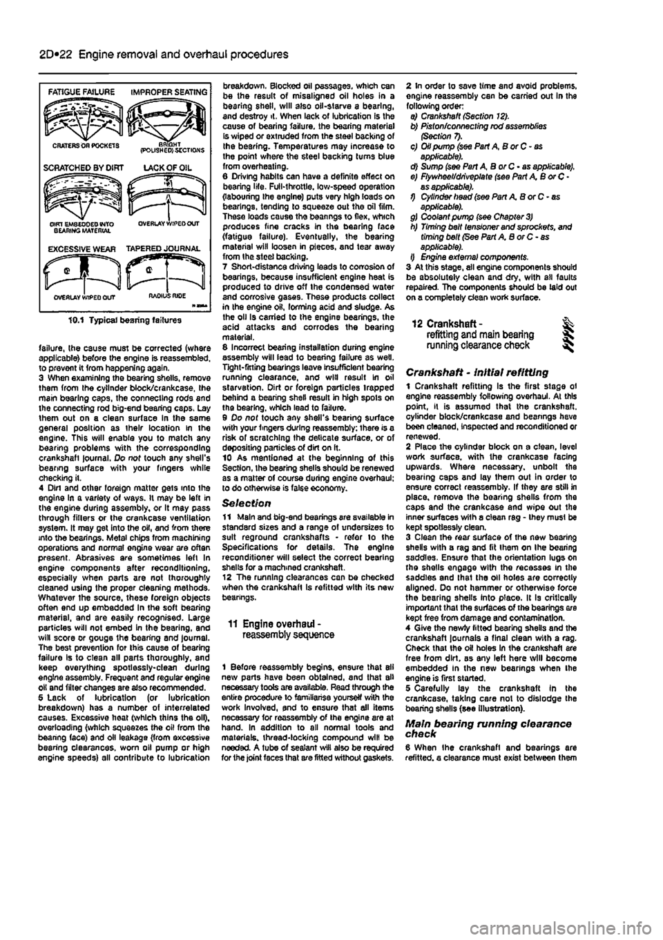
failure, (he cause must be corrected (where applicable) before the engine is reassembled, to prevent it from happening again. 3 When examining the bearing shells, remove them from the cylinder block/crankcase, Ihe main bearing caps, the connecting rods and the connecting rod big-end bearing caps. Lay them out on a clean surface in the same general position as their location in the engine. This will enable you to match any bearing problems with the corresponding crankshaft journal. Do not touch any shell's bearing surface with your fingers while checking it. 4 Din and other foreign matter gets into the engine in a variety of ways. It may be left in the engine during assembly, or It may pass through fillers or the crankcase ventilation system. It may get into the oil, and from there into the bearings. Metal chips from machining operations and normal engine wear are often present. Abrasives are sometimes left In engine components after reconditioning, especially when parts are not thoroughly cleaned using the proper cleaning methods. Whatever the source, these foreign objects often end up embedded In the soft bearing material, and are easily recognised. Large particles will not embed in the bearing, and will score or gouge the bearing and journal. The best prevention for this cause of bearing failure Is to clean all parts thoroughly, and keep everything spotlessly-clean during engine assembly. Frequent and regular engine oil and filter changes are also recommended. 5 Lack of lubrication (or lubrication breakdown) has a number of interrelated causes. Excessive heat (which thins the oil), overloading (which squeezes the oil from the bearing face) and oil leakage (from excessive bearing clearances, worn oil pump or high engine speeds) all contribute to lubrication
breakdown. Blocked oil passages, which can be the result of misaligned oil holes in a bearing shell, will also oil-starve a bearing, and destroy it. When lack of lubrication is the cause of bearing failure, the bearing materiel is wiped or extruded from the steel backing of Ihe bearing. Temperatures may increase to the point where the steel backing turns blue from overheating. 6 Driving habits can have a definite effect on bearing life. Full-throttle, low-speed operation (labouring ihe engine) puts very high loads on bearings, tending to squeeze out the oil film. These loads cause the beanngs to flex, which produces fine cracks in the bearing face (fatigue failure). Eventually, the bearing material will loosen in pieces, and tear away from Ihe steel backing. 7 Short-distance driving leads to corrosion of bearings, because insufficient engine heat is produced to drive off the condensed water and corrosive gases. These products collect in the engine oil, forming acid and sludge. As the oil Is carried to the engine bearings, the acid attacks and corrodes the bearing material. 8 Incorrect bearing installation during engine assembly will lead to bearing failure as well. Tight-fitting bearings leave insufficient bearing running clearance, and will result in oil starvation. Dirt or foreign particles trapped behind a bearing shell result in high spots on the bearing, which lead to failure. 9 Do not touch any shell's bearing surface with your fingers during reassembly: there is a risk of scratching the delicate surface, or of depositing particles of dirt on ft. 10 As mentioned at the beginning of this Section, the bearing shells should be renewed as a matter of course during engine overhaul; to do otherwise is false economy.
Selection 11 Main and big-end bearings are available in standard sizes and a range of undersizes to suit reground crankshafts • refer to the Specifications for details. The engine reconditioner will select the correct bearing shells for a machined crankshaft. 12 The running clearances can be checked when the crankshaft is refitted with its new bearings.
11 Engine overhaul -reassembly sequence
1 Before reassembly begins, ensure that all new parts have been obtained, and that all necessary tools are available. Read through the entire procedure to familiariss yourself with the work Involved, and to ensure that ail items necessary for reassembly of the engine are at hand. In addition to all normal tools and materials, thread-locking compound will be needed. A tube of sealant will also be required for the joint faces that are fitted without gaskets.
2 In order to save time and avoid problems, engine reassembly can be carried out in the following order: a) Crankshaft (Section 12). b) Piston/connecting rod assemblies (Section 7). c) Oil pump (see Part A, B or C - as applicable). d) Sump (see Pan A, BorC-as applicable). e) Flywheel/driveplate (see Part A, B or C • as applicable). 1) Cylinder head (see Part A B or C - as applicable). g) Coolant pump (see Chapter
3)
h) Timing belt tensioner and sprockets, and timing belt (See Part A, B or C- as applicable). I) Engine external components, 3 At this stage, ail engine components should be absolutely clean and dry, with all faults repaired. The components should be laid out on a completely clean work surface.
12 Crankshaft- % refitting and main bearing S running clearance check ^
Crankshaft - initial refitting 1 Crankshaft refitting Is the first stage ol engine reassembly following overhaul. At this point, it is assumed that the crankshaft, cylinder block/crankcase and beanngs have been cleaned, inspected and reconditioned or renewed. 2 Place the cylinder block on a clean, level work surface, with the crankcase facing upwards. Where necessary, unbolt the bearing caps and lay them out in order to ensure correct reassembly. If they are still in place, remove the bearing shells from the caps and the crankcase and wipe out the inner surfaces wilh a clean rag - they musl be kept spotlessly clean. 3 Clean the rear surface of the new bearing shells with a rag and fit ihem on Ihe bearing saddles. Ensure that the orientation lugs on the shells engage with the recesses in the saddles and lhat the oil holes are correctly aligned. Do not hammer or otherwise force the bearing shells into place. It Is critically important that the surfaces of the bearings ore kept free from damage and contamination. 4 Give the newly fitted bearing shells and the crankshaft journals a final clean with a rag. Check that the oil holes In the crankshaft are free from dirt, as any left here will become embedded In the new bearings when Ihe engine is first started. 5 Carefully lay the crankshaft In the crankcase, taking care not to dislodge the bearing shells (see illustration}.
Main bearing running clearance check 8 When Ihe crankshaft and bearings are refitted, a clearance must exist between them
Page 112 of 225
2D*10 Engine removal and overhaul procedures
7 While the engine is idling, check for fuel, water and oil leaks. Don't be alarmed if there are some odd smells and smoke from parts getting hot and burning off oil deposits, ft Assuming alt is well, keep the engine idling until hot water is felt circulating through the bp hose, then switch off the engine.
9 Recheck the oil and coolant levels as described in Chapter 1A or 16, and top-up as necessary. 10 There is no need to re-tighten the cylinder head bolts once the engine has first run after reassembly. 11 If new pistons, rings or crankshaft
bearings have been fitted, the engine must be treated as new. and run-in for the first 500 miles (800 km). Do net operate the engine al full-throttle, or allow it to labour at low engine speeds in any gear. It is recommended that the oil and filter be changed at the end of this period.
2D
Page 113 of 225
3*1
Chapter 3
Cooling, heating and ventilation systems
Contents
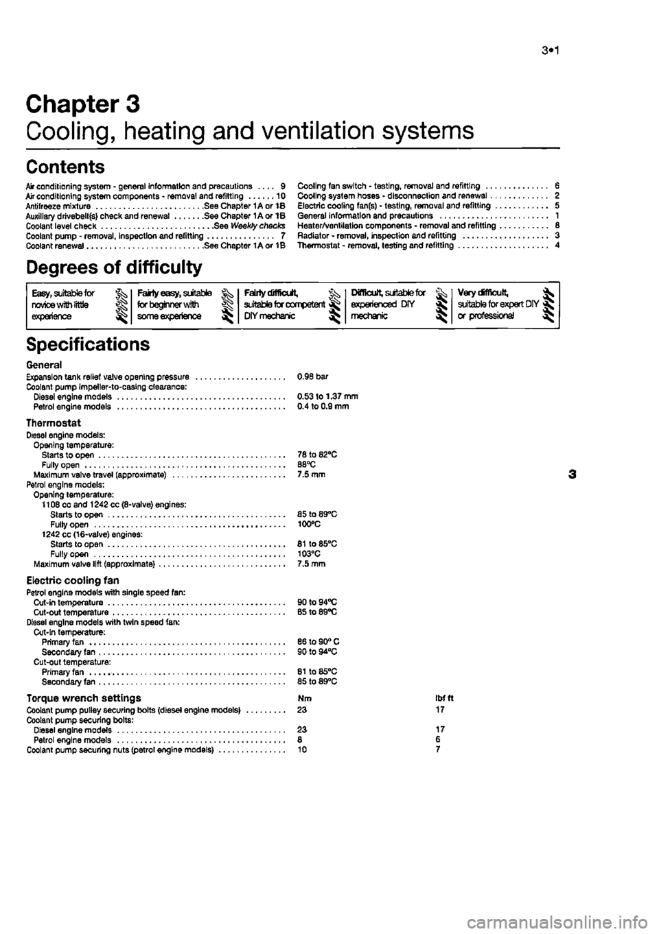
Air conditioning system - general Information and precautions .... 9 Mr conditioning system components * removal and refitting 10 Antifreeze mixture See Chapter 1A or 1B Auxiliary drivebell(s) check and renewal See Chapter 1A or IB Coolant level check See Weekly checks Coolant pump - removal, Inspection and refitting 7 Coolant renewal See Chapter 1A or 1B
Degrees of difficulty
Cooling fan switch - testing, removal and refitting 6 Cooling system hoses • disconnection and renewal 2 Electric cooling fan(s) - testing, removal and refitting 5 General information and precautions 1 Heater/ventilation components • removal and refitting 8 Radiator - removal, inspection and refitting 3 Thermostat - removal, testing and refitting 4
Easy,
suitable foe JS^, novice
with
little experience ^
Fairly
easy,
sutable for beginner witti
some experience
^
Faiilydifltctit,
suitable
for competent
DIY mechanic
^
Difficult,
sutable for & experienced DIY « mechanic ^
VerydMlcult, ^
suitable
for
expert DIY
« or professional
Specifications
General Expansion tank relief valve opening pressure 0.96 bar Coolant pump Impeller-to-casing clearance: Diesel engine models 0.53 to 1.37 mm Petrol engine models 0.4 to 0.9 mm
Thermostat Diesel engine models: Opening temperature: Starts to open 78 to 82*0 Fully open 88°C Maximum valve travel (approximate) 7.5 mm Petrol engine models: Opening temperature: 1108 cc and 1242 cc (8-valve) engines: Starts to open 85 to 89°C Fully open 100°C 1242 cc (16-valve) engines: Starts to open 81 to 85°C Fully open 103°C Maximum valve lift (approximate) 7.5 mm
Electric cooling fan Petrol engine models with single speed fan: Cut-in temperature 90to94°C Cut-out temperature B5 to 89°C Diesel engine models with twin speed fan: Cut-In temperature: Primary fan 86 to 90® C Secondary fan 90 to 94°C Cut-out temperature: Primary fan 81to85°C Secondary fan 85 to 89°C
Torque wrench settings Nm tbfft Coolant pump pulley securing bolts (diesel engine models) 23 17 Coolant pump securing bolts: Diesel engine models 23 17 Petrol engine models 8 6 Coolant pump securing nuts (petrol engine models) 10 7