catal FIAT PUNTO 1994 176 / 1.G User Guide
[x] Cancel search | Manufacturer: FIAT, Model Year: 1994, Model line: PUNTO, Model: FIAT PUNTO 1994 176 / 1.GPages: 225, PDF Size: 18.54 MB
Page 147 of 225

4D*4 Exhaust and emission control systems
d) DO NOT push- or tow-start the car - this will soak the catalytic converter
in
unbumed fuel, causing It to overheat when the engine does start. e) DO NOT switch off the ignition at high engine speeds. f) DO NOT use fuel or engine oil additives -these may contain substances harmful to the catalytic converter. g) DO NOT continue to use the car If
the
engine bums oil to the extent of leaving
a
visible trail of blue smoke.
h) Remember that the catalytic converter operates at very high temperatures. DO NOT, therefore, park the car in dry undergrowth, over long grass or piles of deed leaves after a long run. I) Remember that the catalytic converter is FRAGILE - do not strike it with tools during servicing work, j} In some cases a sulphurous smell
pike
that of rotten eggs) may be noticed from the exhaust. This Is common to many catalytic converter-equipped cars and
once the car has covered a few
thousand
miles tha problem should
disappear,
k)
The
catalytic converter, used on a
weW*
maintained and well-driven car, should las for between
SO
000 and
100
000
miles-If
the converter is no longer effective It
must
be renewed.
Diesel models Refer to the information given in parts i,
g, h
and I of the petrol models information given above.
Page 198 of 225

10*10 Suspension and steering
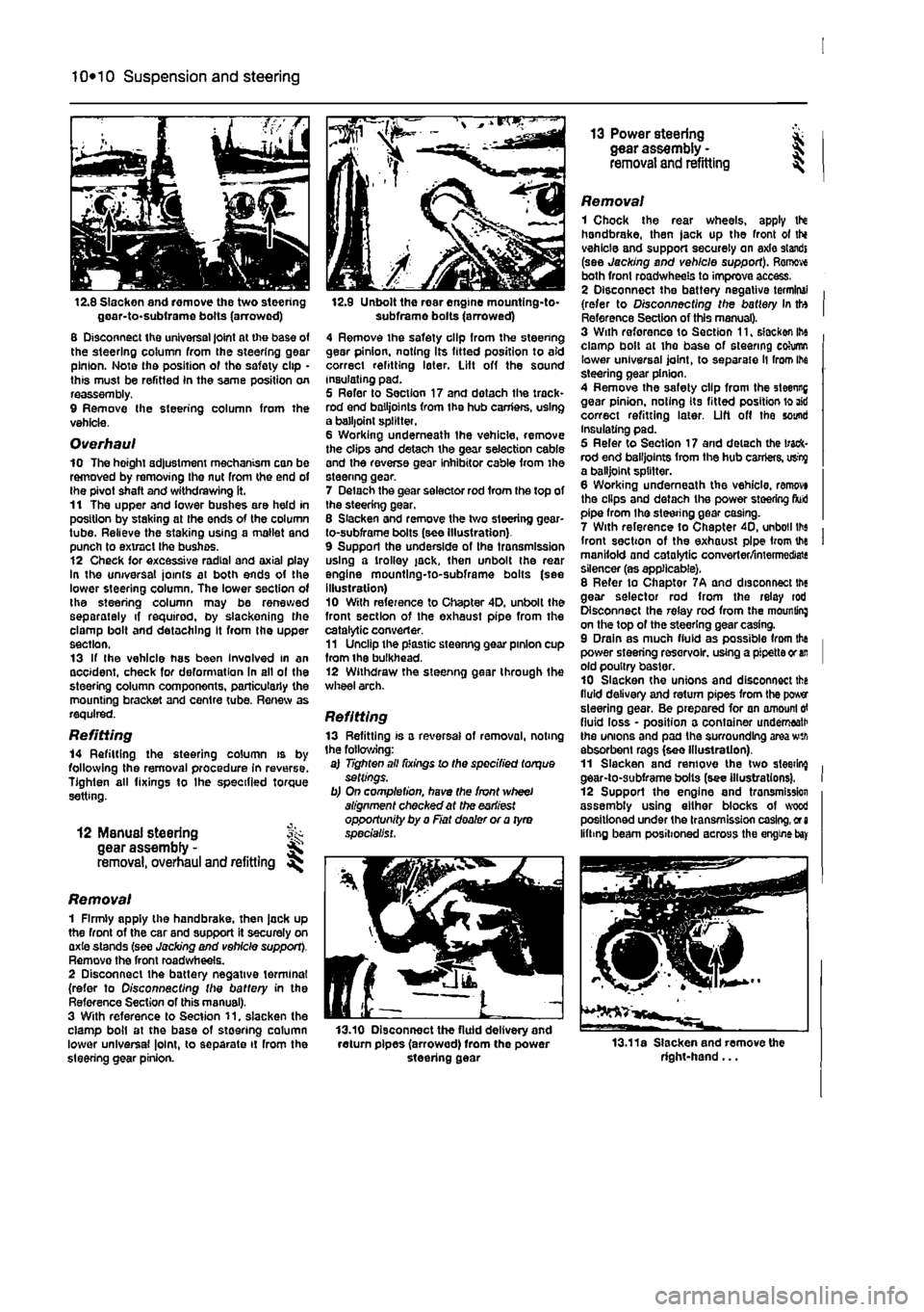
12.8 Slacken and remove the two steering goar-to-subirame bolts (arrowed) 8 Disconnect the universal joint at the base of the steering column from the steering gear pinion. Note the position of tho safety clip • this must be refitted In the same position on reassembly. 9 Remove Ihe steering column from the vehicle.
Overhaul 10 The hoight adjustment mechanism can be removed by removing the nut from the end of the pivot shaft and withdrawing it. 11 The upper and lower bushes are held in position by staking at the ends of the column tube. Relieve the staking using a mallet and punch to extract the bushes. 12 Check for excessive radial and axial play In the universal joints at both ends of the lower steering column. The lower section of the steering column may be renewed separately if required, by slackening the clamp bolt and detaching It from the upper section. 13 If the vehicle has been Involved in an accident, check for deformation In all ol the steering column components, particularly the mounting bracket and centre tube. Renew as required.
Refitting 14 Refitting the steering column is by following the removal procedure in reverse. Tighten all fixings to Ihe specified torque setting.
12 ManuaJ steering fk gear assembly -removal, overhaul and refitting
Removal 1 Firmly apply the handbrake, then jack up the front of the car and support it securely on axie stands (see Jacking and vehicle support). Remove the front road wheels. 2 Disconnect the battery negative terminal (refer to Disconnecting the battery in the Reference Section of this manual). 3 With reference to Section 11. slacken the clamp boil at the base of steering column lower universal |o!nt, to separate it rrom the steering gear pinion.
12.9 Unbolt the rear engine mountlng-to-subframe bolts (arrowed) 4 Remove the safety clip from the steering gear pinion, noting Its fitted position to aid correct refitting later. Lift off the sound insulating pad. 5 Refer to Section 17 and dotach the track* rod end bailjoints from the hub carriers, using a balljoint splitter. 6 Working underneath the vehicle, remove the clips and detach the gear selection cable and the reverse gear inhibitor cable from the steenng gear. 7 Delach the gear selector rod from the top of the steering gear, 8 Slacken and remove the two steering gear-to-subframe bolts (see Illustration) 9 Support the underside of the transmission using a trolley jack, then unbolt the rear engine mountlng-to-subframe bolts (see illustration) 10 With reference to Chapter 4D. unbolt the front section of the exhaust pipe from the catalytic converter. 11 Unclip the plastic steenng gear pinion cup from ihe bulkhead. 12 Withdraw the steenng gear through the wheel arch.
Refitting 13 Refitting is a reversal of removal, noting the following: a) Tighten all fixings lo the specified torque settings. b) On completion, have the front wheel alignment checked at the earliest opportunity by a Fiat dealer or a tyro specialist.
13.10 Disconnect the fluid delivery and return pipes (arrowed) from the power steering gear
13 Power steering * gear assembly - J removal and refitting ^
Removal 1 Chock the rear wheels, apply tN handbrake, then jack up the front ot thi vehicle and support securely on axle standi (see Jacking and vehicle support). Remove both front roadwheels to improve access. 2 Disconnect the battery negative terminal (refer to Disconnecting the battery In tto Reference Section of this manual). 3 With reforence to Section 11, slacken ihe clamp bolt at the base of steering cohimn lower universal joint, to separate ll from Ihe steering gear pinion. 4 Remove the safety clip from the steenng gear pinion, noting its fitted position lo aid correct refitting later. Lift off the sound Insulating pad. 5 Refer to Section 17 and detach the track-rod end bailjoints from the hub carriers, usty a balljoint splitter. 6 Working underneath the vehicle, ranwvi the clips and detach the power steering fluid pipe from the steering gear casing. 7 With reference to Chapter 40, unboil lbs front section of the exhaust pipe from the manifold and catalytic converter/intermediate silencer (as applicable). 8 Refer to Chaptor 7A and disconnect the gear selector rod from the relay rod Disconnect the relay rod from the mounting on the top of the steering gear casing. 9 Drain as much fluid as possible from the power steering reservoir, using a pipette or
an
old poultry baster. 10 Slacken the unions and disconnect the fluid delivery and return pipes from the power steering gear. Be prepared for an amount
erf
fluid loss - position a container underneath the unions and pad the surrounding area wth absorbent rags (see Illustration). 11 Slacken and remove the two sleeting gear-to-subframe bolts (see illustrations). 12 Support the engine and tronsmission assembly using either blocks of wood positioned under the transmission casing,
or a
lifting beam positioned across the engine
bay
13.11a Slacken and remove the right-hand...