catal FIAT PUNTO 1994 176 / 1.G Workshop Manual
[x] Cancel search | Manufacturer: FIAT, Model Year: 1994, Model line: PUNTO, Model: FIAT PUNTO 1994 176 / 1.GPages: 225, PDF Size: 18.54 MB
Page 2 of 225
Fiat Punto
Service and Repair Manual
A K Legg LAEMIMI and Spencer Drayton
Models covered P251 •272 • WAC2>
Fiat Punto Hatchback, including Selecta and special/limited editions Petrol engines: 1.1 litre (1108 cc) and 1,2 litre (1242 cc, 8-valve and 16-valve) Diesel & turbo-dlesel engines: 1.7 litre (1698 cc)
Does NOT cover 1.4 litre (1372 cc) or 1.6 litre (1581 cc) petrol engines, or Cabriolet
©Haynos Publishing 1999 KLWH A book in the Haynes Service end Ropalr Manual Series
All rights reserved. No part of this book may bo reproduced or transmitted in any form or by any means, electronic or mechanical, Including photocopying, recording or by any information storage or retrieval system, without permission In writing from the copyright hokJer.
ISBN 1 85960 561 3
British Library Cataloguing tn Publication Data A catalogue record for this book Is available from the British Ubrary.
Printed by J H Haynes & Co. Ltd, Sparkford, Nr Yeovil, Somerset BA22 7JJ
Haynes Publishing
Sparkford. Nr Yeovil. Somerset BA22 7JJ, England
Haynes North America, Inc
681 Lawrence Drive, Newbury Park. Califomio 91320. USA
Editions Haynes S.A. Tour Aurora - La
D6
expert22 fl/i* http://rutracker.org
Page 10 of 225
Roadside repairs 0.9
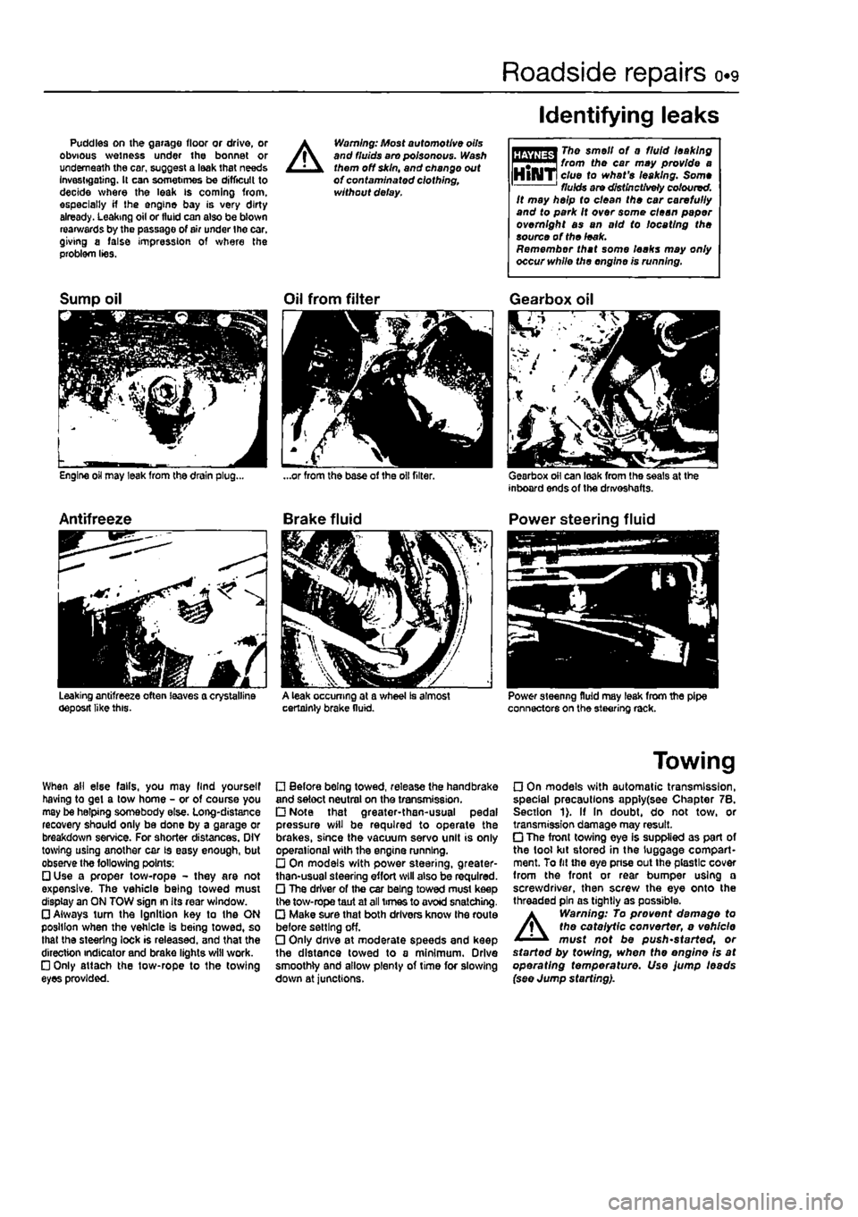
Puddles on the garage floor or drive, or obvious wetness under the bonnet or underneath the car, suggest a leak that needs Investigating. It can sometimes be difficult to decide where the leak is coming from, especially if the engine bay is very dirty already. Leaking oil or fluid can also be blown rearwards by the passage of air under the car, giving a false impression of where the problem lies.
A
Warning: Most automotive oils and fluids aro poisonous. Wash them off skin, and change out of contaminated clothing, without delay.
Identifying leaks
The smell of 0 fluid leaking from the car may provide a clue to what's leaking. Some fluids are distinctively coloured. It may help to clean the car carefully and to park It over some clean paper overnight as an aid to locating the source of the leak. Remember that some leaks may only occur while the engine is running.
Sump oil
Engine oil may leak from the drain plug...
Antifreeze
Leaking antifreeze often leaves a crystalline oeposit like this.
Oil from filter
A leak occurring at a wheel Is almost certainly brake fluid.
Gearbox oil
Gearbox oil can leak from the seals at the inboard ends of the drivoshafts.
Power steering fluid
Power steering fluid may leak from the pipe connectors on the steering rack.
When ail else falls, you may llnd yourself having to get a tow home - or of course you may be helping somebody else. Long-distance recovery should only be done by a garage or breakdown service. For shorter distances. OIY towing using another car is easy enough, but observe the following points: • Use a proper tow-rope - they are not expensive. The vehicle being towed must display an ON TOW sign in its rear window. • Always turn the Ignition key to the ON position when the vehicle is being towed, so that the steering lock is released, and that the direction indicator and brake lights will work. • Only attach the tow-rope to the towing eyes provided.
• Before being towed, release the handbrake and select neutral on the transmission. • Note that greater-then-usual pedal pressure will be required to operate the brakes, since the vacuum servo unit is only operational with the engine running. • On models with power steering, greater-than-usual steering effort will also be required. • The driver of the car being towed must keep the tow-rope taut at all times to avoid snatching. • Make sure that both drivers know the route before setting off. • Only dnve at moderate speeds and keep the distance towed to a minimum. Drive smoothly and allow plenty of time for slowing down at junctions.
Towing
• On models with automatic transmission, special precautions apply(see Chapter 7B. Section 1). If In doubt, do not tow, or transmission damage may result. • The front towing eye is supplied as part of the tool kit stored in the luggage compart-ment. To fit the eye pnse out the plastic cover from the front or rear bumper using a screwdriver, then screw the eye onto the threaded pin as tightly as possible.
A
Warning: To prevent damage to the catalytic converter, e vehicle must not be push'started, or started by towing, when the engine is at operating temperature. Use jump leads (see Jump starting).
Page 33 of 225
ia.14 Every 20 000 miles - petrol models
16 Test the operation of the brake servo unit as follows. With the engine off, depress the footbrake four or five times to exhaust the vacuum. Hold the brake pedal depressed, then start the engine. As the engine starts.
there should be a noticeable give In the brake pedal as vacuum builds up. Allow the engine to run for at least tsvo minutes, and then switch it off. If the brake pedal is depressed now. it should be possible to detect a hiss
from the servo as the pedal is depressed. After about four or five applications, no further hissing should be heard, and the pedal shouto feel considerably harder.
Every 30 000 miles (45 000 km) or 3 years
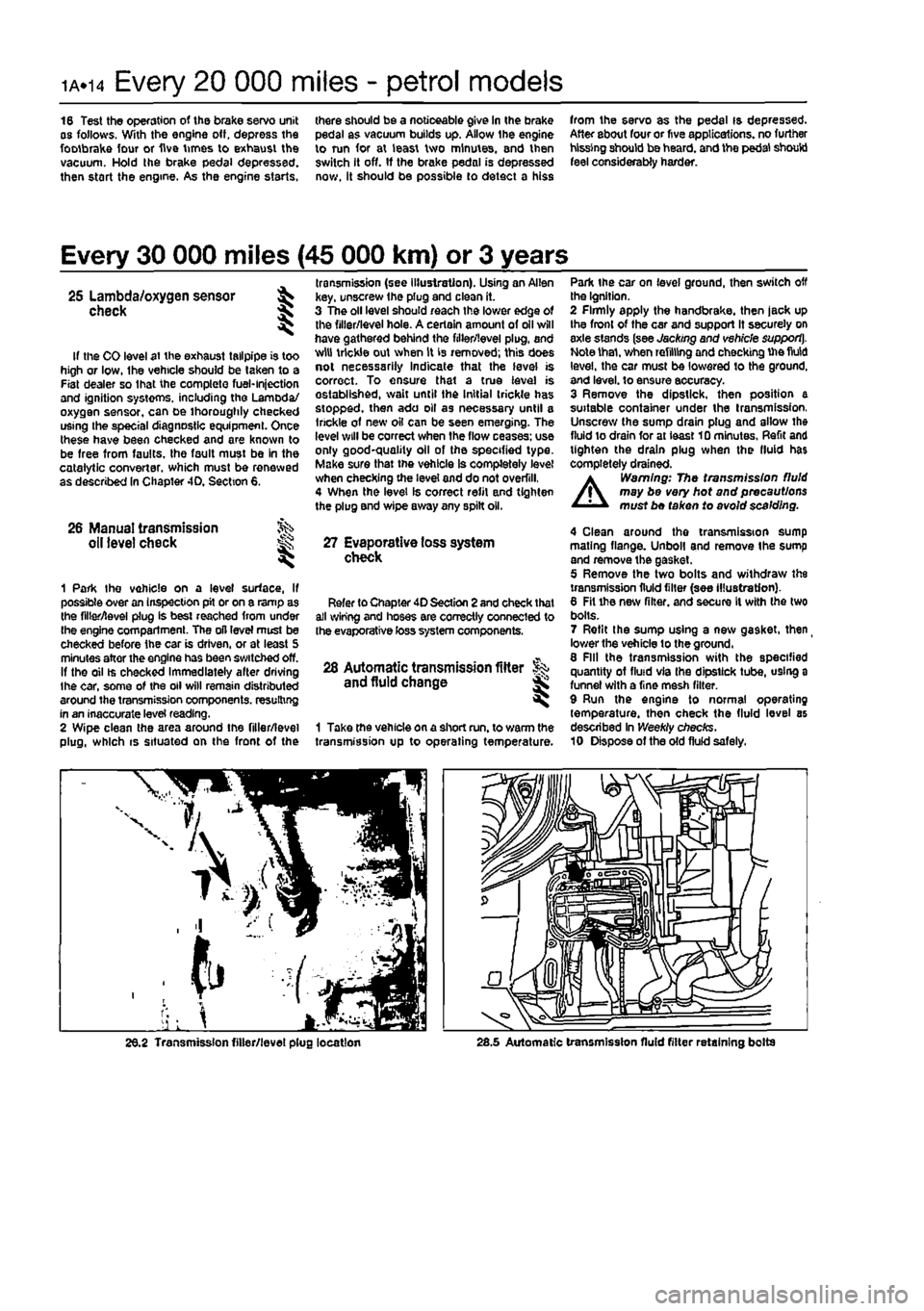
. transmission (see illustration). Using an Allen 25 Lambda/oxygen sensor ^ key, unscrew the plug and clean it. check \ 3 The oil level should reach the lower edge of ^ the filler/level hole. A certain amount of oil will have gathered behind the filler/level plug, and If the CO level at the exhaust tailpipe is too w,u tr,cWe out when is 'e™oved; this does high or low, Ihe vehicle should be taken to a «©l necessarily Indicate that the level is Fiat dealer so lhat the complete fuel-injection correct. To ensure that a true level is and ignition systems, including the Lamoda/ established, wait until the Initial trickle has oxygen sensor, can be thoroughly checked stopped, then ado oil as necessary until a using the special diagnostic equipment. Once ,r,ckle o1 new oil can be seen emerging. The these have been checked and are known to 'W wl" be correct when ,he flow ceases-us® be free from faults, the fault must be in the good-quality oil of the specified type, catalytic converter, which must be renewed Make sur®that vehicle Is completely level as described In Chapter 4D, Section 6. checking the level and do not overfill, 4 When the level Is correct refit and tighten the plug and wipe away any spilt oil.
26 Manual transmission oil level check ^ 27 Evaporative loss system ^ check
1 Park Ihe vehicle on a level surface, If possible over an inspection pit or on a ramp as the filler/level plug is best reached from under Ihe engine compartment. The oil level must be checked before the car is driven, or at least 5 minutes after the engine has been switched off. If the oil ts checked Immediately alter driving the car, some of the oil will remain distributed around the transmission components, resulting in an inaccurate level reading. 2 Wipe clean the area around the filler/level plug, which is situated on the front of the
Refer to Chapter 40 Section 2 and check that all wiring and hoses are correctly connected to the evaporative toss system components.
28 Automatic transmission fitter and fluid change
1 Take the vehicle on a short run. to warm the transmission up to operating temperature.
Park the car on level ground, then switch off the Ignition. 2 Firmly apply the handbrake, then jack up the front of the car and support It securely on axle stands (see Jacking and vehicle support]. Note thai, when refilling and checking Uie fluid level, the car must be lowered to the ground, and level, to ensure accuracy. 3 Remove the dipstick, then position a suitable container under the transmission, Unscrew the sump drain plug and allow the fluid to drain for at ieast 10 minutes. Refit and tighten the drain plug when the fluid has completely drained.
A
Warning: The transmission fluid may be very hot and precautions must be taken to avoid scalding.
4 Clean around the transmission sump mating flange. Unboll and remove the sump and remove the gasket. 5 Remove the two bolts and withdraw the transmission fluid filter {see illustration). 6 Fit the new filter, and secure It with the two bolts. 7 Refit the sump using a new gasket, then
_
lower the vehicle to the ground, 8 Fill the transmission with the specified quantity of fluid via Ihe dipstick tube, using a funnel with a fine mesh filter. 9 Run the engine to normal operating temperature, then check the fluid level as described In Weekly checks. 10 Dispose of the old fluid safely.
26.2 Transmission filler/level plug location 28.5 Automatic transmission fluid filter retaining bolts
Page 122 of 225
4A*2 Fuel system - single-point petrol Injection models
1 General information and precautions
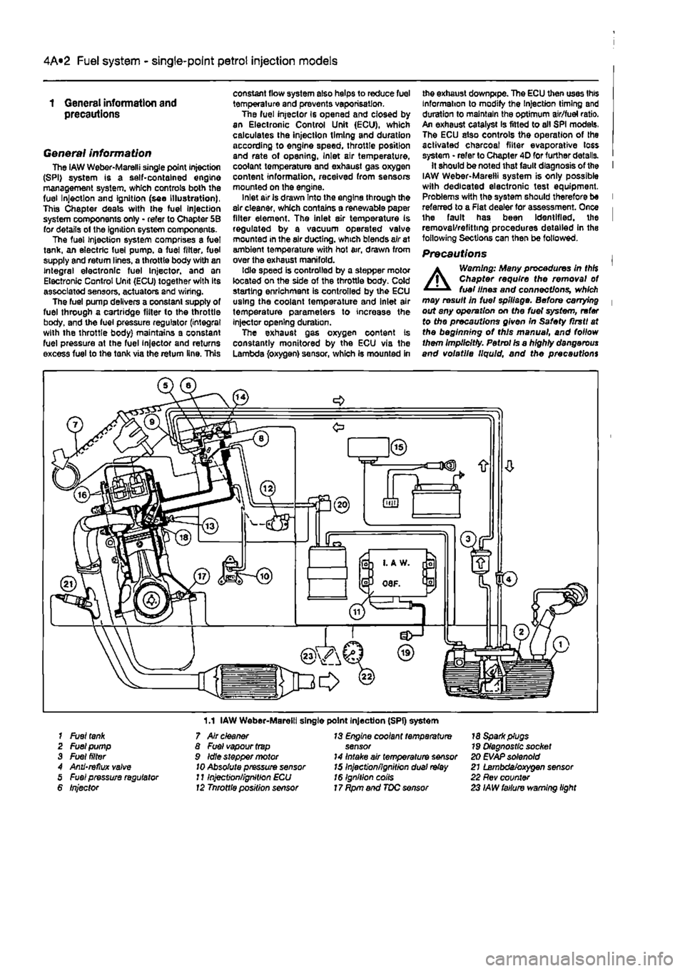
General information The iAW Weber-Marelli single point Injection (SPI) system is a self-contained engine management system, which controls both the fuel Injection and Ignition (see Illustration), This Chapter deals with the fuel Injection system components only - refer to Chapter 5B for details ol the ignition system components. The fuel Injection system comprises a fuel tank, an electric fuel pump, a fuel filter, fuel supply and return lines, a throttle body with an integral electronic fuel Injector, and an Electronic Control Unit (ECU) together with its associated sensors, actuators and wiring. The fuel pump delivers a constant supply of fuel through a cartridge fitter to the throttle body, and the fuel pressure regulator (integral with the throttle body) maintains a constant fuel pressure at the fuel injector and returns excess fuel to the tank via the return line. This
constant flow system also helps to reduce fuel temperature and prevents vaporisation. Tne fuel injeclor Is opened and closed by an Electronic Control Unit (ECU), which calculates the injection timing and duration according to engine speed, throttle position and rate of opening, Inlet air temperature, coolant temperature and exhaust gas oxygen content information, received from sensors mounted on the engine. inlet air is drawn Into the engine through the air cleaner, which contains a renewable paper filter element. The inlet air temperature is regulated by a vacuum operated valve mounted in the air ducting, which blends air at ambient temperature with hot air, drawn from over the exhaust manifold. Idle speed is controlled by a stepper motor located on the side of the throttle body. Cold starling enrichment is controlled by the ECU using the coolant temperature and inlet air temperature parameters to increase the injector opening duration. The exhaust gas oxygen content is constantly monitored by the ECU via the Lambda (oxygen) sensor, which is mounted in
me exhaust downpipe. The ECU then uses this Information to modify the Injection timing and duration to maintain the optimum air/fuel ratio. An exhaust catalyst Is fitted to all SPI models. The ECU also controls the operation of the activated charcoal filter evaporative loss system • refer to Chapter 4D for further details. It should be noted that fault diagnosis of the I IAW Weber-Marelli system is only possible with dedicated electronic test equipment. Problems with the system should therefore be I referred to a Flat dealer for assessment. Once i the fault has been Identified, the I removal/refitting procedures detailed in the following Sections can then be followed.
Precautions |
A
Warning: Many procedures in thH Chapter require the removal ot fuel lines and connections, which may result in fuel spillage. Before carrying | out any operation on Me fuel system, refer to the precautions given In Safety flrstt at the beginning ot this manual, and follow them Implicitly. Petrol Is a highly dangerous and volatile liquid, and the precautions
1.1 IAW Weber-Marelli single point Injection (SPI) system 1 Fuel
tank
2 Fuel pump 3 Fuel filter 4 Anii'reflux valve 5 Fuel pressure regulator 6 Injector
7 Air cleaner 8 Fuel vapour
trap
9 Idle stepper motor
10
Absolute pressure sensor J11njection/ignition ECU 12 Tnrottle position sensor
13 Engine coolant temperature sensor 14 Intake air temperature sensor 15 Inject'onfignitron dual
relay
16 Ignition coils 17 Rpm and TDC sensor
18 Spark plugs 79 Diagnostic socket 20 EVAP solenoid 21 Lambda/oxygen sensor 22 Rev counter 23 IAW failure warning light
Page 126 of 225
4A*2 Fuel system - single-point petrol Injection models
1 The luel system referred to In this Section is defined as the tank-mounted fuel pump, the fuel litter, the throttle body and pressure regulator components, and the metal pipes and flexible hoses of the fuel lines between these components. All ihese contain fuel which will be under pressure while the engine Is running and/or while tha Ignition is switched on. The pressure will remain for some time after tho ignition has been switched off, and must be relieved before any of these components are disturbed (or servicing work. 2 Disconnect the battery negative terminal (refer to D/sconnecf/ngr the battery in the Reference Section of this manual), 3 Place a container beneath the relevant connection/union to be disconnected, and have a large rag ready to soak up any escaping fuel not being caught by the container. 4 Slowly loosen the connection or union nut (as applicable) to avoid a sudden release of pressure, and wrap tho rag around the connection to catch any fuel spray which may be expelled. Once the pressure is released, disconnect the fuel line, and Insert plugs to minimise fuel loss and prevent the entry of dirt Into the fuel system.
9 Inlet manifold -removal and refitting ^
Note: Refer to the warning given In Section 1 before proceeding.
Removal 1 Remove the throttle body assembly as described in Section 5. 2 Drain the cooling system as described in Chapter 1A. 3 Disconnect the winng connector from the coolanl temperature sensor (situated on the left-hand sidB of the manifold). 4 Undo the bolt securing the accelerator cable mounting bracket to the manifold, and position it clear of the manifold. 5 Slacken the retaining clip and disconnect tha coolant hose from the rear of the manifold. 6 Disconnect the brake vacuum hose. 7 Undo the seven manifold retaining nuts and
10.2 The diagnostic connector la located behind the ECU bolts, and remove (he manifold from the engine. Remove the gasket and discard It; a new one should be used on refitting.
Refitting 8 Refitting is a reverse of the removal procedure, noting the following points: a) Ensure that the manifold and cylinder head mating surfaces are clean and dry, and fit a nev/ manifold gasket. Refit the manifold and securely tighten Its retaining nuts. b) Ensure that all relevant hoses are reconnected fo their original positions and are securely held (where necessary) by the retaining clips. c) Refit the throttle body assembly with reference to Section S. d) On completion, refill the cooling system as described In Chapter 1A.
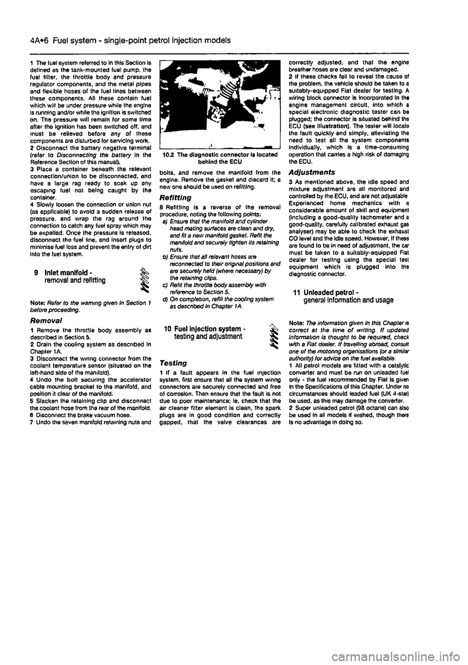
correctly adjusted, and that the engine breather hoses are clear and undamaged. 2 If these checks fall to reveal the cause of the problem, the vehicle should be taken to a suitably-equipped Fiat dealer for testing. A wiring block connector Is Incorporated In the engine management circuit, into which a special electronic diagnostic tester can be plugged; the connector is situated behind the ECU (see Illustration). The tester will locate the fault quickly and simply, alleviating the need to test all the system components Individually, which is a time-consuming operation that carries a high risk of damaging the ECU.
Adjustments 3 As mentioned above, the idle speed and mixture adjustment are all monitored and controlled by the ECU, and are not adjustable Experienced home mechanics with a considerable amount of skill and equipment (including a good-quality tachometer and a good-quality, carefully calibrated exhaust gas analyser) may be able to check the exhaust CO level and ihe idle speed. However, If thes* are found lo be in need of adjustment, the car must be taken to a suitably-equipped Flat dealer for testing using the special test equipment which is plugged into the diagnostic connector.
11 Unleaded petrol -general Information and usage
10 Fuel injection system - & testing and adjustment S
Testing 1 If a fault appears in the fuel injection system, first ensure that all the system winng connectors are securely connected and free of corrosion. Then ensure that the fault Is not due to poor maintenance; ie, check that the air cleanor fitter element is clean, the spark plugs are In good condition and correctly gapped, that tho valve clearances are
Note: The information given in this Chapter
is
correct at the time of writing. If updated Information is thought to be required, check with a Fiat dealer. If travelling abroad, consult one of the motonng organisations (or a similar authority) for advice on the fuel available. 1 All petrol models are fitted with a catalytic converter and must be run on unleaded fuel only - the fuel recommended by Flat is given In the Specifications of this Chapter. Under no circumstances should leaded fuei (UK 4-slar) be used, as this may damage the converter. 2 Super unleaded petrol (98 octane) can also be used in all models if wished, though there is no advantage in doing so.
Page 128 of 225
4A*2 Fuel system -
single-point
petrol Injection models
1 General information and precautions
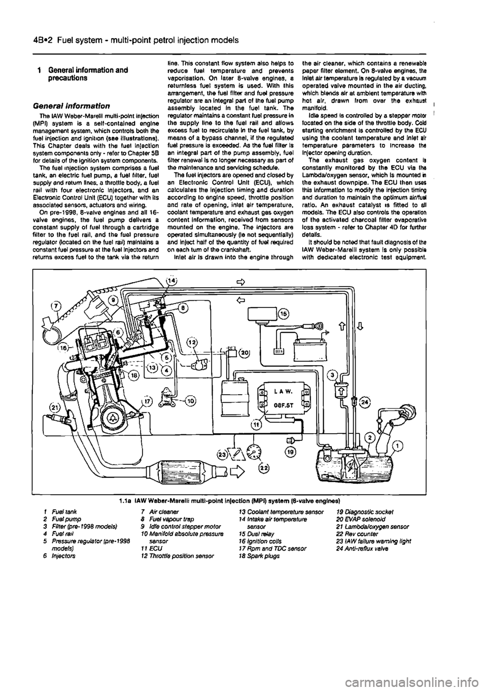
General information The
LAW
Weber-Maretil multi-point Injection (MPI) system is a self-contained engine management system, which controls both the fuel injoction and Ignition (see Illustrations). This Chapter deals with the fuel Injection system components only - refer to Chapter 5B for details of the ignition system components. The fuel injection system comprises a fuel tank, an electric fuel pump, a fuel filter, fuel supply end return lines, a throttle body, a fuel rail with four electronic Injectors, and an Electronic Control Unit (ECU) together with its associated sensors, actuators and wiring. On pre-1998, 8-valve engines and all 16-valve engines, the fuel pump delivers a constant supply of fuel through a cartridge filter to the fuel rail, and the fuel pressure regulator (located on Ihe fuel rail) maintains a constant fuel pressure at the fuel Injectors and returns excess fuel to the tank via the return
line, This constant flow system also helps to reduce fuel temperature and prevents vaporisation. On later 8-valve engines, a returnless fuel system is used. With this arrangement, the fuel filter and fuel pressure regulator are an integral part of the fuel pump assembly located In the fuel tank. The regulator maintains a constant fuel pressure in the supply line lo the fuel rail and allows excess fuel to recirculate in the fuel tank, by means of a bypass channel, if the regulated fuel pressure is exceeded. As the fuel filler Is an integral part of the pump assembly, fuel filter renewal Is no longer necessary as part of the maintenance and servicing schedule. The fuel injectors are opened and closed by an Electronic Control Unit (ECU), which calculates the Injection timing and duration according to engine speed, throttle position and rate of opening, inlet air temperature, coolant temperature and exhaust gas oxygen content information, received from sensors mounted on the engine. The injectors are operated simultaneously (le not sequentially) and Inject half of the quantity of fuel required on each turn of the crankshaft. Inlet air Is drawn into the engine through
the air cleaner, which contains a renewable paper filter element. On 8-valve engines, the Inlet air temperature is regulated by a vacuum operated valve mounted in the air ducting, which blends air at ambient temperature with hot air, drawn Irom over the exhaust | manifold. Idle speed Is controlled by a stepper motor 1 located on the side of the throttle body. Cold storting enrichment is controlled by the ECU using the coolant temperature and Inlet air temperature parameters to Increase the Injector opening duration. The exhaust gas oxygen content it constantly monitored by the ECU via the Lambda/oxygen sensor, whioh Is mounted in the exhaust downpipe. The ECU then uses this Information to modify the Injection timing and duration to maintain the optimum air/fuel ratio. An exhaust catalyst is fitted to all models. The ECU also controls the operation of the activated charcoal filler evaporative loss system - refer to Chapter 4D for further details. It should be noted that fault diagnosis of the IAW Weber-Marelll system Is only possible with dedicated electronic test equipment.
1.1a IAW Weber-Marelii multt-point Injection (MPi) system (8-valve engines) f Fuel
tank
7 Air
cleaner
13 Coolant temperature sensor 19 Diagnostic socket 2 Fuel pump 8 Fuel vapour trvp 14 Intake air temperature 20
EVAP
solenoid 3 Filter (pre-1998 models) 9 Idle control stepper motor sensor 21 Lambda/oxygen sensor 4 Fuel
rail
10 Manifold absolute pressure 15 Duel
relay
22 Rev counter 5 Pressure regulator
(pre-1998
sensor 16 Ignition colls 23 IAW failure warning light models)
11 ECU
17 Rpm and TDC sensor 24 Anti-refhjx
valve
6 Injectors 12 Throttle position sensor 18 Spark piugs
Page 129 of 225
4A*2 Fuel system -
single-point
petrol Injection models
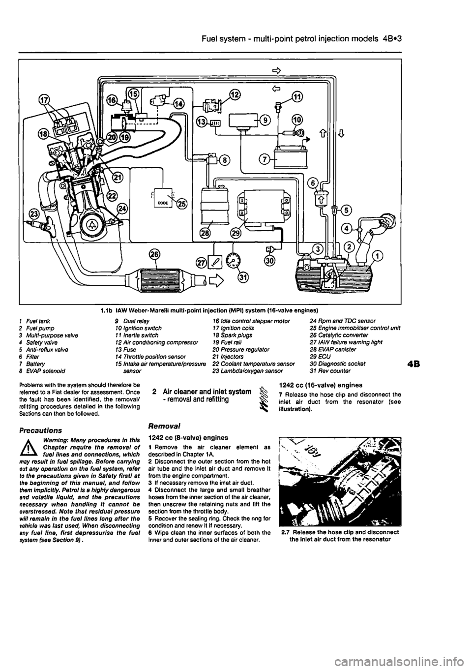
1.1b IAW Weber-Marelli multi-point injection (MPI) system (16-valve engines) J Fuel
tank
2 Fuel pump 3 Multi-purpose
valve
4 Safety
valve
5 Anti-reflux
valve
6 F/fter 7 Battery 8
EVAP
solenoid
9 Dual
relay
10 Ignition switch 111nertia switch
12
Air conditioning compressor
13
Fuse 14 Throttle position sensor
1$
idle control stepper motor 17 Ignition coils 18 Sparkplugs 19 Fuel
rail
20 Pressure regulator 21 Injectors
15
Intake air temperature/pressure 22 Coolant temperature sensor sensor 23 Lambda/oxygen sensor
24 Rpm and TDC sensor 25 Engine immobiliser control unit 26 Catalytic converter 27 IAW failure warning light 28 EVAP canister 29 ECU 30 Diagnostic socket 31 Rev counter
Problems with the system should therefore be referred to a Fiat dealer for assessment. Once the fault has been Identified, the removal/ refitting procedures detailed in the following Sections can then be followed.
Precautions
A
Warning: Many procedures In this Chapter require the removal of fuel lines and connections, which may result In fuel spillage. Before carrying out any operation on the fuel system, refer to the precautions given In Safety flrstl at the beginning of this manual, and follow them implicitly. Petrol Is a highly dangerous and volatile liquid, and the precautions necessary when handling it cannot be overstressed. Note that residual pressure will remain in the fuel lines long after the vehicle was last used, When disconnecting tny fuel line, first depressurise the fuel system {see Section 9).
2 Air cleaner and inlet system Sk - removal
and
refitting ^
Removal
1242 cc (8-valve) engines 1 Remove the air cleaner element as described In Chapter 1A. 2 Disconnect the outer section from the hot air tube and the Inlet air duct and remove it from the engine compartment. 3 If necessary remove the inlet air duct. 4 Disconnect the large and small breather hoses from the inner section of the air cleaner, then unscrew the retaining nuts and lift the section from the throttle body. 5 Recover the sealing ring. Check the nng for condition and renew it it necessary. 6 Wipe clean the inner surfaces of both the Inner and outer sections of the air cleaner,
1242 cc (16-valve) engines 7 Release the hose clip and disconnect the inlet air duct from the resonator (see illustration).
2.7 Release the hose clip and disconnect the inlet air duct from the resonator
Page 144 of 225
4D«1
Chapter 4 Part D:
Exhaust and emission control systems
Contents
Catalytic converter - general Information and precautions 7 Crankcase emission system • general information 3 Evaporative loss emission control system • information and component renewal 2
Degrees of difficulty
Exhaust manifold - removal and refitting 5 Exhaust system - general information and component renewal .... 6 General information 1 Lambda oxygen sensor - removal and refitting 4
Easy, suitable
tor novice with fittie ^
1 experience
Fairly easy, suitable for beginner with ^ some experience ^
Fairiy dfficult, lb suitable for competent ^ DIY mechanic ^
Difficult, suitable for experienced DIY ^ mechanic
Very difficult, ^ suitable far expert DIY or professional
Specifications
Torque wrench settings Exhaust down pipe to manifold Exhaust manifold Exhaust system mounting Exhaust to catalytic converter: M8 M10x1.25
Nm Ibfft 24 18 24 18 27 20
24 18 40 30 53 39
1 General information
Emission control systems All petrol engine models use unleaded petrol and are controlled by engine management systems that are 'tuned' to give the best compromise between driveability. luel consumption and exhaust emission production. In addition, a number of systems are fitted that help to minimise other harmful emissions: a crankcase emission-control system (petrol models only) that reduces the release of pollutants from the crankcase, an evaporative loss emission control system (petrol models only) to reduce the release of hydrocarbons from the fuel tank, a catalytic converter (petrol and diesel models) to reduce exhaust gas pollutants, and an Exhaust Gas Recirculation (EGR) system (turbo diesel models only) to reduce exhaust emissions. Crankcase emission control To reduce the emission of unburned hydrocarbons from the crankcase Into the atmosphere, the engine is sealed and the blow-by gases and oil vapour are drawn from inside the crankcase, through a flame trap.
into the inlet tract to be burned by the engine during normal combustion. Under conditions of high manifold depression (idling, deceleration) the gases will by sucked positively out of the crankcase. Under conditions of low manifold depression (acceleration, full-throttle running) ihe gases are forced out of the crankcase by the (relatively) higher crankcase pressure: if the engine is worn, the raised crankcase pressure (due to increased blow-by) will cause some of the flow to return under all manifold conditions. Exhaust emission control -petrol models To minimise the amount of pollutants which escape Into the atmosphere, a catalytic converter is fitted In the exhaust system. The fuel system is of the closed-loop type, in which a Lambda (or oxygen) sensor In the exhaust system provides the engine management system ECU with constant feedback, enabling the ECU to adjust the air/fuel mixture to optimise combustion. The Lambda sensor has a heating element built-in that Is controlled by the ECU through the Lambda sensor relay to quickly bring the sensor's tip to Its optimum operating temperature. The sensor's tip Is sensitive to oxygen and relays a voltage signal to the ECU
that varies according on the amount of oxygen In the exhaust gas. If the inlet air/fuel mixture is too rich, the exhaust gases are low in oxygen so the sensor sends a low-voltage signal, the voltage rising as the mixture weakens and the amount of oxygen rises In the exhaust gases. Peak conversion efficiency of all major pollutants occurs if the inlet air/fuel mixture Is maintained at the chemlcally-con*ect ratio for the complete combustion of petrol of 14.7 parts (by weight) of air to
1
part of fuel (the stoichiometric ratio). The sensor output voltage alters in a large step at this point, the ECU using the signal change as a reference point and correcting the Inlet air/fuel mixture accordingly by altering the fuel Injector pulse width. Exhaust emission control -diesel models An oxidation catalyst is fitted in the exhaust system of all diesel engine models. This has the effect of removing a large proportion of the gaseous hydrocarbons, carbon monoxide and particulates present in the exhaust gas. An Exhaust Gas Recirculation (EGR) system Is fitted to all turbo diesel engine models. This reduces the level of nitrogen oxides produced during combustion by Introducing a proportion of the exhaust gas back into the inlet manifold, under certain engine operating
Page 145 of 225
4D*2 Exhaust and emission control systems
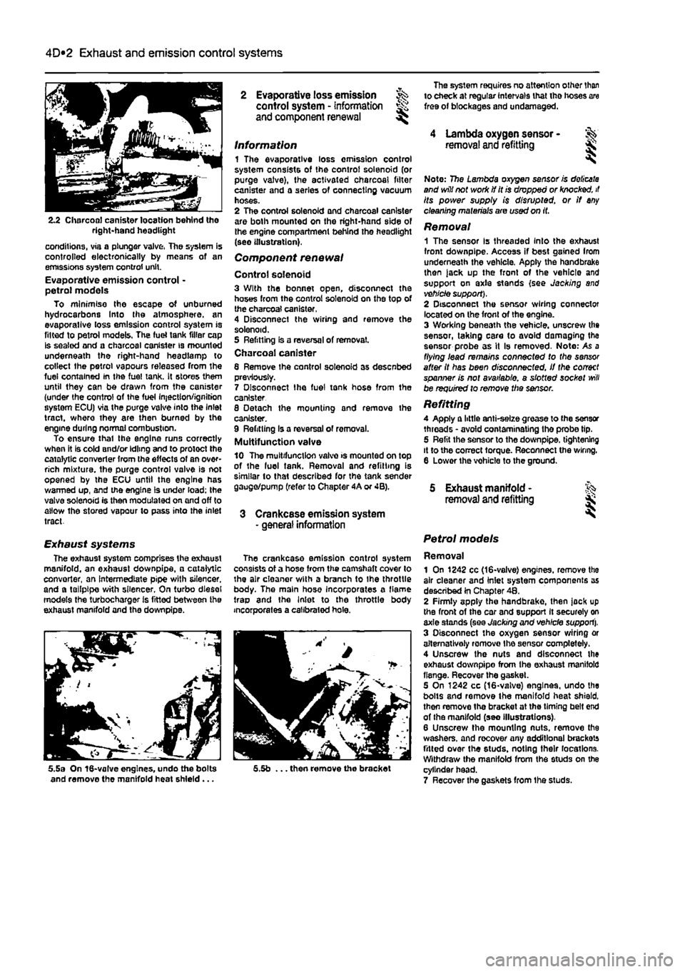
2.2 Charcoal canister location behind tho right-hand headlight
conditions, via a plunger valve, The system is controlled electronically by means of an emissions system control unit. Evaporative emission control • petrol models To minimise the escape of unburned hydrocarbons Into the atmosphere, an evaporallve loss emission control system is fitted to petrol models, The fuel tank filler cap Is sealed and a charcoal canister is mounted underneath the right-hand headlamp to collect the petrol vapours released from the fuel contained In the fuel tank. It stores them until they can be drawn from the canister (under the control of the fuel Injection/ignition system ECU) via the purge valve into the Inlet tract, where they are then burned by the engine during normal combustion. To ensure thai the engine runs correctly when it is cold and/or idling and to protect the catalytic converter from the effects of an over-rich mixture, the purge control valve is not opened by the ECU until the engine has warmed up, and the engine is under load; the valve solenoid is then modulated on and off to allow the stored vapour to pass into the inlet tract.
Exhaust systems The exhaust system comprises the exhaust manifold, an exhaust downpipe, • catalytic convorter, an intermediate pipe with silencer, and a tailpipe with silencer, On turbo diesel models the turbocharger is fitted between ihe exhaust manifold and the downpipe.
5.5a On 16-valve engines, undo the bolts and remove the manifold heat shield...
2 Evaporative loss emission ^ control system - information and component renewal ^
Information 1 The evaporative loss omission control system consists of the control solenoid (or purge valve), the activated charcoal filter canister and a series of connecting vacuum hoses. 2 The control solenoid and charcoal canister are both mounted on the right-hand side of the engine compartment behind the headlight (see illustration).
Component renewal
Control solenoid 3 With the bonnet open, disconnect the hoses from the control solenoid on the top of the charcoal canister. 4 Disconnect the wiring and remove the solenoid. 5 Refitting is a reversal of removal. Charcoal canister 6 Remove Ihe control solenoid as desenbed previously. 7 Disconnect Ihe fuel tonk hose from the canister 8 Detach the mounting and remove the canister. 9 Refitting Is a reversal of removal. Multifunction valve 10 The multifunction valve >s mounted on top of the luel tank. Removal and refitting is similar to that described for the tank sender gauge/pump (refer to Chapter 4A or 4B).
3 Crankcase emission system - general information
The crankcase emission control system consists of a hose from the camshaft cover to the air cloanor with a branch to Ihe throttle body. The main hose Incorporates a flame trap and the Inlet to the throttle body incorporates a calibrated hole.
5.5b ... then remove the bracket
The system requires no attention other than to check at regular intervals that tho hoses are free of blockages and undamaged.
4 Lambda oxygen sensor -removal and refitting &
Note: 7?5e Lambda oxygen sensor is doiicata and will not work if it is dropped or knocked, it its power supply is disrupted, or if any cleaning materials are used on it.
Removal 1 The sensor Is threaded Into the exhaust front downpipe. Access if best gained Irom underneath the vehicle. Apply the handbrake then )ack up the front of the vehicle and support on axle stands (see Jacking and vehicle support). 2 Disconnect the sensor wiring connector located on the front of the engine. 3 Working beneath the vehicle, unscrew the sensor, taking care to avoid damaging the sensor probe as it Is removed- Note: As a flying lead remains connected to the sensor after it has been disconnected, if the correct spanner is not available, a slotted socket
will
be required to remove the sensor.
Refitting A Apply a little anti-selze grease to (he sensor threads • avoid contaminating the probe tip. 5 Refit the sensor to the downpipe. tightening it to the correct torque. Reconnect the wiring. 6 Lower the vohicle to the ground.
5 Exhaust manifold - % removal and refitting jk
Petrol models
Removal 1 On 1242 cc (16-valve) engines, remove tho air cleaner and inlet system components as described in Chapter 48. 2 Firmly apply the handbrake, then jock up the front of the car and support It securely on axle stands (see Jacking and vehicle support). 3 Disconnect the oxygen sensor wiring or alternatively romovo Ihe sensor completely. 4 Unscrew the nuts and disconnect the exhaust downpipo from Ihe exhaust manifold flange. Recover the gasket. 5 On 1242 cc (16-valve) engines, undo the bolts and remove the manifold heat shield, then remove the bracket at the timing belt end of the manifold (seo Illustrations). 6 Unscrew the mounting nuts, remove the washers, and recover any additional brackets fitted over the studs, noting their locations. Withdraw the manifold from the studs on the cylinder head. 7 Recover the gaskets from Ihe studs.
Page 146 of 225
4D*3 Exhaust and emission control systems
Refitting 8 Refitting is a reversal of the removal pro-cedure but fit new gaskets. Tighten the nuts lo the specified torque.
Diesel models Note: On diesel models the inlet and exhaust
manifolds
are located on the rear of the engine
end
share the same securing nuts and gasket. Removal 8 Remove the inlet manifold as described In Part
C
of this Chapter. 10 Firmly apply the handbrake, then jack up lite front of tho car and support it securely on axle stands (see Jacking and vehicle support). 11 Straighten the tab washers (where fitted), then unscrew and remove the exhaust downpipe retaining nuts. Detach the downpipe from the manifold/turbocharger. Suitably support the downpipe. 12 Undo the manifold-to-cylinder head securing nuts and withdraw the manifold (see Illustration). 13 Separate the turbocharger from the manifold with reference to Chapter 4C. 14 Remove the gasket and clean the mating
(aces
of the manifold, cylinder head and down-pipe flange (see illustration). The gasket must
be
renewed when refitting the manifold, Refitting
15 Refitting is a reversal of the removal procedure but fit a new gasket. Tighten the retaining nuts to the specified torque and where necessary lock them by bending over
the
tocktabs.
6 Exhaust system - % general information and ^ component renewal
Genera/ Information 1 A three section exhaust system is fitted consisting of a twin-branch front downpipe, a catalytic converter, and a tailpipe with two silencers. The downpipe-to-manifold and downpipe-to-catalytic converter joints are both of flange and gasket type, whereas the remaining joint Is of the sleeve type secured
witn
a clamp ring (see illustration). 2 The system is suspended throughout its entire length by rubber mountings.
Removal 3 Each exhaust section can be removed individually or, alternatively, the complete system can be removed as a unit. Where separation of the rear sleeve Joint is necessary, it may be more practical to remove
the
entire system rather than try and separate
the Joint
In position. 4 To remove the system or part of the system, first jack up the front of the vehicle and support on axle stands (see Jacking and nhlcle support), Alternatively position the
vehicle
over an inspection pit or on car ramps.
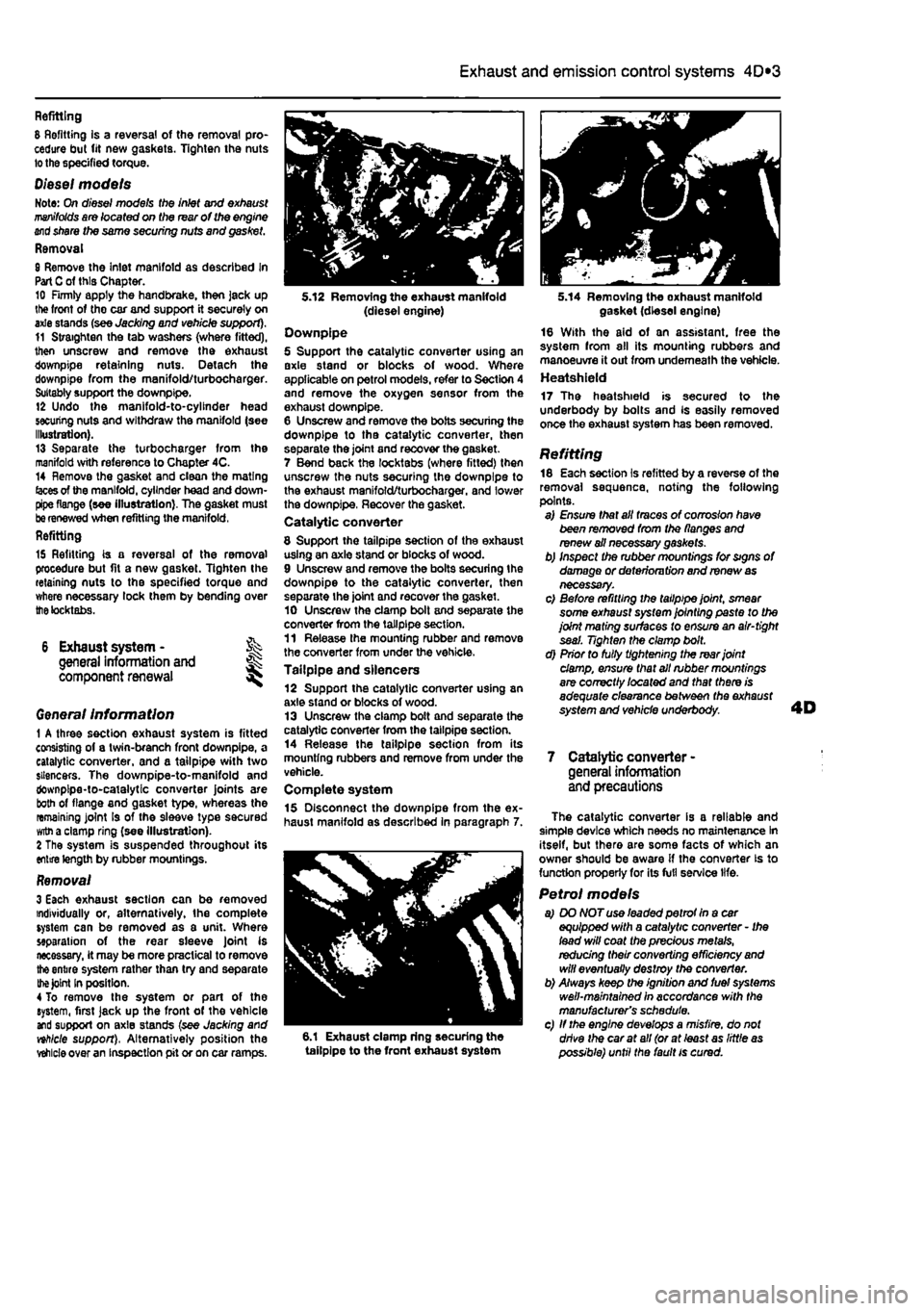
5.12 Removing the exhaust manifold (diesel engine) Downpipe 5 Support the catalytic converter using an axle stand or blocks of wood. Where applicable on petrol models, refer to Section 4 and remove the oxygen sensor from the exhaust downpipe. 6 Unscrew and remove the bolts securing the downpipe to tha catalytic converter, then separate the joint and recover the gasket. 7 Bend back the locktabs (where fitted) then unscrew the nuts securing the downpipe to the exhaust manifold/turbocharger. and lower the downpipe, Recover the gasket. Catalytic converter
8 Support the tailpipe section of the exhaust using an axle stand or blocks of wood. 9 Unscrew and remove the bolts securing the downpipe to the catalytic converter, then separate the joint and recover the gasket. 10 Unscrew the clamp bolt and separate the converter from the tailpipe section. 11 Release the mounting rubber and remove the converter from under the vehicle. Tailpipe and silencers 12 Support the catalytic converter using an axle stand or blocks of wood. 13 Unscrew the clamp bolt and separate the catalytic converter from the tailpipe section. 14 Release the tailpipe section from its mounting rubbers and remove from under the vehicle. Complete system 15 Disconnect the downpipe from the ex-haust manifold as described in paragraph 7.
6.1 Exhaust clamp ring securing the tailpipe to the front exhaust system
5.14 Removing the oxhaust manifold gasket (diesel engine) 16 With the aid of an assistant, free the system from all its mounting rubbers and manoeuvre it out from underneath the vehicle. Heatshield 17 The heatshield is secured to the underbody by bolts and Is easily removed once the exhaust system has been removed.
Refitting 18 Each section is refitted by a reverse of the removal sequence, noting the following points. a) Ensure that all traces of corrosion have been removed from the flanges and renew ail necessary gaskets. b) Inspect the rubber mountings for signs of damage or deterioru tion and renew
as
necessary. c) Before refitting the tailpipe joint, smear some exhaust system jointing paste to the joint mating surfaces to ensure an air-tight seal. Tighten the clamp bolt. d) Prior to fully tightening the rear joint damp, ensure that all rubber mountings are correctly /ocafed and that there is adequate clearance between the exhaust system and vehicle underbody.
7 Catalytic converter -general information and precautions
The catalytic converter is a reliable and simple device which needs no maintenance In itself, but there are some facts of which an owner should be aware if the converter is to function properly for its full service life.
Petrol models a) DO NOT use leaded petrot In a car equipped with a catalytic converter - Ihe lead will coat the precious metals, redudng their converting efficiency
and
will eventually destroy the converter. b) Always keep the ignition and fuel systems well-maintained in accordance with the manufacturer's schedule. c) If the engine develops a misfire, do not drive the car at all (or at least as little
as
possible) until the fault is cured.