oxygen sensor FIAT PUNTO 1994 176 / 1.G User Guide
[x] Cancel search | Manufacturer: FIAT, Model Year: 1994, Model line: PUNTO, Model: FIAT PUNTO 1994 176 / 1.GPages: 225, PDF Size: 18.54 MB
Page 145 of 225

4D*2 Exhaust and emission control systems
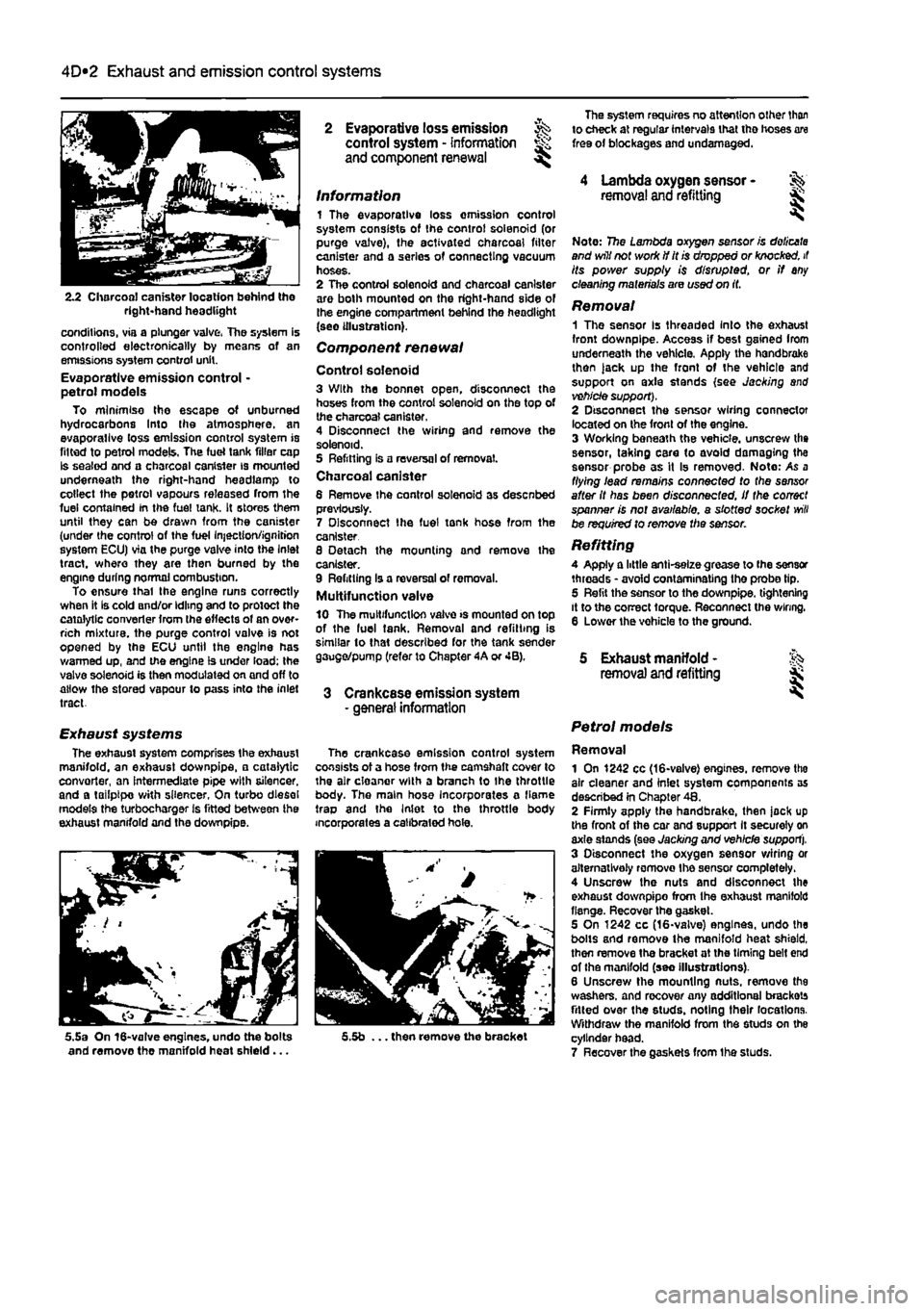
2.2 Charcoal canister location behind tho right-hand headlight
conditions, via a plunger valve, The system is controlled electronically by means of an emissions system control unit. Evaporative emission control • petrol models To minimise the escape of unburned hydrocarbons Into the atmosphere, an evaporallve loss emission control system is fitted to petrol models, The fuel tank filler cap Is sealed and a charcoal canister is mounted underneath the right-hand headlamp to collect the petrol vapours released from the fuel contained In the fuel tank. It stores them until they can be drawn from the canister (under the control of the fuel Injection/ignition system ECU) via the purge valve into the Inlet tract, where they are then burned by the engine during normal combustion. To ensure thai the engine runs correctly when it is cold and/or idling and to protect the catalytic converter from the effects of an over-rich mixture, the purge control valve is not opened by the ECU until the engine has warmed up, and the engine is under load; the valve solenoid is then modulated on and off to allow the stored vapour to pass into the inlet tract.
Exhaust systems The exhaust system comprises the exhaust manifold, an exhaust downpipe, • catalytic convorter, an intermediate pipe with silencer, and a tailpipe with silencer, On turbo diesel models the turbocharger is fitted between ihe exhaust manifold and the downpipe.
5.5a On 16-valve engines, undo the bolts and remove the manifold heat shield...
2 Evaporative loss emission ^ control system - information and component renewal ^
Information 1 The evaporative loss omission control system consists of the control solenoid (or purge valve), the activated charcoal filter canister and a series of connecting vacuum hoses. 2 The control solenoid and charcoal canister are both mounted on the right-hand side of the engine compartment behind the headlight (see illustration).
Component renewal
Control solenoid 3 With the bonnet open, disconnect the hoses from the control solenoid on the top of the charcoal canister. 4 Disconnect the wiring and remove the solenoid. 5 Refitting is a reversal of removal. Charcoal canister 6 Remove Ihe control solenoid as desenbed previously. 7 Disconnect Ihe fuel tonk hose from the canister 8 Detach the mounting and remove the canister. 9 Refitting Is a reversal of removal. Multifunction valve 10 The multifunction valve >s mounted on top of the luel tank. Removal and refitting is similar to that described for the tank sender gauge/pump (refer to Chapter 4A or 4B).
3 Crankcase emission system - general information
The crankcase emission control system consists of a hose from the camshaft cover to the air cloanor with a branch to Ihe throttle body. The main hose Incorporates a flame trap and the Inlet to the throttle body incorporates a calibrated hole.
5.5b ... then remove the bracket
The system requires no attention other than to check at regular intervals that tho hoses are free of blockages and undamaged.
4 Lambda oxygen sensor -removal and refitting &
Note: 7?5e Lambda oxygen sensor is doiicata and will not work if it is dropped or knocked, it its power supply is disrupted, or if any cleaning materials are used on it.
Removal 1 The sensor Is threaded Into the exhaust front downpipe. Access if best gained Irom underneath the vehicle. Apply the handbrake then )ack up the front of the vehicle and support on axle stands (see Jacking and vehicle support). 2 Disconnect the sensor wiring connector located on the front of the engine. 3 Working beneath the vehicle, unscrew the sensor, taking care to avoid damaging the sensor probe as it Is removed- Note: As a flying lead remains connected to the sensor after it has been disconnected, if the correct spanner is not available, a slotted socket
will
be required to remove the sensor.
Refitting A Apply a little anti-selze grease to (he sensor threads • avoid contaminating the probe tip. 5 Refit the sensor to the downpipe. tightening it to the correct torque. Reconnect the wiring. 6 Lower the vohicle to the ground.
5 Exhaust manifold - % removal and refitting jk
Petrol models
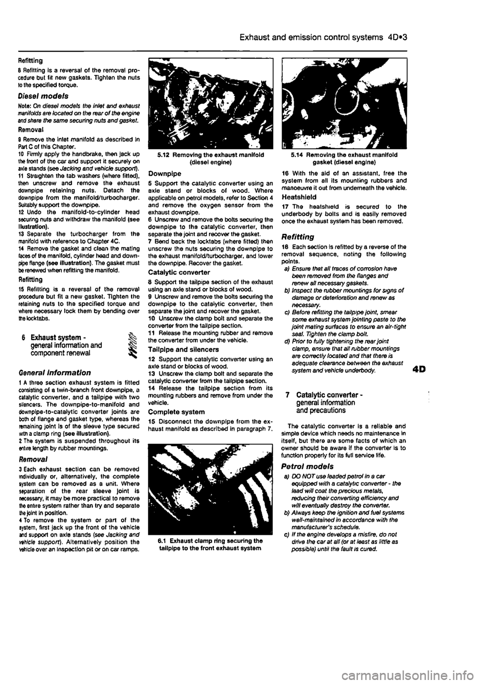
Removal 1 On 1242 cc (16-valve) engines, remove tho air cleaner and inlet system components as described in Chapter 48. 2 Firmly apply the handbrake, then jock up the front of the car and support It securely on axle stands (see Jacking and vehicle support). 3 Disconnect the oxygen sensor wiring or alternatively romovo Ihe sensor completely. 4 Unscrew the nuts and disconnect the exhaust downpipo from Ihe exhaust manifold flange. Recover the gasket. 5 On 1242 cc (16-valve) engines, undo the bolts and remove the manifold heat shield, then remove the bracket at the timing belt end of the manifold (seo Illustrations). 6 Unscrew the mounting nuts, remove the washers, and recover any additional brackets fitted over the studs, noting their locations. Withdraw the manifold from the studs on the cylinder head. 7 Recover the gaskets from Ihe studs.
Page 146 of 225

4D*3 Exhaust and emission control systems
Refitting 8 Refitting is a reversal of the removal pro-cedure but fit new gaskets. Tighten the nuts lo the specified torque.
Diesel models Note: On diesel models the inlet and exhaust
manifolds
are located on the rear of the engine
end
share the same securing nuts and gasket. Removal 8 Remove the inlet manifold as described In Part
C
of this Chapter. 10 Firmly apply the handbrake, then jack up lite front of tho car and support it securely on axle stands (see Jacking and vehicle support). 11 Straighten the tab washers (where fitted), then unscrew and remove the exhaust downpipe retaining nuts. Detach the downpipe from the manifold/turbocharger. Suitably support the downpipe. 12 Undo the manifold-to-cylinder head securing nuts and withdraw the manifold (see Illustration). 13 Separate the turbocharger from the manifold with reference to Chapter 4C. 14 Remove the gasket and clean the mating
(aces
of the manifold, cylinder head and down-pipe flange (see illustration). The gasket must
be
renewed when refitting the manifold, Refitting
15 Refitting is a reversal of the removal procedure but fit a new gasket. Tighten the retaining nuts to the specified torque and where necessary lock them by bending over
the
tocktabs.
6 Exhaust system - % general information and ^ component renewal
Genera/ Information 1 A three section exhaust system is fitted consisting of a twin-branch front downpipe, a catalytic converter, and a tailpipe with two silencers. The downpipe-to-manifold and downpipe-to-catalytic converter joints are both of flange and gasket type, whereas the remaining joint Is of the sleeve type secured
witn
a clamp ring (see illustration). 2 The system is suspended throughout its entire length by rubber mountings.
Removal 3 Each exhaust section can be removed individually or, alternatively, the complete system can be removed as a unit. Where separation of the rear sleeve Joint is necessary, it may be more practical to remove
the
entire system rather than try and separate
the Joint
In position. 4 To remove the system or part of the system, first jack up the front of the vehicle and support on axle stands (see Jacking and nhlcle support), Alternatively position the
vehicle
over an inspection pit or on car ramps.
5.12 Removing the exhaust manifold (diesel engine) Downpipe 5 Support the catalytic converter using an axle stand or blocks of wood. Where applicable on petrol models, refer to Section 4 and remove the oxygen sensor from the exhaust downpipe. 6 Unscrew and remove the bolts securing the downpipe to tha catalytic converter, then separate the joint and recover the gasket. 7 Bend back the locktabs (where fitted) then unscrew the nuts securing the downpipe to the exhaust manifold/turbocharger. and lower the downpipe, Recover the gasket. Catalytic converter
8 Support the tailpipe section of the exhaust using an axle stand or blocks of wood. 9 Unscrew and remove the bolts securing the downpipe to the catalytic converter, then separate the joint and recover the gasket. 10 Unscrew the clamp bolt and separate the converter from the tailpipe section. 11 Release the mounting rubber and remove the converter from under the vehicle. Tailpipe and silencers 12 Support the catalytic converter using an axle stand or blocks of wood. 13 Unscrew the clamp bolt and separate the catalytic converter from the tailpipe section. 14 Release the tailpipe section from its mounting rubbers and remove from under the vehicle. Complete system 15 Disconnect the downpipe from the ex-haust manifold as described in paragraph 7.
6.1 Exhaust clamp ring securing the tailpipe to the front exhaust system
5.14 Removing the oxhaust manifold gasket (diesel engine) 16 With the aid of an assistant, free the system from all its mounting rubbers and manoeuvre it out from underneath the vehicle. Heatshield 17 The heatshield is secured to the underbody by bolts and Is easily removed once the exhaust system has been removed.
Refitting 18 Each section is refitted by a reverse of the removal sequence, noting the following points. a) Ensure that all traces of corrosion have been removed from the flanges and renew ail necessary gaskets. b) Inspect the rubber mountings for signs of damage or deterioru tion and renew
as
necessary. c) Before refitting the tailpipe joint, smear some exhaust system jointing paste to the joint mating surfaces to ensure an air-tight seal. Tighten the clamp bolt. d) Prior to fully tightening the rear joint damp, ensure that all rubber mountings are correctly /ocafed and that there is adequate clearance between the exhaust system and vehicle underbody.
7 Catalytic converter -general information and precautions
The catalytic converter is a reliable and simple device which needs no maintenance In itself, but there are some facts of which an owner should be aware if the converter is to function properly for its full service life.
Petrol models a) DO NOT use leaded petrot In a car equipped with a catalytic converter - Ihe lead will coat the precious metals, redudng their converting efficiency
and
will eventually destroy the converter. b) Always keep the ignition and fuel systems well-maintained in accordance with the manufacturer's schedule. c) If the engine develops a misfire, do not drive the car at all (or at least as little
as
possible) until the fault is cured.
Page 164 of 225

Manual transmission 7A*3
3,8 Unscrew the nut and disconnect the gear selector rod from the lever on the transmission unscrew the locknut and adjusting nut from the end of the clutch cable and disconnect the cable from the transmission. Recover the damper block. On models with a hydraulically operated clutch, unscrew the mounting bolts, release the slave cylinder pushrod from the re&ase arm on the transmission, then position the cylinder to one side.
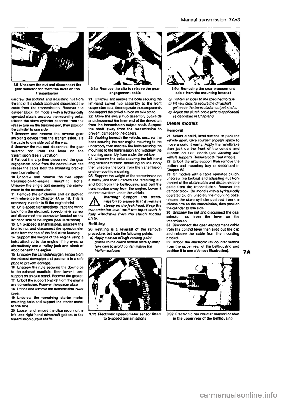
7 Unscrew and remove the reverse gear Inhibiting device from the transmission. Tie the cable to one side out of the way. 8 Unscrew the nut and disconnect the gear selector rod from the lever on the transmission (see illustration). 9 Pull out the clip then disconnect the gear engagement cable from the control lever and release the cable from the mounting bracket (see illustrations). 10 Unscrew and remove the two upper transmisslon-to-englne mounting bolts. Unscrew the single bolt securing the starter motor to the transmission. 11 Remove the air cleaner and air ducting with reference to Chapter 4A or 4B. This Is necessary In order to fit the engine hoist 12 On 5-speed transmissions, trace the wiring back from the electronic speedometer sensor and disconnect the connector located on the left-hand side of the engine (see illustration). 13 On 6-speed transmissions, unscrew the knurled nut and disconnect the speedometer cable from the top of the final drive housing. 14 Support the weight of the engine using a hoist attached to the engine lifting eyes, or alternatively use a trolley jack and block of wood beneath Ihe engine. 15 Unscrew the Lambda/oxygen sensor from the exhaust downpipe and position It In a safe place to prevent damage. 16 Unscrew the nuts securing the downpipe to the exhaust manifold, then lower It and support on an axle stand. Recover the gasket. 17 Unbolt the support bracket from the engine and transmission. Recover the spacer plate. 18 Unbolt and remove the transmission lower cover, 19 Unscrew the remaining starter motor mounting bolts and support tho starter motor to one side. 20 Loosen and remove the clips securing the left- and right-hand driveshaft gaiters to the transmission output shafts.
3.9a Remove the clip to release the gear engagement cable 21 Unscrew and remove the boils securing the left-hand swivel hub assembly to the front suspension strut, then separate the components and support the swivel hub on an axle stand. 22 Move the swivel hub assembly outwards and disconnect the inner end of the dnveshaft from the transmission output shaft. Support the shaft away from the transmission to prevent damage to the garters. 23 Working beneath the vehicle, unscrew the botts securing the rear engine mounting to the underbody then unscrew the bolts securing the mounting to the transmission and withdraw the mounting assembly from under the vehicle. 24 Unscrew the bolts securing the left-hand engine/transmission mounting to Ihe body then unscrew the bolts from the transmission and remove the mounting. 25 Support the woight of the transmission on a trolley jack then unscrew the remaining nut and bolt from the belihousing and pull the transmission away from the engine. Lower it and remove from under the vehicle. A Warning: Support the trans-mission to ensure that it remains steady on the jack head. Keep the transmission levet until the Input shaft Is fully withdrawn from the clutch friction plate. Refitting
26 Refitting is a reversal of the removal procedure, but note the following points. a) Apply a smear of high-melting-point grease to the clutch friction plate splines; take care to avoid contaminating the friction surfaces.
3.12 Electronic speedometer sensor fitted to 5-speed transmissions
3.9b Removing the gear engagement cable from the mounting bracket b) Tighten all bolts to Ihe specified torque. c) Fit new clips to secure the driveshaft gaiters to the transmission output shafts. d) Adjust the clutch cable (where applicable) as described In Chapter 6.
Diesel models
Removal 27 Seloct a solid, level surface to park the vehicle upon. Give yourself enough space to move around it easily. Apply the handbrake then jack up the front of tho vehicle and support on axlo stands (see Jacking and vehicle support). Remove both front wheels. 28 Unbolt the relay support then remove the batlery and mounting tray as described in Chapter 5A. 29 On models with a cable operated clutch, unscrew the locknut and adjusting nut from the end of the clutch cable and disconnect the cable from the transmission. Recover the damper block. On models with a hydraulically operated clutch, unscrew the mounting botts. release the slave cylinder pushrod from the release arm on the transmission, then position the cylinder to one side, 30 Unscrew the nut and disconnect the gear selector rod from the lever on the transmission. 31 Disconnect the gear engagement cable from the control lever then slide out the clip and release the cable from the mounting bracket. 32 Unbolt the electronic rev counter sensor from the upper rear of the belihousing and position it to one side (see illustration).
3.32 Electronic rev counter sensor located in the upper rear of the belihousing
Page 169 of 225

7B*4 Automatic transmission
2 Automatic transmission - ^ removal and refitting St
Removal 1 Select a solid, level surface to park the vehicle upon. Give yourself enough space to move around it easily. Apply the handbrake then jack up the front of the vehicle and support on axle stands (see Jacking and vehicle support). Remove both front wheels, 2 Remove the battery and mounting tray as described In Chapter 5A. 3 Remove the air cleaner and air inlet duct as described In Chapter 4A. 4 Disconnect the kickdown cable at the sector on the throttle housing and detach It from the mounting on the camshaft cover. Also release the cable from the support on the left-hand end of the cylinder head. 5 Disconnect the wiring connectors on the transmission. 6 Disconnect the fluid inlet and outlet Unas from the heat exchanger on top of the transmission. 7 Pull the fluid level dipstick from Its tube on the front of the transmission and tape over the top of the tube to prevent dirt entry. 8 Unscrew and remove the retaining pin and disconnect the speed selector cable from the top of the transmission. 9 Unscrew the upper bolt securing the starter motor to the transmission. 10 Unscrew the upper bolts securing the transmission to the engine. 11 Support the weight of the engine using a hoist attached to the engine lifting eyes, or alternatively UBO a trolley jack and block of wood beneath the engine, 12 Remove the screws and remove the front wheel arch liner from under the left-hand wheel arch. 13 Unscrew the nut securing the earth cablo to the transmission. 14 Using a punch drive out the roll pins securing both driveshafts to the final drive output shafts. 15 Unscrew and remove the bolts securing the left-hand swivel hub assembly to the front suspension strut, then separate the components and support the swivel hub on an axle stand. 16 Move the swivel hub assembly outwards and slide the inner end of the driveshaft from the splines on the transmission output shaft. Support the shaft away from the transmission to prevent damage to the gaiters. 17 Unscrew the lambdafoxygen sensor from the exhaust downpipe and position it In a safe place to prevent damage. 18 Unscrew ihe nuts securing the downpipe to Ihe exhaust manifold, then lower It and suppon on an axle stand. Recover the gasket. 19 Unscrew the knurled nut and disconnect the speedometer cable from the top of the final drive housing.
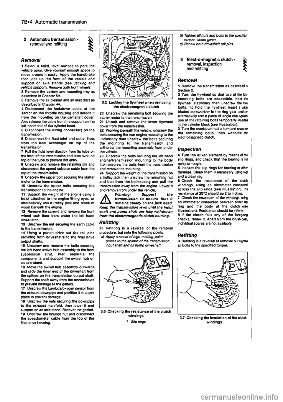
3-2 Locking the flywheel when removing the electromagnetic clutch 20 Unscrew the remaining bolt securing the staner motor to the transmission 21 Unbolt and remove Ihe lower flywheel cover from the transmission. 22 Working beneath the vehicle, unscrew the bolts securing the rear engine mounting to the underbody then unscrew the bolts securing the mounting lo the transmission and withdraw the mounting assembly from under the vehicle. 23 Unscrew the bolts securing the left-hand engine/transmission mounting to the body thon unscrew the bolts from the transmission and remove the mounting. 24 Support the weight of the transmission on a trolley jack then unscrew the remaining nut and bolt from the bellhouslng and pull the transmission away from the engine. Lower it and remove from under the vehicle.
A
Warning: Support the transmission to ensure that It remains steady on the Jack head. Keep the transmission level until the Input shaft and pump shaft are fully withdrawn from the electromagnetic clutch housing.
Refitting 25 Refitting is a reversal of the removal procedure, but note the following points. a} Apply a smear of high-melting-point grease to the splines of the transmission input shaft and oil pump driveshaft.
3.6 Checking the resistance of the clutch windings 1 Slip rings
0) Tighten all nuts and bolts to the
specified
torque, where given, c) Renew both driveshaft roll pins.
3 Electro-magnetic clutch • & removal, inspection 5. and refitting ^
Removal 1 Remove Ihe transmission as described n Section 2. 2 Turn the flywheel so that two of the lour mounting bolts are accessible, Hold tha flywheel stationary then unscrew Ihe tvrt bolts. To hold the flywheel, Insert a wida bladed screwdriver In the ring gear teeth or alternatively use a piece of angle iron against one of the retaining bolts temporarily Inserted in the cylinder block (see illustration). 3 Turn the crankshaft half a turn and unscrew the remaining bolts, then withdraw the electromagnetic clutch.
Inspection 4 Turn the driven element by means of tha slip rings, and check that the bearing is not noisy or rough. 5 Inspect the slip rings for burning or other damage. Clean them if necessary using fid and a clean rag. 6 Check the resistance of the clutch windings, using an ohmmetor connected across the slip rings (see Illustration). The resistance at 20*0 should be 2 to 4 ohms. 7 Check the Insulation of the windings, using an ohmmeter connected between either sip ring and the body of the clutch (see illustration). Resistance should be Infinity. 8 If the clutch fails any of the foregoing checks, renew it. Apart from the brush gear, Individual spares are not available.
Refitting 9 Refitting is a reversal of removal but tighten all bolts to the specified torque.
windings