Meter FIAT PUNTO 1994 176 / 1.G Repair Manual
[x] Cancel search | Manufacturer: FIAT, Model Year: 1994, Model line: PUNTO, Model: FIAT PUNTO 1994 176 / 1.GPages: 225, PDF Size: 18.54 MB
Page 181 of 225
Braking system 9®5
2 Rotate the brake disc by hand and examine the whole of the surface area swept by the brake pads, on both sides ot the disc. Note: /( will bo necessary to remove the front brake pads to allow an adequate inspection of the disc's rear surface; refer to Section 2 tor details. 3 Typically, the disc surface will have a polished appearance and should be free from heavy scoring. Smooth rippling is produced by normal operation and does not indicate excessive wear. Deep scoring and cracks, however, are indications of more serious damage in need of correction. 4 If deep scoring Is discovered, it may be possible to have the disc reground to restore the surface, depending on the extent of the damage. To determine whether this is a feasible course of action, it will be necessary to measure the thickness of the disc, as described later. 5 Check the whole surface of the disc for cracks, particularly around the roadwheel bolt holes. A cracked disc mutt be renewed. 6 A ridge of rust and brake dust at the inner and outer edges of the disc, beyond the pad contact area is normal - this can be scraped tway quite easily. 7 Raised ridges caused by the brake pads eroding the disc material, however, are an indication of excessive wear. If close examination reveals such ridges, the oiicknoss of the disc must be measured, to usess whether it is still fit for use. 8 To measure the thickness of the disc, take readings at several points on the surface using a micrometer. In the area swept by the brake pads (see Illustration). Include any points where the disc has been scored: align me Jaws of the micrometer with the deepest ares of scoring, to get a true indication of the extent of the wear. Compare these ineasurements with the limits listed in the Specifications. If the disc has worn below its minimum thickness, at any point, it must be renewed. 9 If the discs are suspected of causing brake luddor, check the disc runout, using one of
me
following methods: Runout measurement -
DTI
gauge method 10 Refit the four roadwheel bolts, together
w.1h
one M14 plain washer per stud • this will ensure adequate disc to hub contact. Tighten te studs to 5 Nm (4 Ibf ft). 11 Clamp the DTI gauge to a stand and attach the stand, preferably via a magnetic oase. to the strut mounting bracket. Align the jauge so that its pointer rests upon the area of the dtsc swept by the brake pads, on an arc i mm from the outer edge of tho disc (soe illustration). 12 Zero the gauge and slowly rotate the disc trough one revolution, observing tho pointer rcovement. Note the maximum deflection recorded and compare the figure with that >«ted In Specifications.
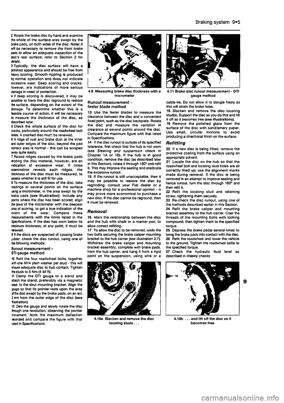
4.8 Measuring brake disc thickness with a micrometer
Runout measurement -feeler blade method 13 Use the feeler blades to measure the clearance between the disc and a convenient fixed point, such as the disc backplate. Rotate the disc and measure the variation in clearance at several points around the disc, Compare the maximum figure with that listed in Specifications. 14 If the disc runout Is outside of its specified tolerance, first check that the hub Is not worn (see Steering and suspension check in Chapter 1A or 1B). If the hub is In good condition, remove the disc (as described later in this Section), rotate it through 180° and refit it. This may improve the seating and eradicate Ihe excessive runout. 15 If the runout is still unacceptable, then It may be possible to restore the disc by regrinding; consult your Fiat dealer or a machine shop for a professional opinion - it may prove more economical to purchase a new disc. If the disc cannot be reground, then it must be renewed.
Removal 16 Mark the relationship between the disc and the hub with chalk or a marker pen, to allow correct refitting. 17 To allow the disc to be removed, undo the two bolts securing (he brake caliper mounting bracket to the hub carrier (see illustration 3.7). Withdraw the brake caliper and mounting bracket assembly, complete with brake pads, from the hub carrier, and hang it from a rigid point on the suspension, using v/lre or a
4.18a Slacken and remove the disc locating studs ...
4.11 Brake disc runout measurement - DTI gauge method
cable-tie. Oo not allow it to dangle freely as this will strain the brake hose. 18 Slacken and remove the disc locating stud(s). Support the disc as you do this and lift it off as it becomes free (see illustrations). 19 Remove the polished glaze from the surface of the disc with sand/emery paper. Use small, circular motions to avoid producing a directional finish on the surface.
Refitting 20 If a new disc Is being fitted, remove the protective coating from the surface U9ing an appropriate solvent. 21 Locate Ihe disc on ihe hub so that the roadwheel bolt and locating stud holes are all correctly lined up; use the alignment marks made during removal. If the disc is being removed in an attempt to improve seating and hence runout, turn the disc through 180° and then refit it. 22 Refit the locating stud and retaining screw, tightening them securely. 23 Re-check the disc runout, using one of the methods described earlier in this Section. 24 Refil the brake caliper and mounting bracket assembly to the hub carrier. Coat the threads of the mounting bolts with locking compound, then tighten them to the specified torque. 25 Depress the brake pedal several times to bnng the brake pads into contact with the disc. 26 Refit the roadwheel and lower the vehicle to the ground. Tighten the roadwheel bolts to the specified torque. 27 Check the hydraulic fluid level as described in Weekly checks.
4,18b ... and lift off the disc as It becomes free
Page 184 of 225
9*8 Braking system
6 Carefully examine the Inside of tho drum. Light scoring of the friction surface is normal, but if heavy scoring Is found, the drum must be renewed. 7 It is usual to find a lip on the dmm's inboard edge which consists of a mixture of rust and brake dust: this should be carefully scraped away, to leave a smooth surface which can be polished with fine (120 to 150-grade) emery paper. If, however, the tip is due to the friction surface being recessed by excessive wear, then the drum must be renewed. 6 If the drum Is thought to be excessively worn, or oval, its internal diameter must be measured at several points using an internal micrometer. Take measurements In pairs, the second at right-angles to the first, and compare the two, to check for signs of ovality. Provided that it does not enlarge the dium to beyond the specified maximum diameter, it may be possible to have the drum refinished by skimming or grinding; if this is not possible, Ihe drums on both sides must be renewed. Note that if the drum is to be skimmed, BOTH drums must be refinished. to maintain a consistent Internal diameter on both sides.
Refitting 9 II a new brake drum is to be Installed, use a suitable solvent to remove any preservative coating thai may have been applied to its internal fnction surfaces. Note that it may also be necessary to shorten the adjuster strut length, by rotating the sedated strut wheel, lo allow Ihe drum lo poss over the brake shoes • see Section S for details. 10 II tho original dfum is being refitted, align the marks made on the drum and hub before removal, then lit the drum over the hub. Refit the locating studs and tighten them to the specified torque. 11 Depress the footbrake repeatedly to expand the brake shoes against the drum, and ensure that normal pedal pressure Is restored. 12 Check and if necessary adjust the handbrake cable as described In Section 9. 13 Refit tho roadwheels, and lower the vehicle to the ground.
7 Rear wheel cylinder -removal, overhaul and refitting jS
A
Warning: Before starting work, refer to the warnings at tho beginning of Sections 2 and 11 concerning the dangers ot handling asbestos dust and hydraulic fluid.
Removal 1 Remove the brake drum fsee Section 6). 2 Remove the brake shoes (see Section 5). 3 To minimise fluid loss during the following operations, remove the master cylinder reservoir cap. then tighten it down onto a piece of polythene, lo obtain an airtight seal.
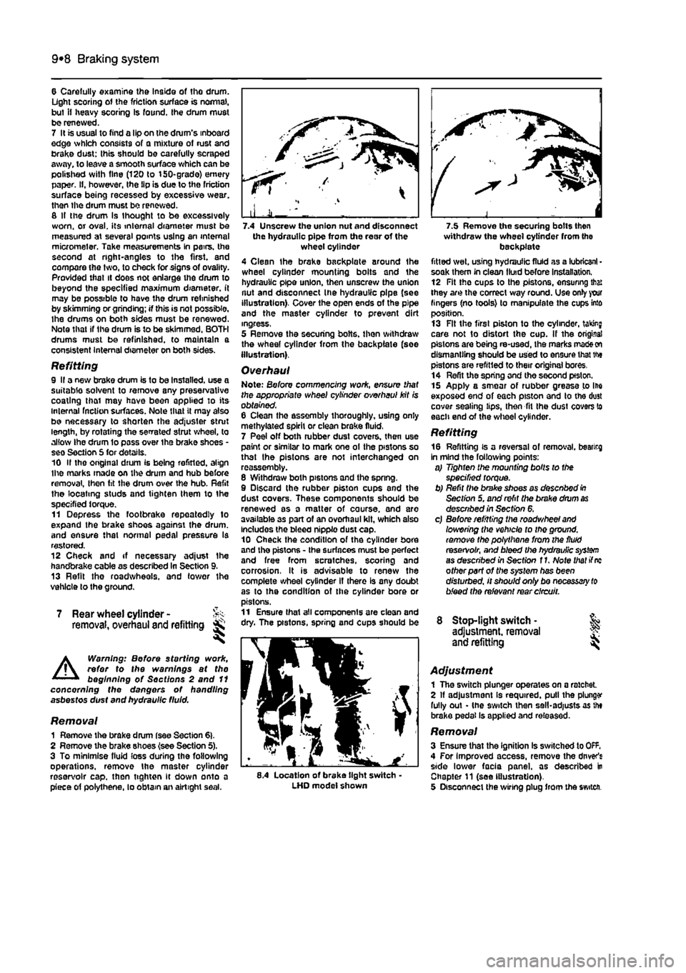
the hydraulic pipe from the rear of the wheel cylinder 4 Clean the brake backplate around Ihe wheel cylinder mounting boits and the hydraulic pipe union, then unscrew the union nut and disconnect Ihe hydraulic pipe (see illustration). Cover the open ends of the pipe and the master cylinder to prevent dirt ingress, 5 Remove the securing bolts, then withdraw the wheel cylinder from the backplate (soe Illustration).
Overhaul Note: Before commencing woric, ensure that the appropriate wheel cylinder overhaul kit is obtained. 6 Clean tho assembly thoroughly, using only methylated spirit or clean brake fluid, 7 Peel off both rubber dust covers, then use paint or similar to mark one ot the pistons so that the pistons are not interchanged on reassembly. 8 Withdraw both pistons and tho spring. 9 Discard the rubber piston cups and the dust covers. These components should be renewed as a matter of course, and are available 3s part of an overhaul kit, which also Includes the bleed nipple dust cap. 10 Check the condition of the cylinder bore and the pistons - the surfaces must be perfect and free from scratches, scoring and corrosion, It is advisable to renew the complete wheel cylinder if there is any doubt as to the condition ot the cylinder bore or pistons. 11 Ensure thai all components are clean and dry. The pistons, spring and cups should be
8.4 Location of brake tight switch-LHD model shown
withdraw the wheel cylinder from the backplate fitted wet, using hydraulic fluid as a lubricant • soak them in clean fluid before installation. 12 Fit the cups to the pistons, ensuring that they are the correct way round. Use only your fingers (no tools) to manipulate the cups into position. 13 Fit the first piston to the cylinder, taking care not to distort the cup. If the original pistons are being re-used, ihe marks
made on
dismantling should be used to ensure that the pistons are refitted to their original bores, 14 Refit the spring and the second pfston. 15 Apply a smear of rubber grease to Ihe exposed end of each piston and to the dust cover sealing lips, then fit Ihe dust covers to each end of the wheel cylinder.
Refitting 16 Refitting is a reversal of removal, bearirg in mind the following points: a) Tighten the mounting bolts to the specified torque. b) Refit the brake shoes as desenbod
In
Section 5. and refit the brake drum
as
described in Section 6. c) Before refitting the roadwheel
and
lowering the vehicle to the ground, remove the polythene from the fluid reservoir, and bleed the hydraulic
system
as described in Section f
1.
Note that if
nc
other part of the system has been disturbed, it should only bo necessary
to
bleed the relevant rear circuit.
8 Stop-light switch • & adjustment, removal J? and refitting
Adjustment 1 The switch plunger operates on a ratchet 2 If adjustment Is required, pull the plunge fully out - (he 9witch then sell-adjusts as the brake pedal Is applied and released.
Removal 3 Ensure that the ignition Is switched to OfF. 4 For Improved access, remove the driver's side lower facia panel, as described in Chapter 11 (see Illustration). 5 Disconnect the wiring plug from the switch.
Page 214 of 225
10*1
Chapter 12
Body electrical systems
Contents
Bulbs (exterior lights) - renewal 4 Bulbs (interior lights) - renewal 5 Electrical fault finding - general information 2 Exterior light units - removal and refitting 6 Fuses and relays - general Information 3 General information and precautions 1 Headlight beam alignment • general Information 6 Horn • removal and refitting 9 Instrument panel - removal and refitting 7 Loudspeakers - removal and refitting 10
Degrees of difficulty
Radio aerial - removal and refitting 11 Radio/cassette player • removal and refitting 12 Speedometer drive cable - removal and refitting 13 Switches - removal end refitting 14 Tailgate wiper motor - removal and refitting 15 Windscreen wiper motor - removal and refitting 17 Windscreen/tailgate washer system components • removal and refitting 16 Wiper arm • removal and refitting 18
Easy,
statable for ^
novice with liffle
|| experience ^
Fairly
easy,
suitable for beginner with ^ some experience ^
Fabtycffficiit,
suitable
for competent ^
DIY
mechanic ^
Difficult, suitable for
^ experienced DIY JR mechanic
Very difficult,
A,
suitable
for
expert DIY
Sj or professional ^
Specifications
Bulb ratings Watts Headlights 60/55 Front long range driving light 55 Front fogllght 55 Front direction Indicator light 21 Front sidelight 5 Front direction indicator repeater light 5 Stop light 21 Tall light 5 Rear direction indicator light 21 Reversing light 21 near fogllght 21 Hear number plate light 5 Courtesy light 10 Map reading light 5
1 Genera! information and precautions
A
Warning: fie/Ore carrying out any work on the electrical system, read through the precautions given in Safety first! at the beginning of this manual, and in Chapter 8. The electrical system is of 12-volt negative earth type. Power for the lights and all electrical accessories is supplied by a lead/acid type battery, which is charged by the alternator. This Chapter covers repair and service procedures for the various electrical components not associated with the engine. Information on the battery, alternator and starter motor can be found in Chapter 5. It should be noted that, prior to working on any component In the electrical system, the
battery negative terminal should first be disconnected, to prevent the possibility of electrical short-circuits and/or fires. Caution: Before proceeding, refer to Disconnecting the battery In the Reference Section of this manual for further information.
2 Electrical fault finding-general information
Note: Refer to the precautions given In Safety first! and in Section 1 of this Chapter before starting work. The following tests relate to testing ot the main electrical circuits, and should not be used to test delicate electronic circuits (such as antHock braking systems), particularly where an electronic con fro/ module is used.
General 1 A typical electrical circuit consists of an electrical component, any switches, relays, motors, fuses, fusible links or circuit breakers related to that component, and the wiring and connectors which link the component to both the battery and the chassis. To help to pinpoint a problem in an electrical circuit, wiring diagrams are Included at the end of this manual. 2 Before attempting to diagnose an electrical fault, first study the appropriate wiring diagram, to obtain a more complete understanding of the components included In the particular circuit concerned. The possible sources of a fault can be narrowed down by noting whether other components related to the circuit are operating properly. If several components or circuits fait at one time, the problem Is likely to be related to a shared fuse or earth connection.
Page 215 of 225
12*2 Body electrical systems
3 Electrical problems usually stem from simple causes, such as loose or corroded connections, a faulty earth connection, a blown fuse, a melted lusible link, or a fautty relay {refer to Section 3 for details of testing relays). Visually inspect the condition of all (uses, wires and connections in a problem circuit before testing the components. Use the wiring diagrams lo determine which terminal connections will need to be checked, in order to pinpoint the trouble-spot. 4 The basic tools required for electrical fault-finding include a circuit tester or voltmeter (a 12-volt bulb with a set of lest leads can also be used for certain tests}; a self-powered test light (sometimes known as a continuity tester); an ohmmeter (to measure resistance): a battery and set of tesi leads: and a lumper wire, preferably with u circuit breaker or fuse incorporated, which can be used to bypass susoect wires or electrical components. Before attempting to locate a problem with tost instruments, use the wiring diagram to determine where to make the connections. 5 To find the source of an intermittent wiring fault (usually due to a poor or dirty connection, or damaged wiring Insulation), a wiggle test can be performed on the wiring. This involves wiggling the wiring by hand, to see if tha fault occurs as the wiring Is moved. It should be possible to narrow down the source of the fault to a particular section of wiring. This method of testing can be used in conjunction with any of the tests descnbed in the following sub-Sections. 6 Apart from problems due to poor connections, two basic types of fault can occur in an electrical circuit - open-circuit, or short-circuit. 7 Open-circuit faults are caused by a break somewhere in the circuit, which prevents current from flowing. An open-circuit fault will prevent a component from working, but will not cause the relevant circuit fuse to blow 8 Short-circuit faults are caused by a shod somewhere in the circuit, which allows Die current flowing In the circuit to escape along an alternative route, usually to earth. Short-circuit faults are normally caused by a breakdown in wiring insulation, which allows a feed wire to touch either another wire, or an earthed component such as the bodysheli. A short-circuit fault will normally cause the relevant circuit fuse to blow.
Finding an open-circuit 9 To check for an opon-circuit, connect one lead of a circuit tester or voltmoter to either the negative battery terminal or a known good earth. 10 Connect the other lead to a connector in the circuit being tested, preferably nearest to the batter/ or luse. 11 Switch on the circuit, bearing In mind that some circuits are live only when tho ignition switch is moved to a particular position. 12 If voltage is present (Indicated either by
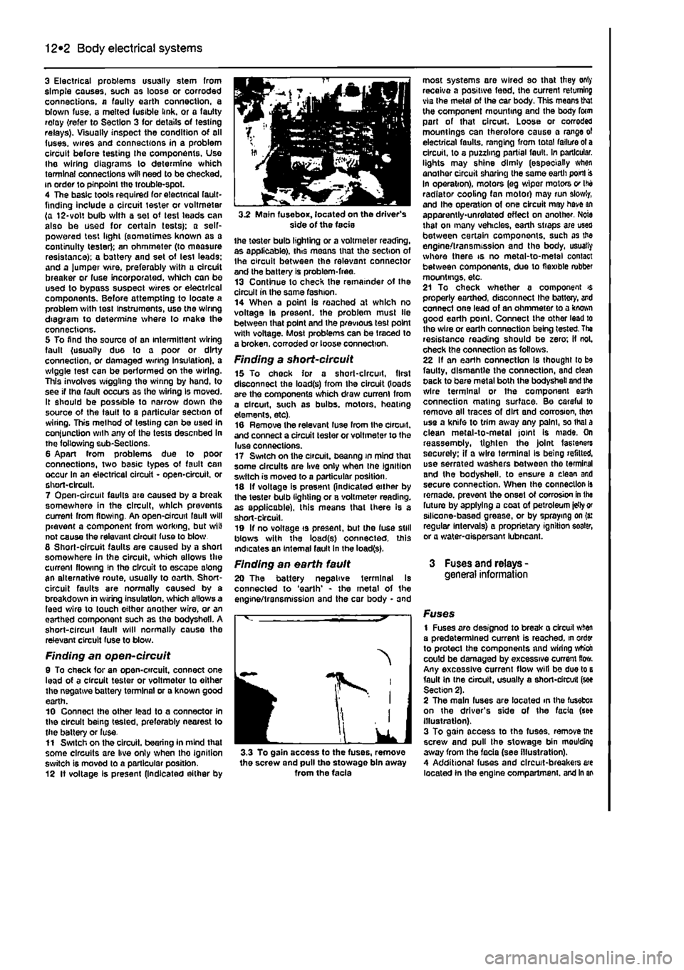
3.2 Main fuse box, located on the driver's side of the facie the toster bulb lighting or a voltmeter reading, as applicable), this means that tho section of Ihe circuit between the relevant connector and the battery is problem-free. 13 Continue to check the remainder ot the circuit in the same fashion. 14 When a point is reached at which no voltage Is present, the problem must lie between that point and the previous test point with voltage. Most problems can be traced to a broken, corroded or loose connection.
Finding a short-circuit 15 To check for a short-circuit, first disconnect the load(s) from the circuit (loads are the components which draw current from a circuit, such as bulbs, motors, heating elements, etc). 16 Remove the relevant luse Irom the circuit, and connect a circuit tester or voltmeter to the luse connections. 17 Switch on the circuit, beanng in mind that some circuits are live only when the ignition switch is moved to a particular position. 18 If voltage is present (indicated either by the tester bulb lighting or a voltmeter reading, as applicable), this means that there Is a short-circuit. 19 If no voltage is present, but the fuse still blows with the load(s) connected, this indicates an internal fault in the load(s).
Finding an earth fault 20 The battery negative terminal Is connected to 'earth' - the metal of the engine/transmission and the car body - and
I
IK
J 3.3 To gain access to the fuses, remove the screw and pull the stowage bin away from the facia
most systems are wired so that they only receive a positive feed, the current returning via the metal of Ihe car body. This means that the component mounting and the body form part of that circuit. Loose or corroded mountings can therefore cause a range of electrical faults, ranging from total failure ot a circuit, to a puzzling partial fault. In particular, lights may shine dimly (especially when another circuit sharing the same earth port In operation), motors (eg wiper motors v Ihe radiator cooling fan motor) may run slowly, and Ihe operation of one circuit may have an apparently-unrelated effect on another. Ncie that on many vehicles, earth straps axe uses between certain components, such as the engine/transmission and the body, usually whore there is no metal-to-metal contact between components, due to flexible rubber mountings, etc. 21 To check whether a component $ properly earthed, disconnect Ihe battery, and connect one lead of an ohmmeter to a kwwi good earth point. Connect the other lead to the wire or earth connection being tested. Tha resistance reading should be zero; if not. check the connection as follows. 22 If an earth connection Is thought to be faulty, dismantle the connection, and clean pack to bare metal both the bodysheli and ite wire terminal or the component earth connection mating surface. Be careful to remove all traces of dirt and corrosion, then use a knife to trim away any palm, so thai a clean metal-to-metal joint Is mads. On reassemoly, tighten the joint fasteners securely: if a wire terminal Is being refitted, use serrated washers between tho terminal and the bodysheli. to ensure a clean and secure connection. When the connection is remade, prevent the onset ot corrosion in the future by applying a coat of petroleum idly
or
stlicone-based grease, or by spraying on (a: regular intervals} a proprietary ignition eoater, or a water-aispersant lubneant.
3 Fuses and relays -general information
Fuses 1 Fuses are designod to break a circuit when a predetermined current is reached, in order to protect the components and wiring wttioh could be damaged by excessive current How. Any excessive current flow will be due to a fault in the circuit, usually a short-circuit (see Section 2). 2 The main fuses are located in the fusefcox on the driver's side of the facia (see illustration). 3 To gain access to the fuses, remove tne screw and pull the stowage bin moulding away from the facia (see illustration). 4 Additional fuses and circuit-breakers are located In the engine compartment, and in an
Page 221 of 225
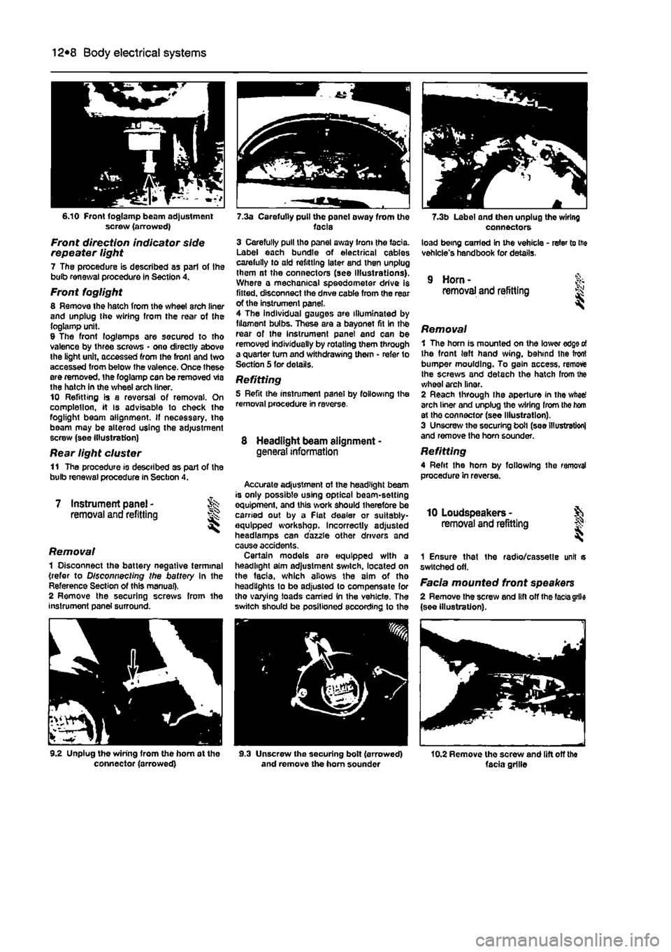
12*8 Body electrical systems
6.10 Front foglamp beam adjustment screw (arrowed)
Front direction indicator side repeater light 7 The procedure is described as pari of the bulb renewal procedure In Section 4.
Front foglight 8 Remove the hatch from the wheel arch liner and unplug Ihe wiring Irom the rear of the foglamp unit. 9 The front foglamps are secured to tho valence by three screws • one directly above the light unit, accessed from the front and two accessed Irom below the valence. Once these ere removed, the foglamp can be removed via the hatch in the wheel arch liner. 10 Refitting is a reversal of removal. On complellon, it Is advisable to check the foglight beam alignment. If necessary, the beam may be altered using the adjustment screw (see Illustration)
Rear light cluster 11 The procedure is described as part of the bulb renewal procedure in Section 4.
7 Instrument panel -removal and refitting
Removal 1 Disconnect the battery negative terminal (refer to Disconnecting the battery in the Reference Section of this manual). 2 Remove the securing screws from 1he instrument panel surround.
9.2 Unplug the wiring from the hom at tho connector (arrowed)
7.3a Carefully pull the panel oway from the facia 3 Carefully pull tho panel away from (he facia. Label each bundle of electrical cables carefully to old refitting later end then unplug them nt the connectors (see illustrations). Where a mechanical speedometer drive is fitted, disconnect the dnve coble from the rear of the instrument panel, 4 The individual gauges are Illuminated by filament bulbs. These are a bayonet fit In the rear of the Instrument panel and can be removed individually by rotating them through a quarter turn and withdrawing them • refer to Section 5 for details.
Refitting 5 Refit the instrument panel by following the removal procedure in reverse
8 Headlight beam alignment -general information
Accurate adjustment ot the headlight beam is only possible using optical beam-setting equipment, and this work should therefore be carried out by a Fiat dealer or suitably-equipped workshop. Incorrectly adjusted headlamps can dazzle other drivers and cause accidents. Certain models are equipped with a headlight aim adjustment switch, located on the facia, which allows the aim of tho headlights lo be adjusted to compensate lor tho varying loads carried in the vehicle. The switch should be positioned according to Ihe
9.3 Unscrew the securing bolt (arrowed) and remove the horn sounder
7.3b Label and then unplug the wiring connectors load being carried in the vehicle - refer to lie vehicle's handbook for details.
9 Horn -removal and refitting
Removal 1 The horn is mounted on the lower edge o! the front left hand wing, behind Ihe front bumper moulding. To gain access, remove the screws and detach the hatch from the wheel arch linor. 2 Reach through the aperture in the wheel arch liner and unplug the wiring Irom the hom st the connector (see Illustration). 3 Unscrew the securing boll (see Illustration) and remove the horn sounder.
Refitting 4 Refit the hom by following the removal procedure in reverse.
10 Loudspeakers -removal and refitting §;
1 Ensure that the radio/cassette unit is switched off.
Facia mounted front speakers 2 Remove the screw and lift off the
facia
grfle (see illustration).
10.2 Remove tho screw and lift off the facia grille
Page 222 of 225
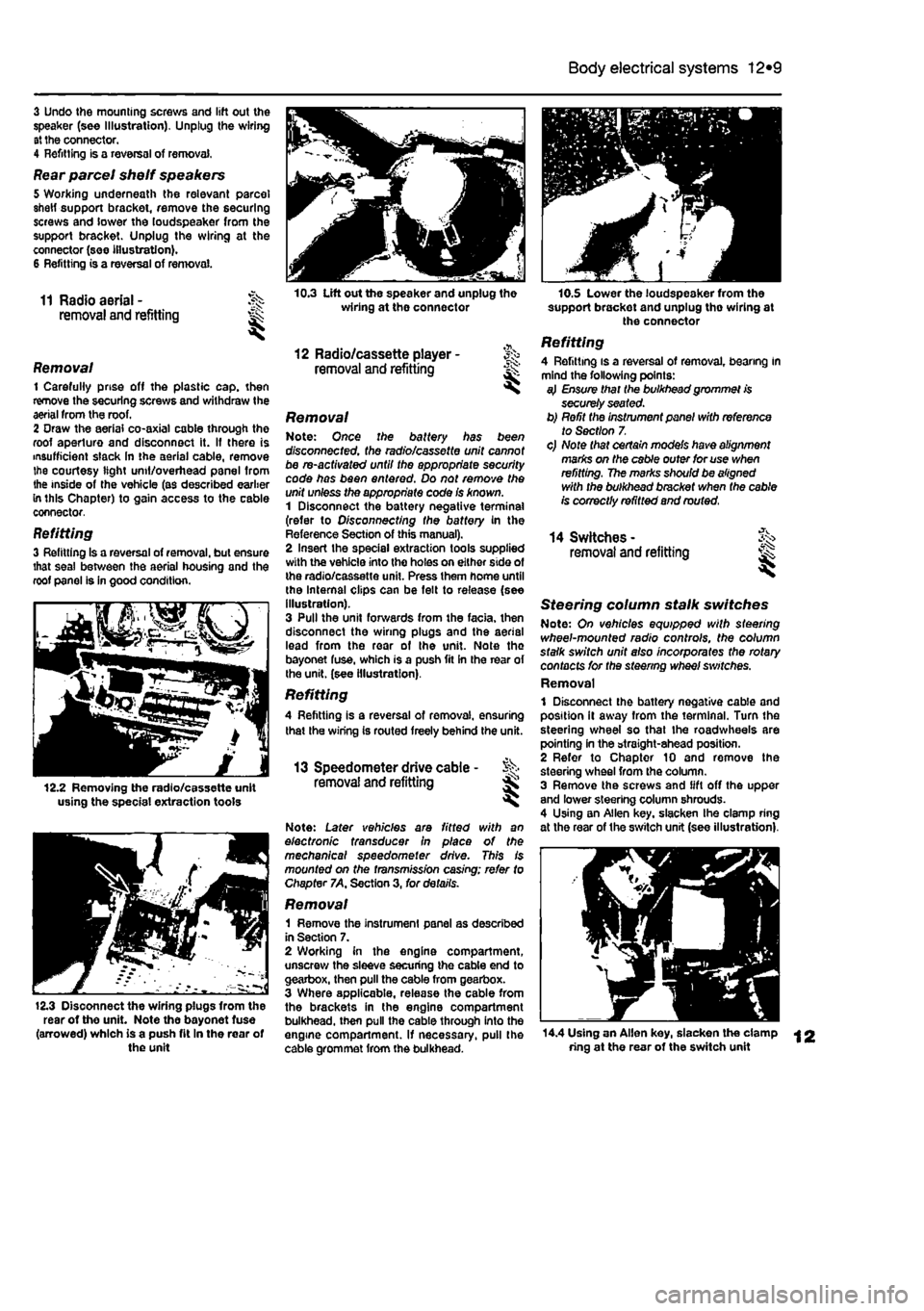
Body electrical systems 12*9
3 Undo the mounting screws and lift out the speaker (see Illustration). Unplug the wiring at the connector. 4 Refitting is a reversal of removal,
Rear parcel shelf speakers 5 Working underneath the relevant parcel shetf support bracket, remove the securing screws and lower the loudspeaker from the support bracket. Unplug the wiring at the connector (see illustration). 6 Refitting is a reversal of removal.
11 Radio aerial - J^s removal and refitting ^
Removal 1 Carefully prise off the plastic cap. then remove the securing screws and withdraw the aerial from the roof. 2 Oraw the aerial co-axial cable through the roof aperture and disconnect it. If there is insufficient slack In the aerial cable, remove the courtesy light unit/overhead panel from the inside of the vehicle (as described earlier in this Chapter) to gain access to the cable connector,
Refitting 3 Refitting Is a reversal of removal, but ensure that seal between the aerial housing and the roof panel is in good condition.
12.2 Removing the radio/cassette unit using the special extraction tools
12.3 Disoonnect the wiring plugs from the rear of the unit. Note the bayonet fuse (arrowed) which is a push fit In the rear of the unit
10.3 Lift out the speaker and unplug the wiring at the connector
12 Radio/cassette player -removal and refitting ^
Removal Note: Once the battery has been disconnected, the radio/cassette unit cannot be re-activated until the appropriate security code has been entered. Do not remove the unit unless the appropriate code Is known. 1 Disconnect the battery negative terminal (refer to Disconnecting the battery in the Reference Section of this manual). 2 Insert the special extraction tools supplied with the vehicle into the holes on either side of the radio/cassette unit. Press them home until the Internal clips can be felt to release (see illustration). 3 Pull the unit forwards from the facia, then disconnect the wiring plugs and the aerial lead from the rear of the unit. Note the bayonet fuse, which is a push fit in the rear of the unit, (see illustration).
Refitting A Refitting is a reversal of removal, ensuring that the wiring Is routed freely behind the unit.
13 Speedometer drive cable - % removal and refitting Ss ^
Note: Later vehicles are fitted with an electronic transducer in place of the mechanical speedometer drive. This is mounted on the fransm/ss/on casing; refer to Chapter 7A, Section 3, for details.
Removal 1 Remove the instrument panel as described in Section 7. 2 Working in the engine compartment, unscrew the sleeve securing the cable end to gearbox, then pull the cable from gearbox. 3 Where applicable, release the cable from the brackets in the engine compartment bulkhead, then pull the cable through into the engine compartment. If necessary, pull the cable grommet from the bulkhead.
10.S Lower the loudspeaker from the support brackot and unplug tho wiring at the connector
Refitting 4 Refitting is a reversal of removal, bearing in mind the following points: a} Ensure that the bulkhead grommet is securely seated. b) Refit the instrument panel with reference to Section 7. c) Note that certain models have alignment marks on the cable outer for use when refitting. The marks should be aligned with the bulkhead bracket when the cable is correctly refitted and routed.
14 Switches -removal and refitting ^
Steering column stalk switches Note: On vehicles equipped with sfeezing wheel-mounted radio controls, the column stalk switch unit also incorporates the rotary contacts for the steering wheel switches. Removal 1 Disconnect the battery negative cable and position it away from the terminal. Turn the steering wheel so that the roadwheeis are pointing in the straight-ahead position. 2 Refer to Chapter 10 and remove the steering wheel from the column. 3 Remove the screws and lift off the upper and lower steering column shrouds. 4 Using an Allen key. slacken Ihe clamp ring at the rear of the switch unit (see illustration),
14.4 Using an Allen key, slacken the clamp ring at the rear of the switch unit