Overhaul FIAT PUNTO 1994 176 / 1.G Repair Manual
[x] Cancel search | Manufacturer: FIAT, Model Year: 1994, Model line: PUNTO, Model: FIAT PUNTO 1994 176 / 1.GPages: 225, PDF Size: 18.54 MB
Page 192 of 225

Suspension and steering 10*4
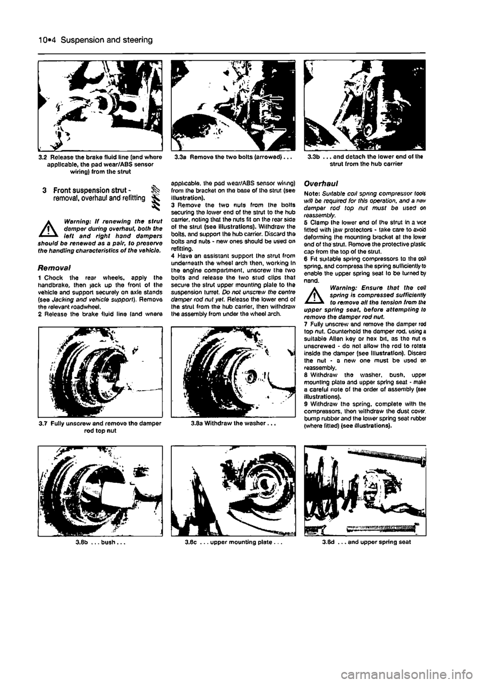
3.2 Release the brake fluid line (and where applicable, the pad wear/ABS sensor wiring) from the strut
3 Front suspension strut -removal, overhaul and refitting *
A
Warning: If renewing the Strut damper during overhaul both the left and right hand dampers should be renewed as a pair, to preserve the handling characteristics of the vehicle.
Removal 1 Chock the resr wheels, apply the handbrake, then jack up the fronl of the vehicle and support securely on axle stands (see Jacking and vehicle support). Remove the relevant roadwheel. 2 Release the brake fluid line (and wnere
3.3a Remove the two bolts (arrowed)...
applicable, the pad wear/ABS sensor wiring) from Ihe bracket on the base of the strut (see illustration). 3 Remove the two nuts from Ihe bolts securing the lower end of the strut to the hub carrier, noting that the nuls fit on the rear side of the strut (see illustrations). Withdraw the bolts, and support the hub carrier. Discard the bolts and nuts • new ones should be used on refitting. 4 Have an assistant support the strut from underneath the wheel arch then, working In the engine compartment, unscrew the two bolts and release the two stud clips that secure the strut upper mounting plate to the suspension turret. Do not unscrew the centre damper rod nut yet. Release the lower end ol the strut from the hub carrier, then withdraw the assembly from under the wheel arch.
3.7 Fully unsorew and remove tho damper rod top nut 3.3a Withdraw the washer.
3.3b ... and detach the lower end of the strut from the hub carrier
Overhaul Note: Suitable coil spring compressor fools will be required for this operation, and a
new
damper rod top nut must be used on reassembly. 5 Clamp Ihe lower end of Ihe strut in a vice fitted with jaw protectors - take care to avois deforming the mounting bracket at the lower end of the strut. Remove the protective plastic cap from the top of the strut. 6 Fit suitable spring compressors to the coil spring, and compress Ihe spring sutllciently to enable the upper spring seat to be turned by nand.
A
Warning: Ensure that the coil spring Is compressed sufficiently to remove all the tension from
tha
upper spring seat, before attempting to remove the damper rod nut. 7 Fully unscrew and remove the damper rod top nut. Countorhofd the domper rod. using
a
suitable Allen key or hex bit. as tho nut * unscrewed • do not allow the rod to rotate inside the damper (see Illustration). Discard the nut • a new one must be used on reassembly. 8 Withdraw tho washer, bush, upper mounting plate and upper spring seat • make a careful note of the order of assembly (see illustrations). 9 Withdraw the spring, complete with the compressors, thon v/ithdraw the dust cover, bump rubber and Ihe lower spring seat rubber (where fitted) (see illustrations).
Page 195 of 225

Suspension and steering
10*195
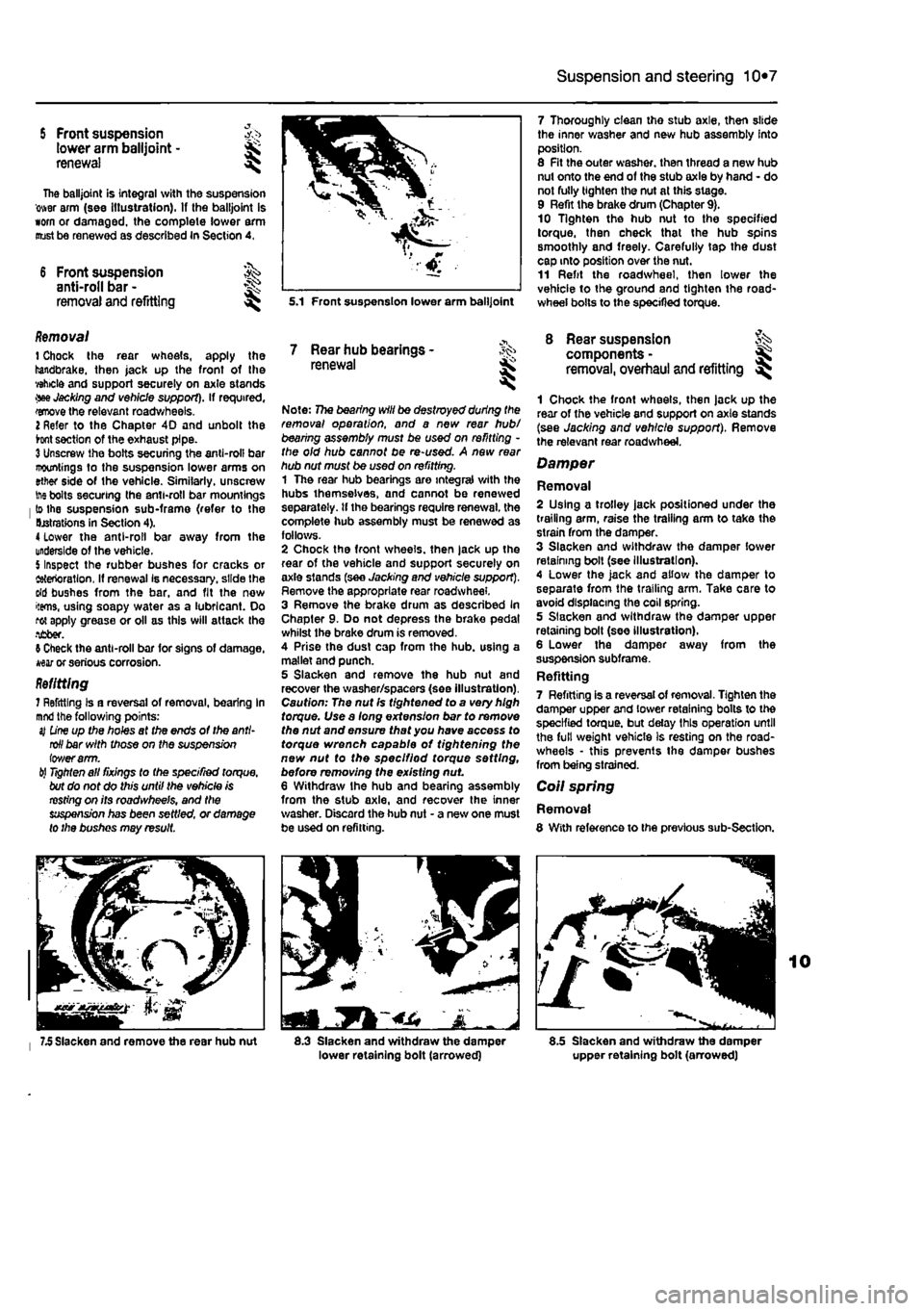
5 Front suspension >,•> tower arm balljoint -renewal ^
The balljoint is integral with the suspension ower arm (see Illustration). If the balljoint is worn or damaged, the complete lower arm oust be renewed as described In Section 4.
6 Front suspension ^ anti-roll bar -
removal and refitting s^
Removal 1 Chock the rear wheels, apply the handbrake, then jack up the front of the vehicle and support securely on axle stands •we Jacking and vehicle support). If required, wove the relevant roadwheels. 2 Refer to the Chapter 4D and unbolt the hnt section of the exhaust pipe. 3 Unscrew the bolts securing the anti-roll bar mountings to the suspension lower arms on ether side of the vehicle. Similarly, unscrew
ine
bolts securing the anti-roll bar mountings lo the suspension sub-frame (refer to the Derations in Section 4). 4 lower the anti-roll bar away from the underside of the vehicle. 5 Inspect the rubber bushes for cracks or ietertoratlon, If renewal Is necessary, slide the dd bushes from the bar, and fit the now items, using soapy water as a lubricant. Do rot apply grease or oil as this will attack the •ifiber. 9 Check the anti-roll bar for signs of damage, war or serious corrosion. Refitting 7 Refitting Is a reversal of removal, bearing In
mnd
the following points: sj
D'rw
up the holes af the ends of the anti-roll bar with those on the suspension iov/erarm. til
Tighten
all fixings to the specified torque, but do not do this until the vehicle is resting on its roadwheels, and the suspension has been settled, or damage to the bushes may result.
7.5 Slacken and remove the rear hub nut
5.1 Front suspension lower arm balljoint
7 Rear hub bearings -renewal
Note: 77ie bearing will be destroyed during the removal operation, and a new rear hub/ bearing assembly must be used on refitting -the old hub cannot be re-used. A new rear hub nut must be used on refitting. 1 The rear hub bearings are integral with the hubs themselves, and cannot be renewed separately, tf the bearings require renewal, the complete hub assembly must be renewed as follows. 2 Chock the front wheels, then jack up the rear of the vehicle and support securely on axle slands (see Jacking and vehicle support). Remove the appropriate rear roadwheel. 3 Remove the brake drum as described In Chapter 9. Do not depress the brake pedal whilst the brake drum is removed. 4 Prise the dust cap from the hub. using a mallet and punch. 5 Slacken and remove the hub nut and recover the washer/spacers (see illustration). Caution: The nut Is tightened to a very high torque. Use a long extension bar to remove the nut and ensure that you have access to torque wrench capable of tightening the new nut to the speclfiod torque setting, before removing the existing nut 6 Withdraw Ihe hub and bearing assembly from the stub axle, and recover the inner washer. Discard the hub nut - a new one must be used on refitting.
1
8.3 Slacken and withdraw the damper lower retaining bolt (arrowed)
7 Thoroughly clean tho stub axle, then slide the inner washer and new hub assembly into position. 8 Fit the outer washer, then thread a new hub nut onto the end of the stub axle by hand - do not fully tighten the nut at this stage. 9 Refit the brake drum (Chapter 9). 10 Tighten the hub nut to the specified torque, then check that the hub spins smoothly and freely. Carefully tap the dust cap into position over the nut. 11 Refit the roadwheel, then lower the vehicle to the ground and tighten the road-wheel bolts to the specified torque.
8 Rear suspension components -removal, overhaul and refitting ^
1 Chock the front wheels, then jack up the rear of the vehicle and support on axle stands (see Jacking and vehicle support). Remove the relevant rear roadwheel.
Damper
Removal 2 Using a trolley jack positioned under the trailing arm, raise the trailing arm to take the strain from the damper. 3 Slacken and withdraw the damper lower retaining boll (see Illustration). 4 Lower the jack and allow the damper to separate from the trailing arm. Take care to avoid displacing the coil spring. 5 Slacken and withdraw the damper upper retaining bolt (see illustration). 6 Lower the damper away from the suspension subframe. Refitting 7 Refitting is a reversal of removal. Tighten the damper upper and lower retaining bolts to the specified torque, but delay this operation until the full weight vehicle is resting on the road-wheels • this prevents the damper bushes from being strained.
Coil spring
Removal 8 With reference to the previous sub-Section.
8.5 Slacken and withdraw the damper upper retaining bolt (arrowed)
Page 197 of 225

Suspension and steering 10*9
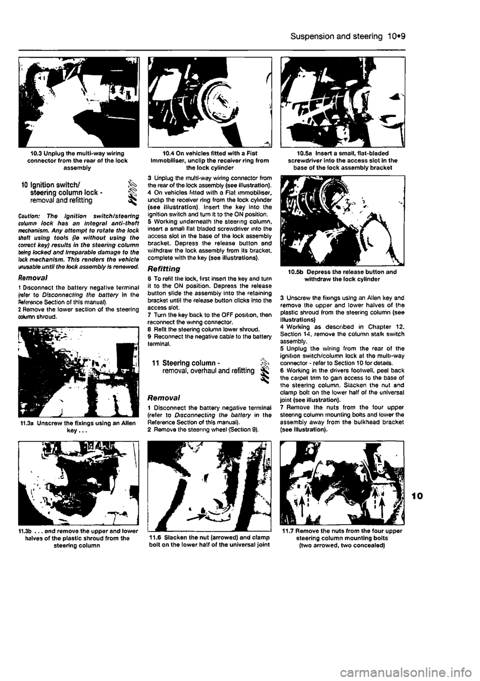
10.3 Unplug the multi-way wiring connector from the rear of tho lock assembly
10 Ignition switch/ steering column lock • ^ removal and refitting ^
Caul/on: The Ignition switch/steering column lock has on integral and-tho ft mechanism. Any attempt to rofafe tho lock shaft using tools (lo without using the correct key) results in the steering column tebg locked and Irreparable damage to the lock mechanism. This renders the vehicle
unusable
until tho lock assembly Is renewed.
Removal 1 Disconnect the battery negative terminal (refer to Disconnecting the battery In the Reference Section of this manual}. 2 Remove the lower section of the steering column shroud.
11.3a Unscrew the fixings using an Allen key...
f
10.4 On vehicles fitted with a Flat Immobiliser, uncllp the receiver ring from the lock cylinder 3 Unplug the multi-way wiring connector from the rear of the lock assembly (see illustration). 4 On vehicles fitted with a Fiat immobiliser. uncltp the receiver ring from the lock cylinder (see illustration). Insert the key Into the ignition switch and turn it to the ON position. 5 Working underneath the steering column, insert a small fiat bladed screwdriver into the access slot in the base of the lock assembly bracket. Depress Ihe release button and withdraw the lock assembly from Its bracket, complete with the key (see illustrations).
Refitting 6 To refit the lock, first inserl the hey and turn it to the ON position. Depress the release button slide the assembly into the retaining bracket until the release button clicks Into the access slot. 7 Turn the key back to the OFF position, then reconnect the wmng connector. 8 Relit the steering column lower shroud. 9 Reconnect the negative cable to the battery terminal.
11 Steering column - ^ removal, overhaul and refitting jK
Removal 1 Disconnect the battery negative terminal (refer to Disconnecting the battery in the Reference Section of this manual). 2 Remove the steenng wheel (Section 9).
10.5a Insert a small, flat-bladed screwdriver into the access slot in the base of the lock assembly bracket
10.5b Depress tho release button and withdraw the lock cylinder
3 Unscrew the fixings using an Allen key and remove the upper and lower halves of the plastic shroud from the steering column (see illustrations) 4 Working as described in Chapter 12. Section 14. remove the column stalk switch assembly, 5 Unplug the wiring from the rear of the ignition switch/column lock at the multi-way connector • refer to Section 10 for details. 6 Working in the drivers footweli. peel back the carpet trim to gam access to the base of the steering column. Slacken the nut and clamp bolt on the lower half of the universal joint (see illustration). 7 Remove Ihe nuts from the four upper steenng column mounting bolts and lower the assembly away from the bulkhead bracket (see illustration).
11.7 Remove the nuts from the four upper steering column mounting bolts (two arrowed, two concealed)
11.3b ... end remove the upper and lower halves of the plastic shroud from the 11-6 Slacken the nut (arrowed) and clamp steering column bolt on the lower half of the universal joint
Page 198 of 225

10*10 Suspension and steering
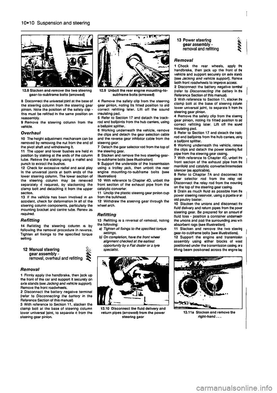
12.8 Slacken and remove the two steering goar-to-subirame bolts (arrowed) 8 Disconnect the universal joint at the base of the steering column from the steering gear pinion. Note the position of tho safety clip • this must be refitted In the same position on reassembly. 9 Remove Ihe steering column from the vehicle.
Overhaul 10 The hoight adjustment mechanism can be removed by removing the nut from the end of the pivot shaft and withdrawing it. 11 The upper and lower bushes are held in position by staking at the ends of the column tube. Relieve the staking using a mallet and punch to extract the bushes. 12 Check for excessive radial and axial play In the universal joints at both ends of the lower steering column. The lower section of the steering column may be renewed separately if required, by slackening the clamp bolt and detaching It from the upper section. 13 If the vehicle has been Involved in an accident, check for deformation In all ol the steering column components, particularly the mounting bracket and centre tube. Renew as required.
Refitting 14 Refitting the steering column is by following the removal procedure in reverse. Tighten all fixings to Ihe specified torque setting.
12 ManuaJ steering fk gear assembly -removal, overhaul and refitting
Removal 1 Firmly apply the handbrake, then jack up the front of the car and support it securely on axie stands (see Jacking and vehicle support). Remove the front road wheels. 2 Disconnect the battery negative terminal (refer to Disconnecting the battery in the Reference Section of this manual). 3 With reference to Section 11. slacken the clamp boil at the base of steering column lower universal |o!nt, to separate it rrom the steering gear pinion.
12.9 Unbolt the rear engine mountlng-to-subframe bolts (arrowed) 4 Remove the safety clip from the steering gear pinion, noting Its fitted position to aid correct refitting later. Lift off the sound insulating pad. 5 Refer to Section 17 and dotach the track* rod end bailjoints from the hub carriers, using a balljoint splitter. 6 Working underneath the vehicle, remove the clips and detach the gear selection cable and the reverse gear inhibitor cable from the steenng gear. 7 Delach the gear selector rod from the top of the steering gear, 8 Slacken and remove the two steering gear-to-subframe bolts (see Illustration) 9 Support the underside of the transmission using a trolley jack, then unbolt the rear engine mountlng-to-subframe bolts (see illustration) 10 With reference to Chapter 4D. unbolt the front section of the exhaust pipe from the catalytic converter. 11 Unclip the plastic steenng gear pinion cup from ihe bulkhead. 12 Withdraw the steenng gear through the wheel arch.
Refitting 13 Refitting is a reversal of removal, noting the following: a) Tighten all fixings lo the specified torque settings. b) On completion, have the front wheel alignment checked at the earliest opportunity by a Fiat dealer or a tyro specialist.
13.10 Disconnect the fluid delivery and return pipes (arrowed) from the power steering gear
13 Power steering * gear assembly - J removal and refitting ^
Removal 1 Chock the rear wheels, apply tN handbrake, then jack up the front ot thi vehicle and support securely on axle standi (see Jacking and vehicle support). Remove both front roadwheels to improve access. 2 Disconnect the battery negative terminal (refer to Disconnecting the battery In tto Reference Section of this manual). 3 With reforence to Section 11, slacken ihe clamp bolt at the base of steering cohimn lower universal joint, to separate ll from Ihe steering gear pinion. 4 Remove the safety clip from the steenng gear pinion, noting its fitted position lo aid correct refitting later. Lift off the sound Insulating pad. 5 Refer to Section 17 and detach the track-rod end bailjoints from the hub carriers, usty a balljoint splitter. 6 Working underneath the vehicle, ranwvi the clips and detach the power steering fluid pipe from the steering gear casing. 7 With reference to Chapter 40, unboil lbs front section of the exhaust pipe from the manifold and catalytic converter/intermediate silencer (as applicable). 8 Refer to Chaptor 7A and disconnect the gear selector rod from the relay rod Disconnect the relay rod from the mounting on the top of the steering gear casing. 9 Drain as much fluid as possible from the power steering reservoir, using a pipette or
an
old poultry baster. 10 Slacken the unions and disconnect the fluid delivery and return pipes from the power steering gear. Be prepared for an amount
erf
fluid loss - position a container underneath the unions and pad the surrounding area wth absorbent rags (see Illustration). 11 Slacken and remove the two sleeting gear-to-subframe bolts (see illustrations). 12 Support the engine and tronsmission assembly using either blocks of wood positioned under the transmission casing,
or a
lifting beam positioned across the engine
bay
13.11a Slacken and remove the right-hand...