bar FIAT PUNTO 1994 176 / 1.G Workshop Manual
[x] Cancel search | Manufacturer: FIAT, Model Year: 1994, Model line: PUNTO, Model: FIAT PUNTO 1994 176 / 1.GPages: 225, PDF Size: 18.54 MB
Page 5 of 225
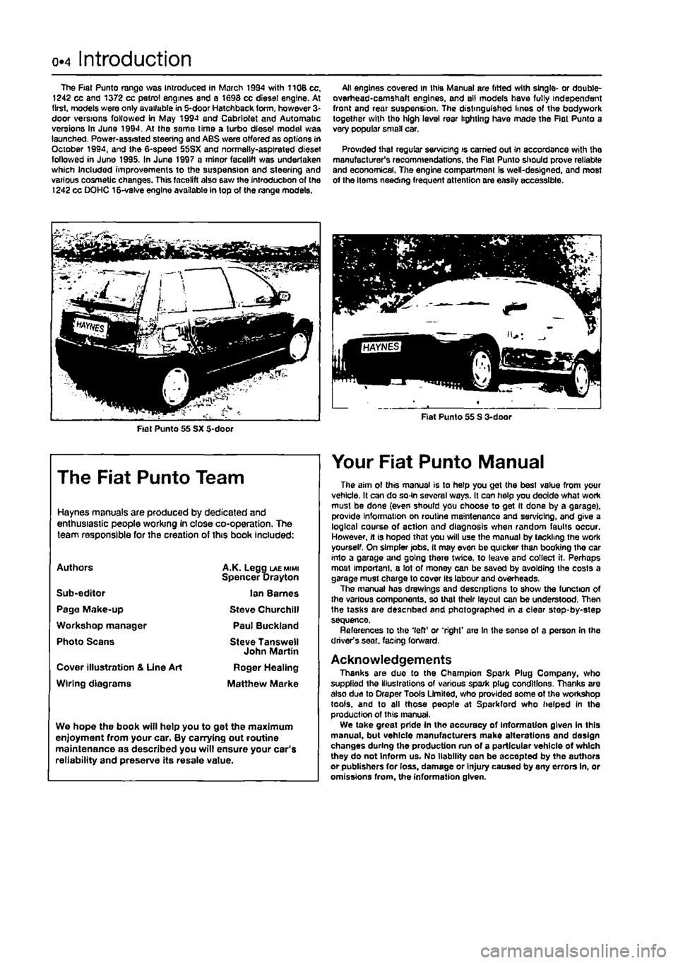
0.4 Introduction
The Fiat Punto range was Introduced in March 1994 with 1106 cc, 1242 cc and 1372 cc petrol engines and a 1698 cc diesel engine. At first, models wero only available in 5-door Hatchback form, however 3-door versions followed in May 19SM and Cabriolet and Automatic versions In June 1994. At the seme lime a lurbo diesel model was launched. Power-ass«sted steering and ABS were offered as options in October 1994, and the 6-speed 55SX and norrrally-asptraled dieset followed in June 1995. In June 1997 a minor facelift was undertaken which Included improvements to the suspension and steering and various cosmetic changes. This facelift also saw the introduction of fie ! 242 cc DOHC 1S-valve engine available In top of the range models.
Ait engines covered in this Manual are fitted with single- or double-overhead •camshaft engines, end all models have fully independent front and rear suspension. The distinguished lines of the bodywork together with tho high level rear lighting have made the Rat Punto a very popular small car.
Provided that regular servicing is earned out In accordance with tho manufacturer's recommendations, the Flat Punto should prove reliable and economical. The engine compartment is well-designed, and most of the items needing frequent attention are easily accessible.
The Fiat Punto Team
Haynes manuals are produced by dedicated and enthusiastic people working in close co-operation. The team responsible for the creation of this book included:
Authors
Sub-editor Page Make-up Workshop manager Photo Scans
Cover illustration & Une Art
Wiring diagrams
A.K. Legg laemimi
Spencer Drayton
Ian Barnes
Steve Churchill Paul Buckland
Steve Tanswell John Martin
Roger Healing
Matthew Marke
We hope the book will help you to get the maximum enjoyment from your car. By carrying out routine maintenance as described you will ensure your car's reliability and preserve its resale value.
Your Fiat Punto Manual
The aim ol this manual is to help you get the best value from your vehicle, It can do so-ln several ways. It can help you decide what worfc must be done (even should you choose to get It dons by a garage), provide information on routine maintenance and servicing, and give a logical course of action and diagnosis when random faults occur. However, it is hoped that you will use the manual by tackling the work yourself. On simpler jobs, It may even be quicker than booking tho car into a garage and going there twice, io leave and collect it. Perhaps mosl important, a lot of money can be saved by avoiding the costs a garage must charge to cover Its labour and overheads, The manual has drawings and descriptions to show the function of the various components, so that their layoul can be understood, Then the tasks are described and photographed in a clear step-by-step sequence. References to the 'left' or 'right' are In the sense of a person in the driver's seat facing forward.
Acknowledgements Thanks are duo to the Champion Spark Plug Company, who supplied the Illustrations of various spark plug conditions. Thanks are also due to Oraper Tools Limited, who provided some of the workshop tools, and to all those people at Sparkford who helped In the production of this manual. We take great pride In tho accuracy of information given In this manual, but vehicle manufacturers make alterations and design changes during the production run of a particular vehicle of which they do not Inform us. No liability oen be accepted by the authors or publishers for loss, damage or Injury caused by any errors in, or omissions from, the information given.
Page 6 of 225
Safety first! 0.5
Working on your ear can be dangerous. This page shows just some of the potential risks and hazards, with the aim of creating a safety-conscious attitude.
General hazards
Scalding • Don't remove the radiator or expansion tank cap while the engine is hot. • Engine oil, automatic transmission fluid or power steering fluid may also be dangerously hot if the engine has recently been running.
Burning • Beware of burns from the exhau3t system and from any part of the engine. Brake discs and drums can also be extremely hot immediately after use.
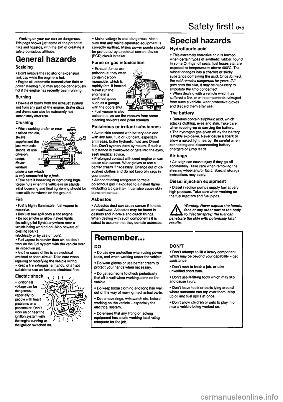
Crushing • When working under or near a raised vehicle. ~ always supplement the ' ' -jack with axle stands, or use ... drive-on i'j ramps. kr Never venture ™ under
a
car
vv/j/ch
Is only supported by a jack. • Take card if loosening or tightening high-torque nuts when the vehicle is on stands. Initial loosening and final tightening should be done with the wheels on the ground.
Fire • Fuel Is highly flammable; fuel vapour is explosive. • Don't (et fuel spill onto a hot engine. • Do not smoke or allow naked lights (including pilot lights) anywhere near a vehicle being worked on. Also beware of creating sparks (electrically or by use of toots). • Fuel vapour is heavier than air, so don't work on the fuel system with the vehicle over an inspection pit. • Another cause of fire is an electrical overload or short-circuit. Take care when repainng or modifying the vehicle wiring. • Keep a fire extinguisher handy, of a type suitable for use on fuel and electrical fires.
Electric shock x ^ ^ ? , • Ignition HT _ " voltage can be ^ dangerous, ~ especially to > people with heart problems or a pacemaker. Don't work on or near the f^ ignition system with fT") the engine running or ' J ' J the Ignition switched on.
• Mains voltage is also dangerous. Make sure that any mains-operated equipment is correctly earthed. Mains power points should be protected by a residual current device (RCD) circuit breaker.
Fume or gas intoxication • Exhaust fumes are poisonous: they often contain carbon monoxide, which is rapidly fatal if inhaled. Never run the engine in a confined space such as a garage with the doors shut, • Fuel vapour is also poisonous, as are the vapours from some cleaning solvents and paint thinners.
Poisonous or irritant substances • Avoid skin contact with battery acid and with any fuel, fluid or lubricant, especially antifreeze, brake hydraulic fluid and Diesel fuel. Don't syphon them by mouth. If such a substance is swallowed or gets into the eyes, seek medical advice. « Prolonged contact with used engine oil can cause skin cancer. Wear gloves or use a barrier cream If necessary. Change out of oll-soaked clothes and do not keep oily rags in your pocket. • Air conditioning refrigerant forms a poisonous gas if exposed to a naked flame {including a cigarette). It can also cause skin burns on contact.
Asbestos • Asbestos dust can cause cancer if inhaled or swallowed. Asbestos may be found In gaskets and in brake and clutch linings. When dealing with soch components It is safest to assume that they contain asbestos.
Special hazards
Hydrofluoric acid • This extremely corrosive acid is formed when cerlam types of synthetic rubber, found In some O-rings, oil seals, fuel hoses etc. are exposed to temperatures above 400;C. The rubber changes into a charred or sticky substance containing the acid. Once formed, the acid remains dangerous for years, tfit gets onto the skin, it may be necessary to amputate the limb concerned. • When dealing with a vehicle which has suffered a fire, or with components salvaged from such a vehicle, wear protective gloves and discard them after use.
The battery • Batteries contain sulphuric acid, which attacks clothing, eyes and skin. Take care when topping-up or carrying the battery. • The hydrogen gas given off by the battery is highly explosive. Never cause a spark or allow a naked light nearby. Be careful when connecting and disconnecting battery chargers or jump leads.
Air bags • Air bags can cause injury if they go off accidentally. Take care when removing the steenng wheel and/or facia. Special storage instructions may apply.
Diesel injection equipment • Diesel injection pumps supply fuel at very high pressure. Take care when working on the fuel injectors and fuel pipes.
A
Warning: Never expose the hands, face or any otfterpart of the body to injector spray; the fuel can penetrate the skin with potentially fatal results.
Remember...
DO • Do use eye protection when using power tools, and when working under the vehicle. • Do wear gloves or use barrier cream to protect your hands when necessary. • Do get someone to check periodically that all is well when working alone on the vehicle. • Do keep loose clothing and long hair well out of the way of moving mechanical parts. • Do remove rings, wrtstwatch etc. before working on the vehicle - especially the electrical system, • Do ensure that any lifting or jacking equipment has a safe working load rating adequate for the job.
DON'T • Don't attempt to lift a heavy component which may be beyond your capability - get assistance. • Don't rush to finish a job. or take unverified short cuts. • Don't use ill-fitting toots which may slip and cause injury. • Don't leave tools or parts lying around where someone can trip over them. Mop up oil and fuel spills at once. • Don't allow children or pets to play In or near a vehicle being worked on.
Page 24 of 225
Component location - petrol models 1A.5
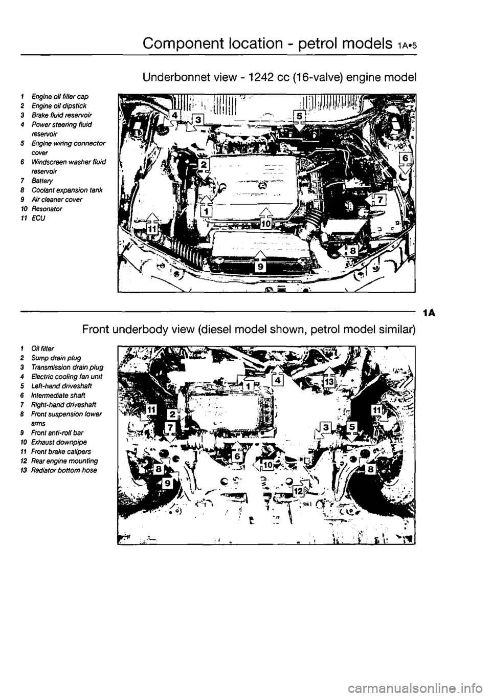
Underbonnet view - 1242 cc (16-valve) engine model
1
Engine
olt filler
cap
2
Engine
oil dipstick 3
Brake
fluid
reservoir
4
Power
steering fluid reservoir 5
Engine
wiring connector cover 6
Windscreen
washer
fluid
reservoir 7 Battery 8
Coolant
expansion
tank
9 Air cleaner
cover
10 Resonator 11 ECU
1
Oil filter
2
Sump
drain plug 3
Transmission
drain plug A
Electric
cooling Ian unit 5
Left-hand driveshaft
6
Intermediate shaft
7
Right-hand driveshaft
B
Front
suspension lower arms 9
Front
anti-roll
bar
10
Exhaust
downpipe 11
Front
brake calipers (2
Rear engine
mounting IS Radiator bottom hose
Front underbody view (diesel model shown, petrol model similar)
Page 25 of 225
ia«6 Component location - petrol models
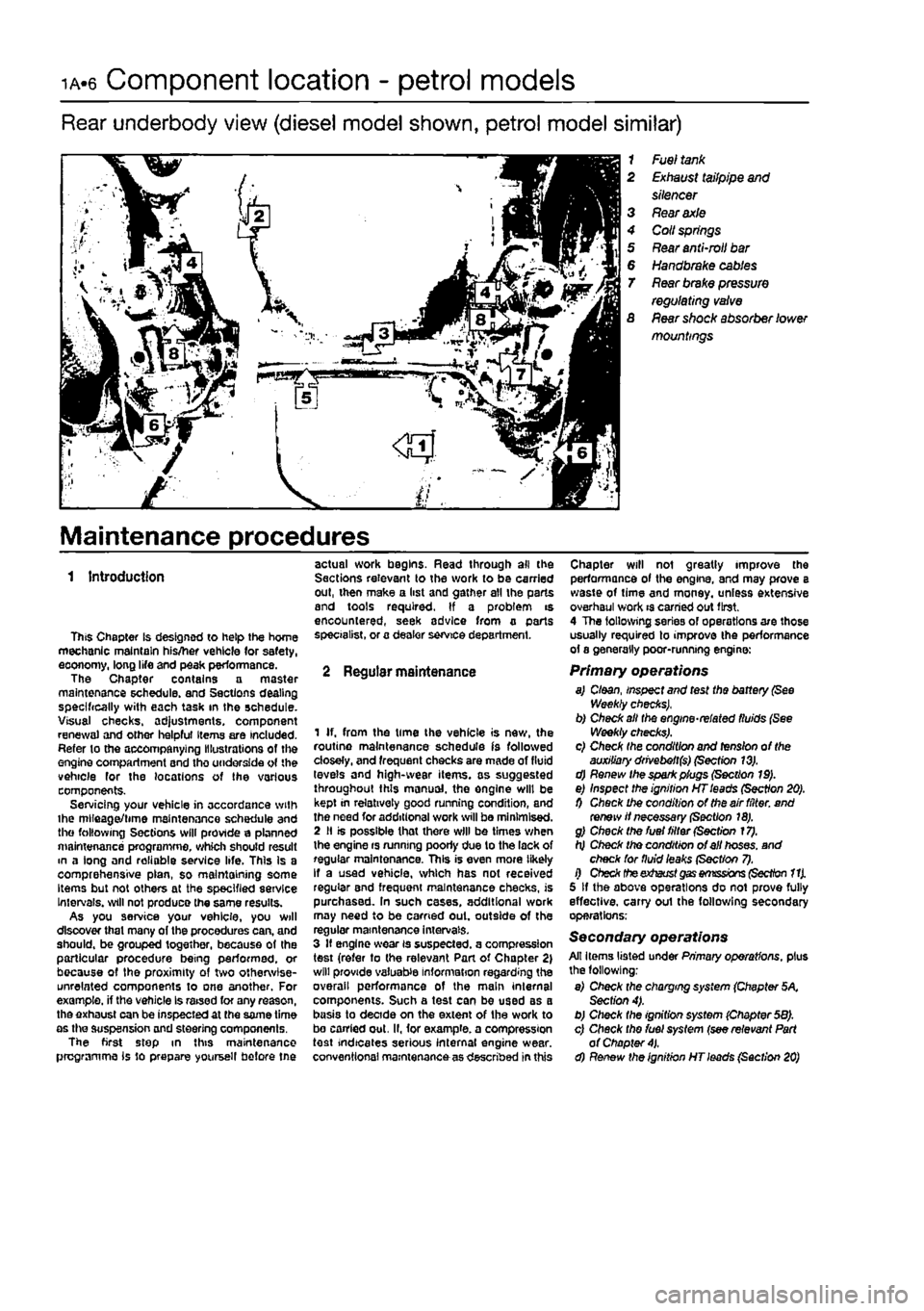
Rear underbody view (diesel model shown, petrol model similar)
1 Fuel
tank
2
Exhaust
tailpipe
and
silencer 3
Rear axle
4 Coll
springs
5
Rear
anti-mil
bar
6
Handbrake cables
T
Rear brake pressure
regulating
valve
S
Rear
shock absorber lower mountings
Maintenance procedures
1 Introduction
This Chapter is designed to help the home mechanic maintain his/her vehicle (or safety, eoonomy, long life and peak performance. The Chapter contains a master maintenance schedule, and Sections dealing specifically with each task in the schedule. Visual checks. ad}ustments, component renewal and other helpful Items are included. Refer to the accompanying Illustrations of the engine compartment and tho underside of the vehicle for the locations of the various components. Servicing your vehicle in accordance with ihe mlleaget/time maintenance schedule and the following Sections will provide a planned maintenance programme, which should result m a long and reliable service life. This Is a comprehensive plan, so maintaining some Items but not others at the specified service Intervals, will not produce the same results. As you service your vehicle, you will discover that many of the procedures can, and should, be grouped together, because of the particular procedure being performed, or because of the proximity of two otherwise-unrelated components to one another. For example, if the vehicle Is raised for any reason, the exhaust can be inspected at the same time as the suspension and steering components. The first step in this maintenance programme is to prepare yoursell before tne
actual work begins. Read through all the Sections relevant to the work to be carried out, then make a list and gather all the parts and tools required. If a problem is encountered, seek advice from a parts specialist, or a dealer service department.
2 Regular maintenance
1 If. from the time the vehicle is new, the routine maintenance schedule is followed closely, and frequent checks are made of fluid levels and high-wear items, as suggested throughout this manual, the engine will be kept in relatively good running condition, and the need for additional work will be minimised. 2 II is possible that there will be times when the engine rs running poorly due to the lack of regular maintenance. This is even more likely If a used vehicle, which has not received regular and frequent maintenance checks, is purchased. In such cases, additional work may need to be carried out. outside of the regular maintenance intervals. 3 If engine wear is suspected, a compression test (refer to the relevant Part of Chapter 2) will provide valuable information regarding the overall performance of the main internal components. Such a test can be used as a basis to decide on the extent of the work to bo carried out. II, for example, a compression test indicates serious internal engine wear, conventional maintenance as described in this
Chapter will not greatly improve the performance of the engine, and may prove a waste of time and money, unless extensive overhaul work is carried out first. 4 The following series of operations are those usually required to improve the performance of a generally poor-running engine:
Primary operations a) Cloan, inspect and test the battery
(See
Weekly checks), b) Check alt the engine-related fluids (See Weekly checks). c) Check the condition and tension of the auxiliary drivebeft($) (Section 13). d) Renew the spark plugs (Section 19). e) Inspect the ignition HT leads (Section 20). 0 Check the condition of the air filter, and renew if necessary (Section 18). g) Check the fuel filter (Section 17). h) Check tho condition of ell hoses, and check for fluid leaks (Sect/on 7). i) Check theexhaust
gas emissions (Section 11).
5 If the above operations do not prove fully effective, carry out the following secondary operations;
Secondary operations All items listed under Primary operations, plus the following; e) Check the charging system (Chapter 5K Section 4). b) Check the ignition system (Chapter 58). c) Check tho fuel system (see relevant Part of Chapter
4).
d) Renew the ignition HT leads (Section 20)
Page 28 of 225
Every 10 000 miles - petrol models ia.q
10 Pollen filter renewal
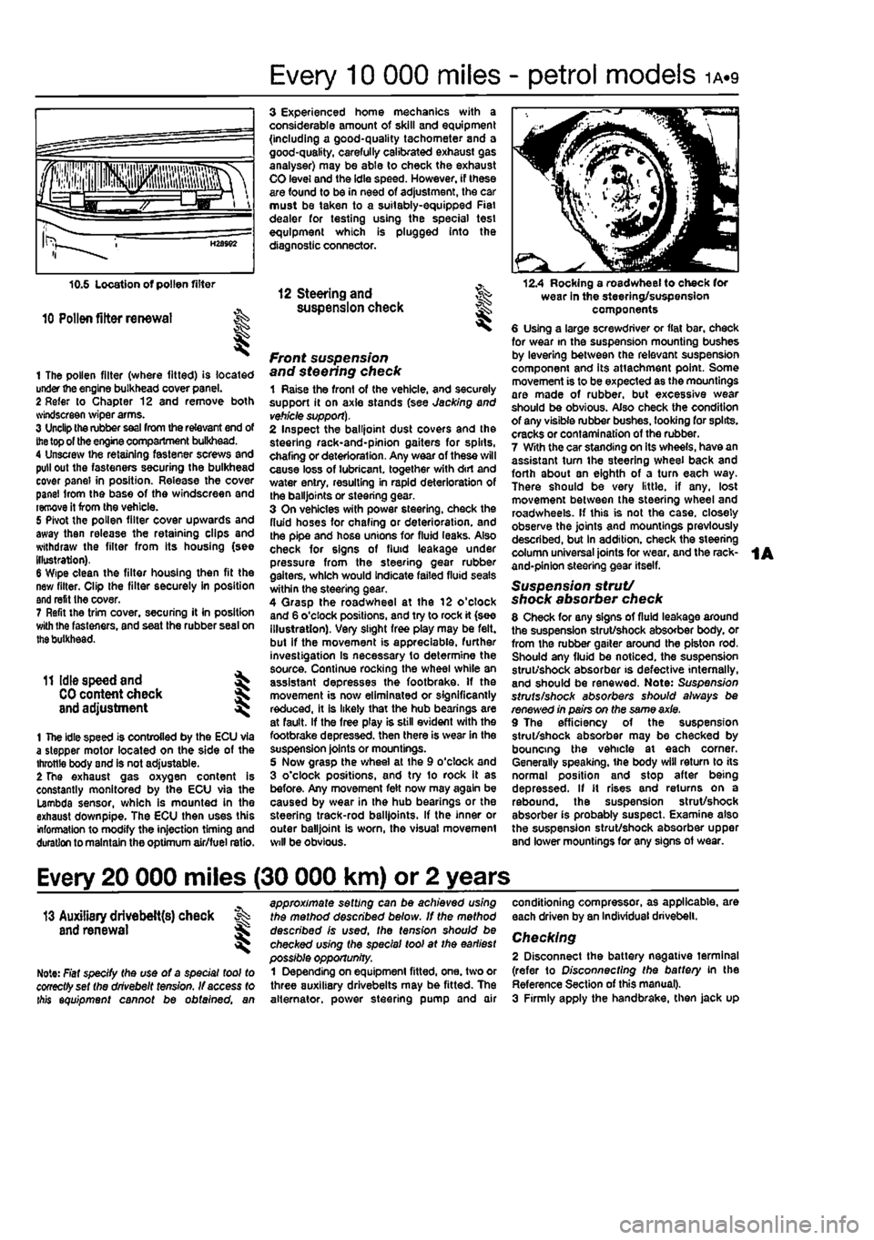
1 The pollen filter (where fitted) is located under the engine bulkhead cover panel. 2 Refer to Chapter 12 and remove both svindscreen wiper arms. 3 Unclip the rubber
seal
from the relevant end of
the
top of the engine compartment bulkhead. 4 Unscrew the retaining fastener screws and pull out the fasteners securing the bulkhead cover panel in position. Release the cover panel Irom the base of the windscreen and remove it from the vehicle. 5 Pivot the pollen filter cover upwards and away then release the retaining clips and withdraw the filter from its housing (see illustration). 6 Wipe clean the filter housing then fit the new filter. Clip the filter securely in position and refit the cover. 7 Refit the trim cover, securing it in position with Ihe fasteners, and seat the rubber seal on
the
bulkhead.
11 Idle speed and ^
CO
content check J and adjustment ^
1 The idle speed is controlled by the ECU via a stepper motor located on the side of the throttle body and is not adjustable. 2 The exhaust gas oxygen content is constantly monitored by the ECU via the Lambda sensor, which is mounted in the exhaust down pipe. The ECU then uses this information to modify the injection timing and duration to maintain the optimum air/fuel ratio.
3 Experienced home mechanics with a considerable amount of skill and equipment (including a good-quality tachometer and a good-quality, carefully calibrated exhaust gas analyser) may be able to check the exhaust CO level and the idle speed. However, if these are found to be in need of adjustment, the car must be taken to a suitably-equipped Fiat dealer for testing using the special test equipment which is plugged into the diagnostic connector.
12 Steering and ^ suspension check
front suspension and steering check 1 Raise the front of the vehicle, and securely support it on axle stands (see Jacking and
vehicle support).
2 Inspect the balljoint dust covers and the steehng rack-and-pinion gaiters for spirts, chafing or deterioration. Any wear of these will cause loss of lubricant, together with dirt and water entry, resulting in rapid deterioration of the balljoints or steering gear. 3 On vehicles with power steering, check the fluid hoses for chafing or deterioration, and the pipe and hose unions for fluid leaks. Also check for signs of fluid leakage under pressure from the steering gear rubber gaiters, which would indicate failed fluid seals within the steering gear. 4 Qrasp the roadwheel at the 12 o'clock and 6 o'clock positions, and try to rock it (see illustration). Very slight free play may be felt, but if the movement is appreciable, further investigation Is necessary to determine the source. Continue rocking the wheel while an assistant depresses the footbrake. If the movement is now eliminated or significantly reduced, it is likely that the hub bearings are at fault. If the free play is still evident with the footbrake depressed, then there is wear in the suspension joints or mountings. 5 Now grasp the wheel at the 9 o'clock and 3 o'clock positions, and try to rock it as before. Any movement felt now may again be caused by wear in the hub bearings or the steering track-rod balljoints. If the inner or outer balljoint is worn, the visual movement will be obvious.
12.4 Rocking a roadwheel to check for wear in the steering/suspension components 6 Using a large screwdriver or flat bar, check for wear in the suspension mounting bushes by levering between the relevant suspension component and its attachment point. Some movement is to be expected as the mountings are made of rubber, but excessive wear should be obvious. Also check the condition of any visible rubber bushes, looking for splits, cracks or contamination of the rubber. 7 With the car standing on its wheels, have an assistant tum the steering wheel back and forth about sn eighth of a turn each way. There should be very little, if any. lost movement between the steering wheel and roadwheels. If this is not the case, closely observe the joints and mountings previously described, but in addition, check the steering column universal joints for wear, and the rack-and-pinion steering gear itself.
Suspension strut/ shock absorber check 8 Check for any signs of fluid leakage around the suspension strut/shock absorber body, or from the rubber gaiter around the piston rod. Should any fluid be noticed, the suspension strut/shock absorber is defective internally, and should be renewed. Note: Suspension struts/shock absorbers should always be renewed in pairs on the same axle. 9 The efficiency of the suspension strut/shock absorber may be checked by bouncing the vehicle at each corner. Generally speaking, ihe body will return to its normal position and stop after being depressed. If it rises and returns on a rebound, the suspension strut/shock absorber is probably suspect. Examine also the suspension strut/shock absorber upper and lower mountings for any signs of wear.
Every 20 000 miles (30 000 km) or 2 years
13 Auxiliary drivebelt{s) check % and renewal ^
Note: Fiat specify the use of a special tool to cooectfyset the drivebelt tension. If access to ibis equipment cannot be obtained, an
approximate setting can be achieved using the method described below. If the method described is used, the tension should be checked using the special tool at the earliest possible opportunity. 1 Depending on equipment fitted, one. two or three auxiliary drivebelts may be fitted. The alternator, power steering pump and air
conditioning compressor, as applicable, are each driven by an Individual drivebelt.
Checking 2 Disconnect the battery negative terminal (refer to Disconnecting the battery in the Reference Section of this manual). 3 Firmly apply the handbrake, then jack up
Page 31 of 225
1A.12
Every 20 000 miles - petrol models
18.7 Lift up the cover and remove the filter element (18-va!ve engines) 9 Fit a new air (liter element In position, ensuring that the edges are securely seated 10 Refit the air cloaner cover, engage the rear retainers and secure with the three bolts.
19 Spark plug renewal
1 The correct functioning of the spark plugs is vital for the correct running and efficiency of the engine. It is essential that the plugs fitted are appropnate for the engine (a suitable type is specified at the beginning of this Chapter. If this type is used and the engine Is In good condition, the spark plugs should not need attention between scheduled replacement intervals Spark plug cleaning Is rarely necessary, and should not be attempted
19.2a Disconnecting tho HT leads from Iho spark plugs on 8-valve engines ...
19.4 Removing the spark plugs
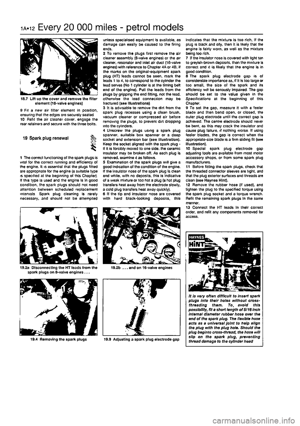
unless specialised equipment Is available, as damage can easily be caused to the firing ends. 2 To remove the plugs first remove the air cleaner assembly (8-vaive engines) or the a»r cleaner, resonator and inlet air duct (16-valve engines) with reference to Chapter 4A or 4B. if the marks on the original-equipment spark plug (HT) leads cannot be seen, mark the leads 1 to 4, to correspond to the cylinder the lead serves (No 1 cylinder is at the timing belt end of the engine). Pull the leads from the plugs by gripping the end fitting, not the lead, otherwise the lead conneciion may be Iractured (see illustrations) 3 It is advisable to remove the dirt from the spark plug recesses using a clean brush, vacuum cleaner or compressed air before removing the plugs, to prevent dirt dropping into the cylinders. 4 Unscrew the plugs using a spark plug spanner, suitable box spanner or a deep socket and extension bar (see illustration). Keep the socket aligned with the spark plug • If it is forcibly moved to one side, the ceramic insulator may be broken off. As each plug is removed examine 4 as fallows. 5 Examination of the spark plugs will give a good Indication of the condition of the engine. If the Insulator nose of the spark plug Is clean and white, with no deposits, this is Indicative of a weak mixture or too hot a plug (a hot plug transfers heal away from the electrode slowly, a cold plug transfers heat away quickly). 6 If the tip and insulator nose are covered with hard black-looking deposits, this
19.2b ... and on 16-valve engines
19.9 Ad|ustlng a spark plug electrode gap
indicates that the mixture Is too rich. If the plug is black and oily, then It is likely that the engine is fairly worn, as well as the mixture being too rich. 7 If the Insulator nose is covered with light tan to greyish-brown deposits, then the mixture Is correct and it is likely that (he engine Is in good condition. 6 The spark plug electrode gap is of considerable importance as, if it Is too large or too small, the size of the spark and its efficiency will be seriously impaired. The gap should be set to the value given in the Specifications at the beginning of this Chapter. 9 To set the gap. measure it with a feeler blade and then bend open, or closed, the outer plug elect/ode until the correct gap l9 achieved. The centre electrode should never be bent, as this may crack the insulator and cause plug I allure, if nothing worse. If using feeler blades, the gap is correct when the appropriate-size blade is a firm sliding fit (see illustration). 10 Special spark plug electrode gap adjusting tools are available from most motor accessory shops, or from some spark plug manufacturers, 11 Before fitting the spark plugs, check that the threaded connector sleeves are tight, and that the plug exterior surfaces and threads are clean (see Haynes Hint). 12 Remove the rubber hose (If used), and tighten the plug to the specified torque using the spark plug socket and a torque wrench, Refit the remaining spark plugs In the same manner. 13 Connect the HT leads In their correct order, and refit any components removed for access.
It is very often difficult to insert spark plugs into their holes without cross-threading them. To, avoid this possibility, fit a short length of Si 16 Inch Internal diameter rubber hose over the end of the spark plug. The flexible hose acts as a universal Joint to help align the plug with the plug hole. Should the plug beginto cross-thread, the hose will slip on the spark plug, preventing thread damage to the cylinder head
Page 40 of 225
ib-4 Component location - diesel models
Underbonnet view - turbo diesel model
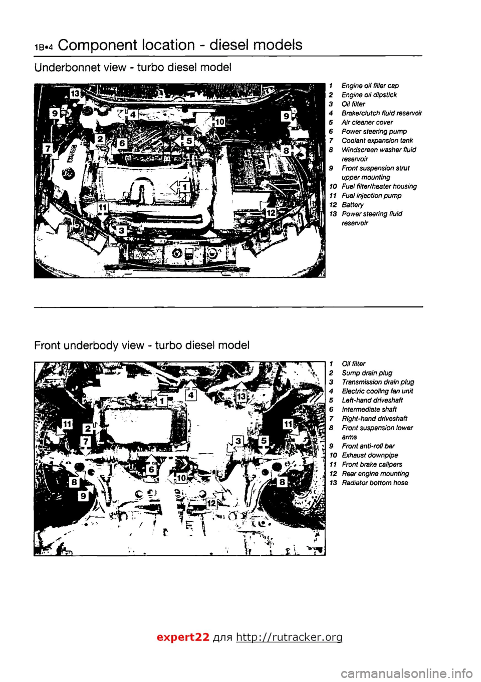
1 Engine oil filter
cap
2 Engine oil dipstick 3 Oil
tilter
4 Brake/clutch fluid
reservoir
5 Air cleaner
cover
6 Power steering pump 7 Coolant expansion
tank
8 Windscreen washer
fluid
reservoir 9 Front suspension strut upper mounting 10 Fuel filter/heater
housing
11
Fuel
injection pump 12 Battery 13 Power steering fluid reservoir
Front underbody view - turbo diesel model
1 Oil
fitter
2 Sump drain plug 3 Transmission drain plug 4 Electric cooling fan unit 5 Left-hand
driveshaft
6 Intermediate
shaft
7 Bight-hand
driveshaft
8 Front suspension lower arms 9 Front anti-roll
bar
10 Exhaust downpipe 11 Front brake calipers 12
Rear
engine mounting 13 Radiator bottom hose
expert22 fl/ia http://rutracker.org
Page 41 of 225
Component location - diesel models ib-s
Rear underbody view - turbo diesel model
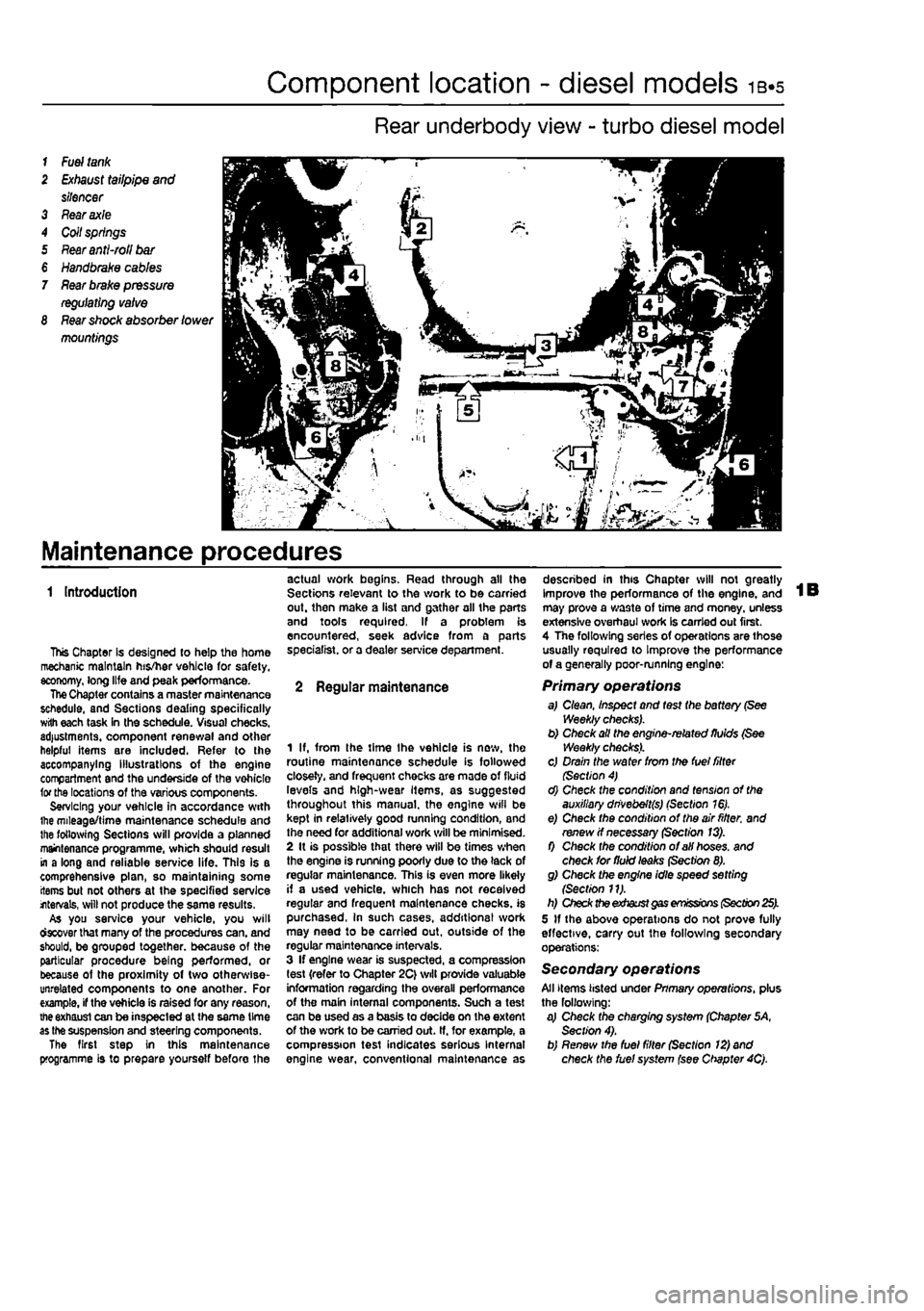
1
Fuel tank
2
Exhaust
tailpipe
and
silencer 3 Fear axle 4 Coil springs 5
Rear anti-roll bar
€
Handbrake cables
7
Rear brake pressure regulating valve
8
Rear shock
absorber
lower
mountings
Maintenance procedures
1 Introduction
This Chapter Is designed to help the home mechanic maintain his/her vehicle for safety, economy, long life and peak performance. The Chapter contains a master maintenance schedule, and Sections dealing specifically with each task in the schedule. Visual checks, adjustments, component renewal and other helpful items are included. Refer to the accompanying illustrations of the engine compartment and the underside of the vohicle for the locations of the various components. Servicing your vehicle in accordance with ihe mileage/time maintenance schedule and the following Sections will provide a planned maintenance programme, which should result in a long and reliable service life. This is a comprehensive plan, so maintaining some items but not others at the specified service internals, will not produce the same results. As you service your vehicle, you will ctecover that many of the procedures can. and should, be grouped together, because of the particular procedure being performed, or because of the proximity of two otherwise-unrelated components to one another. For example, if the vehicle is raised for any reason, the exhaust can be inspected at the same time as the suspension and steering components. The first step in this maintenance programme is to prepare yoursetf before the
actual work begins. Read through all the Sections relevant to the work to be carried out. then make a list and gather all the parts and tools required. If a problem is encountered, seek advice from a parts specialist, or a dealer service department.
2 Regular maintenance
1 If, from the time Ihe vehicle is new, the routine maintenance schedule is followed closely, and frequent checks are made of fluid levels and high-wear Items, as suggested throughout this manual, the engine wifl be kept in relatively good running condition, and the need for additional work will be minimised. 2 It is possible that there will be times when the engine is running poorly due to the lack of regular maintenance. This is even more likely if a used vehicle, which has not received regular and frequent maintenance checks, is purchased, in such cases, additions! work may need to be carried out, outside of the regular maintenance intervals. 3 If engine wear is suspected, a compression test {refer to Chapter 2C} will provide valuable information regarding the overall performance of the main internal components. Such a test can be used as a basis to decide on the extent of the work to be carried out. If, for example, a compression test indicates serious Internal engine wear, conventional maintenance as
described in this Chapter will not greatly improve the performance of the engine, and may prove a wa3te of time and money, unless extensive overhaul work Is carried out first. 4 The following series of operations are those usually required to Improve the performance of a generally poor-running engine:
Primary operations a,I Clean, Inspect and test the battery (See Weekly checks). b) Check all the engine-related fluids (See Weekly checks). c) Drain the water from the fuel filter (Section 4) d) Check the condition and tension of the auxiliary dnvebeft(s) (Section 16). e) Check the condition of the air fitter, and renew if necessary (Section 13). f) Check the condition of all hoses, and check for fluid leaks (Section 8). g) Check the engine idle speed setting {Section 11). h) Check the exhaust gas emissions (Section 25). 5 If the above operations do not prove fully effective, carry out the following secondary operations:
Secondary operations All items listed under Pnmary operations, plus the following: a) Check the charging system (Chapter 5A, Section 4). b) Renew the fuel filter (Section 12) and check the fuel system (see Chapter 4Q.
Page 45 of 225
Every 10 000 miles - diesel models ib«9
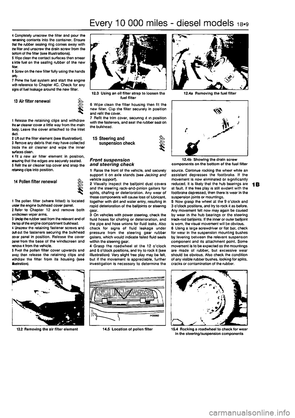
4 Completely unscrew the filter and pour the remaining contents into the container. Ensure (hat the rubber sealing ring comes away with
me
fitter and unscrew the drain screw from the
bottom
of tho filter (see illustrations). 5 Wipe clean the contact surfaces then smear
a
ittfe fuel on the sealing rubber of the new Nter. 6 Screw on the new filter fully using the hands orty. 7 Prime the fuel system and start the engine wth reference to Chapter 4C. Check for any signs of fuel leakage around the new filter.
13 Air fitter renewal
t Release the retaining clips and withdraw
Ihe
air cleaner cover a little way from the main body. Leave the cover attached to the inlet duct. 2 Lift out the filter element (see illustration). 3 Remove any debris that may have collected Inside the air cleaner and wipe the Inner surfaces clean. 4 Fit a new air filter element in position, ensuring that the edges are securely seated. 6 Refit the air cleaner top cover and snap the retaining clips into position.
14 Pollen filter renewal
t
1 The pollen filter (where fitted) Is located under the engine bulkhead cover pane). 2 Refer to Chapter 12 and remove both windscreen wiper arms. 3 Undp tho rubber seal from the relevant end of
the top
of the engine compartment bulkhead. 4 Unscrew the retaining fastener screws and Duiout the fasteners securing the bulkhead eovar panel in position. Release the cover panel from the base of the windscreen and remove it from the vehicle. 5 Pivot the pollen filter cover upwards and away then release the retaining clips and withdraw the filter from Its housing (see lustration).
12.3 Using an olt filter strap to loosen the fuel filter 6 Wipe clean the filter housing then fit the new filter, Clip the filter securely In position and refit the cover. 7 Refit the trim cover, secunng it >n position with the fasteners, and seat Ihe rubber seal on the bulkhead.
12.4a Removing the fuel filter
15 Steering and §S> suspension check ^
Front suspension and steering check 1 Raise the front of the vehicle, and securely support it on axle stands (see Jacking and vehicle support). 2 Visually Inspect the balljoint dust covers and the steering rack-and-pinion gaiters for splits, chafing or deterioration. Any wear of Ihese components will cause loss of lubricant, together with dirt and water entry, resulting in rapid deterioration of the balljoints or steering gear. 3 On vehicles with power steering, check the fluid hoses for chafing or deterioration, and the pipe and hose unions for fluid leaks. Also check for signs of fluid leakage under pressure from the steering gear rubber gaiters, which would indicate failed fluid seals within the steenng gear. 4 Grasp the roadwheel at the 12 o'clock and 6 o'clock positions, and try to rock it (see illustration). Very slight free play may be felt, but if the movement is appreciable, further investigation is necessary to determine the
fplllll iHpjiiisisps fa^aJw a LJgr >
H58B92
12.4b Showing the drain screw components on the bottom of the fuel filter source. Continue rocking the wheel while an assistant depresses the footbrake. If the movement Is now eliminated or significantly reduced, it is likely that the hub bearings are at fault. If the free ptay is still evident with the footbrake depressed, then there Is wear In the suspension joints or mountings. 5 Now grasp the wheel at the 9 o'clock and 3 o'clock positions, and try to rock it as before. Any movement felt now may again be caused by wear in the hub bearings or the steering track-rod balljoints. If the inner or outer balljoint Is worn, the visual movemont will be obvious. 6 Using a large screwdriver or flat bar. check for wear in the suspension mounting bushes by levering between the relevant suspension component and its attachment point. Some movement is to be expected as the mountings are made of rubber, but excessive wear should be obvious. Also check the condition of any visible rubber bushes, looking for splits, cracks or contamination of the rubber.
13.2 Removing the air filter element 14.5 Location of pollen filter 15.4 Rocking a roadwheel to check for wear in the steering/suspension components
Page 57 of 225
2A*10 SOHC (8-valve) petrol engine in-car repair procedures
Preparation for refitting 16 The mating faces of the cylinder head and cylinder block must be perfectly clean before
refitting
the head. Use a hard plastic or wooden scraper to remove all traces of gasket and carbon; also clean the piston crowns. Take padicular care when cleaning the piston crowns as the soft aluminium alloy is easily damaged. Make sure that the carbon is not afowed to enter the oil and water passages -Ihs is particularly important for the lubrication
system, as
carbon could block the oil supply to
Ihe
engine's components. Using adhesive tape
and
paper, seal the water, oil and bolt holes in tf« cylinder block. To prevent carbon entering twgap between the pistons and bores, smear
a
iittte grease in the gap. After cleaning each piston, use a small brush to remove all traces of grease and carbon from the gap, then wipe away the remainder with a clean rag. Clean all
ttie pistons
in the same way. 17 Check the mating surfaces of the cylinder block and the cylinder head for nicks, deep scratches and other damage. If slight, they may be removed carefully with a file, but if (xcassive, machining may be the only alternative to renewal. If warpage of the Cytodar head gasket surface is suspected, use a straight-edge to check it for distortion.
Refer
to Part 0 of this Chapter if necessary. 18 Check the condition of the cylinder head
MRS.
and particularly their threads, whenever
they are
removed. Wash the bolts In a suitable solvent, and wipe them dry. Check each bolt for any sign of visible wear or damage, renewing them if necessary.
Refitting 18 Before refitting Ihe assembled cylinder head, make sure that the head and block mating surfaces are perfectly clean, and that
the
bolt holes in the cylinder block have been
mopped
out to clear any oil. 20 Check that the camshaft and crankshaft sprocket timing marks are still aligned with tteir respective cylinder head and oil pump covtr marks as described in Section 2. 21 The new gasket should not be removed from its nylon cover until required for use. Fit
the
gasket dry, and make sure that the mating surfaces on the head and block are perfectly dean.
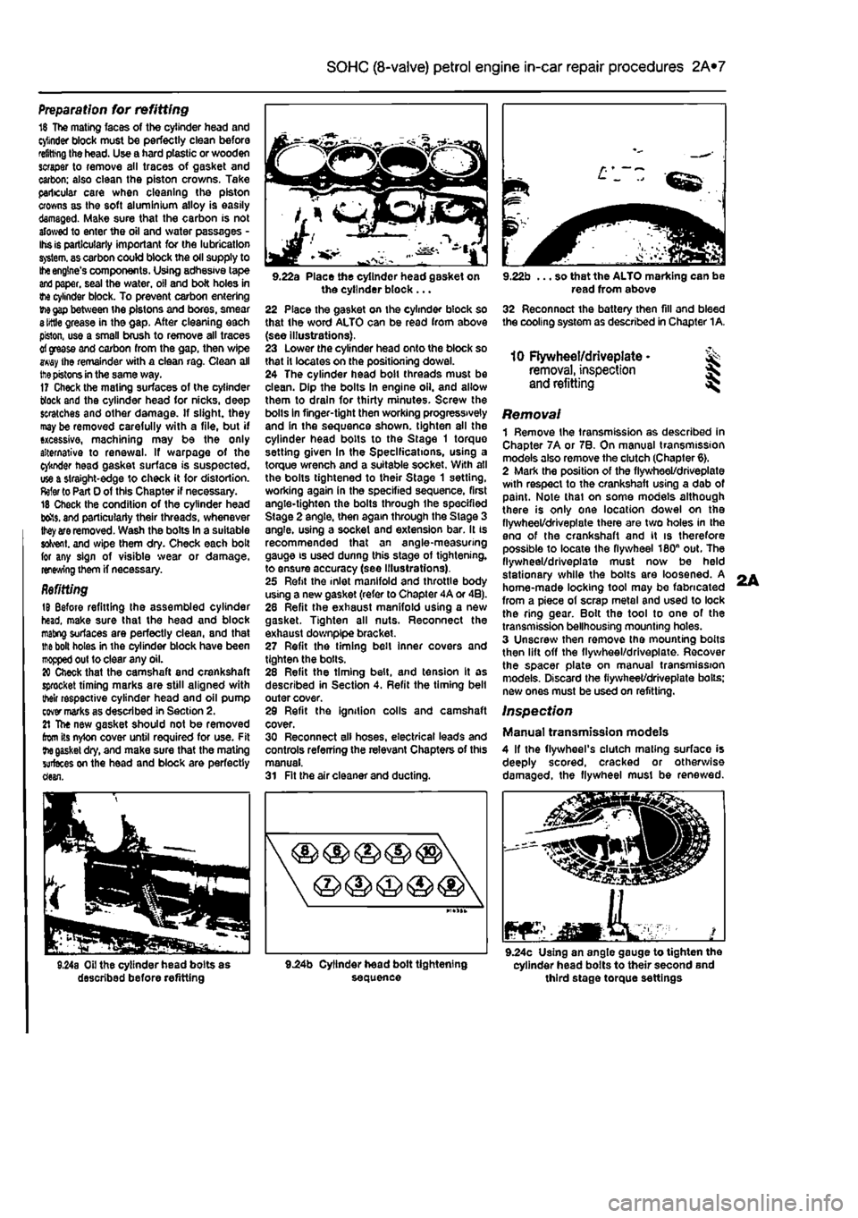
9.22a Place the cylinder head gasket on the cylinder block ... 22 Place the gasket on the cylinder block so that the word ALTO can be read from above (see illustrations). 23 Lower the cylinder head onto the block so that It locates on the positioning dowel. 24 The cylinder head bolt threads must be clean. Dip the bolts In engine oil. and allow them to drain for thirty minutes. Screw the bolls in finger-tight then working progressively and in the sequence shown, tighten all the cylinder head bolts to the Stage 1 torque setting given In the Specifications, using a torque wrench and a suitable socket. With all the bolts tightened to their Stage 1 setting, working again in the specified sequence, first angle-tighten the bolts through ihe specified Stage 2 angle, then again through the Stage 3 angle, using a socket and extension bar. It is recommended that an angle-measuring gauge is used dunng this stage of tightening, to ensure accuracy (see Illustrations). 25 Refit the inlet manifold and throttle body using a new gasket (refer to Chapter 4A or 4B). 28 Refit the exhaust manifold using a new gasket. Tighten all nuts. Reconnect the exhaust downplpe bracket. 27 Refit the timing belt inner covers and tighten the bolls. 28 Refit the timing belt, and tension It as described in Section 4. Refit the timing belt outer cover. 29 Refit the ignition colls and camshaft cover. 30 Reconnect all hoses, electrical leads and controls referring the relevant Chapters of this manual. 31 Fit the air cleaner and ducting.
9.22b ... so that the ALTO marking can be read from above 32 Reconnect the battery then fill and bleed the cooling system as described in Chapter 1A.
10 Flywheel/driveplate • ^ removal, inspection
and
refitting ^
Removal 1 Remove the transmission as described in Chapter 7A or 7B. On manual transmission models also remove the clutch (Chapter 6). 2 Mark the position of the flywheel/driveplate with respect to the crankshaft using a dab of paint. Note thai on some models although there is only one location dowel on the flywheel/driveplate there are two holes in the eno of the crankshaft and it is therefore possible to locate Ihe flywheel 180n out. The flywheel/driveplate must now be held stationary while the bolts are loosened. A home-made locking tool may be fabricated from a piece of scrap metal and used to lock the ring gear. Bolt the tool to one of the transmission bellhousing mounting holes. 3 Unscrew then remove the mounting bolts then lift off the flywheel/driveplate. Recover the spacer plate on manual transmission models. Discard the fiywheet/drivepiate boils; new ones must be used on refitting.
Inspection
Manual transmission models 4 If the flywheel's clutch mating surface is deeply scored, cracked or otherwise damaged, the flywheel must be renewed.
JEaMKA. mar 9.24c Using an angle gauge to tighten the cylinder head bolts to their second and third stage torque settings
L