fluids FIAT PUNTO 1994 176 / 1.G Workshop Manual
[x] Cancel search | Manufacturer: FIAT, Model Year: 1994, Model line: PUNTO, Model: FIAT PUNTO 1994 176 / 1.GPages: 225, PDF Size: 18.54 MB
Page 3 of 225
Contents
LIVING WITH YOUR FIAT PUNTO
Introduction to the Rat Punto Page 0-4 Safety lirstl Page 0*5
Roadside repairs If your car won't start Page 0*6 Jump starting Page 0*7 Wheel changing Page 0«8 Identifying teaks Page 0*9 Towing Page 0*9
Weekly checks Introduction Page 0*10 Underbonnet check points Page 0»10 Engine oil level Page 0*12 Coolant level Page 0*12 Brake fluid level Page 0*13 Power steering fluid level Page 0"13 Tyre condition and pressure Page 0*14 Automatic transmission fluid level Page 0«1S Screen washer fluid level Page 0«1S Wiper blades Page 0*15 Battery Page 0*16 Electrical systems Page 0-16
Lubricants and fluids Page 0*17
Tyre pressures Page 0*18
MAINTENANCE
Routine maintenance and servicing Rat Punto petrol models Page 1A«1 Servicing specifications Page 1A«2 Maintenance schedule Page 1A«3 Maintenance procedures Page 1A«6 Fiat Punto diesei models Page 1B-1 Servicing specifications Page 1B«2 Maintenance schedule Page 1B«3 Maintenance procedures Page 1B«5
expert22 fl/ia http://rutracker.org
Page 10 of 225
Roadside repairs 0.9
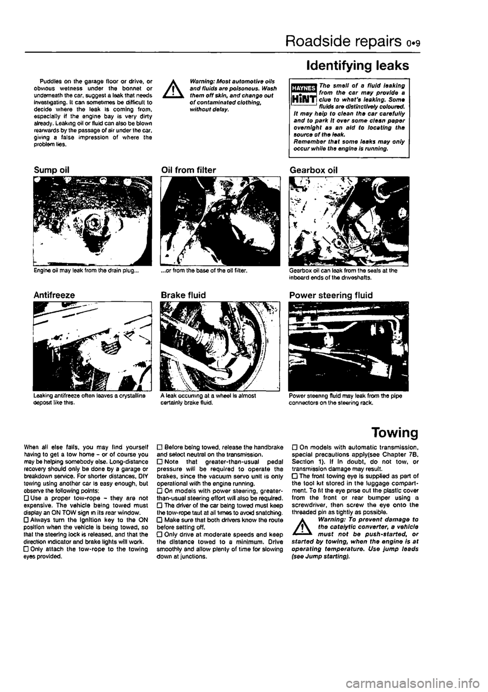
Puddles on the garage floor or drive, or obvious wetness under the bonnet or underneath the car, suggest a leak that needs Investigating. It can sometimes be difficult to decide where the leak is coming from, especially if the engine bay is very dirty already. Leaking oil or fluid can also be blown rearwards by the passage of air under the car, giving a false impression of where the problem lies.
A
Warning: Most automotive oils and fluids aro poisonous. Wash them off skin, and change out of contaminated clothing, without delay.
Identifying leaks
The smell of 0 fluid leaking from the car may provide a clue to what's leaking. Some fluids are distinctively coloured. It may help to clean the car carefully and to park It over some clean paper overnight as an aid to locating the source of the leak. Remember that some leaks may only occur while the engine is running.
Sump oil
Engine oil may leak from the drain plug...
Antifreeze
Leaking antifreeze often leaves a crystalline oeposit like this.
Oil from filter
A leak occurring at a wheel Is almost certainly brake fluid.
Gearbox oil
Gearbox oil can leak from the seals at the inboard ends of the drivoshafts.
Power steering fluid
Power steering fluid may leak from the pipe connectors on the steering rack.
When ail else falls, you may llnd yourself having to get a tow home - or of course you may be helping somebody else. Long-distance recovery should only be done by a garage or breakdown service. For shorter distances. OIY towing using another car is easy enough, but observe the following points: • Use a proper tow-rope - they are not expensive. The vehicle being towed must display an ON TOW sign in its rear window. • Always turn the Ignition key to the ON position when the vehicle is being towed, so that the steering lock is released, and that the direction indicator and brake lights will work. • Only attach the tow-rope to the towing eyes provided.
• Before being towed, release the handbrake and select neutral on the transmission. • Note that greater-then-usual pedal pressure will be required to operate the brakes, since the vacuum servo unit is only operational with the engine running. • On models with power steering, greater-than-usual steering effort will also be required. • The driver of the car being towed must keep the tow-rope taut at all times to avoid snatching. • Make sure that both drivers know the route before setting off. • Only dnve at moderate speeds and keep the distance towed to a minimum. Drive smoothly and allow plenty of time for slowing down at junctions.
Towing
• On models with automatic transmission, special precautions apply(see Chapter 7B. Section 1). If In doubt, do not tow, or transmission damage may result. • The front towing eye is supplied as part of the tool kit stored in the luggage compart-ment. To fit the eye pnse out the plastic cover from the front or rear bumper using a screwdriver, then screw the eye onto the threaded pin as tightly as possible.
A
Warning: To prevent damage to the catalytic converter, e vehicle must not be push'started, or started by towing, when the engine is at operating temperature. Use jump leads (see Jump starting).
Page 13 of 225
o*i2 Weekly checks
Engine oil level
Before you start • Make euro that your cor is on level ground. • Check ihe oil level oefore ihe cor is driven, or at least 5 minutes alter the engine has been switched off.
HHifffl If tho oil Is checked rTf"™^ Immediately after driving the IHlAIT vehicle,
some
of the oil will " remain In the upper engine components, resulting in on inaccurate reading on the dipstick!
The correct oil Modern engines place great demands on their oil. It Is very important that the correct oil for your car is used
Car Care • If you have to add oil frequently, you should check whother you have any oil leaks. Place some clean paper under the car overnight, and check for stains In the morning. If there are no leaks, the engine may be burning oil.
• Always maintain the level between the upper and lower dipstick marks (see pholo 2). If Ihe level Is too low
sqvoio
engine damage may oecur. Oil seal failure may result if tho engine is overfilled by adding too much oil.
I
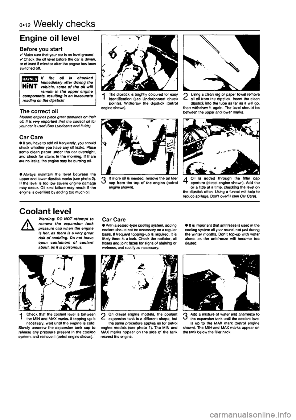
Tho dipstick is brightly coloured for easy identification (seo Under bonnet check points). Withdraw the dipstick (petrol engine shown).
3
If more oil is needed, remove the oil filler cap Irom the top of the ongine (petrol engine shown).
SI i J
2
Using a clean rag or paper towel remove all oil from the dipstick. Insert the clean dipstick into the tube as far as it will go, then withdraw it again. The level should be between the upper and lower marks.
4
Oil Is added through the filler cap aperture (diesel engine shown). Add the oil a little at a time, checking the level on the dipstick often. Using a funnel will help to reduce spillage. Don't overfill (see Car Care).
Coolant level
A
Warning: DO NOT attempt to remove the expansion tank pressure cap when the engine is hot, as there is a very great risk of scalding. Do not leave open containers of coo/ant about, as It is poisonous.
Car Care • With a sealed-type cooling system, adding coolant should not be necessary on a regular basis. If frequent topping-up is required, it is likely there Is a leak. Check the radiator, all hoses and Joint faces for signs of staining or wetness, and roctify as necessary.
• It is important that antifreeze is used in the cooling system all year round, not just during the winter months. Don't top-up with water alone, as the antifreeze will become too diluted.
H Check that the coolant level is between I the MIN and MAX marks, il topping up is necessary, wait until tho engine is cold. Slowly unscrew the expansion tank cap to release any pressure present in the cooling system, and remove it (petrol engine shown).
2
On diesel engine models, Ihe ooolant expansion tank is a different shape, but Ihe same procedure applies as for petrol engine models (see photo 1). Tho MlN and MAX marks appear on the side of tlie tank neorosl the engine.
3
Add a mixture of water and antifreeze to the expansion tank until the coolant level is up to the MAX mark (petrol engine shown), The MIN and MAX marks appear on the tank below the filler neck.
Page 18 of 225
Lubricants and fluids 0.17
Lubricants and fluids
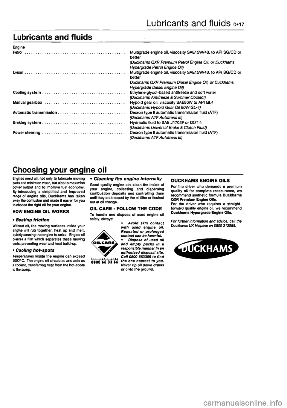
Engine Petrol Multigrade engine oil, viscosity SAE15W/40, to API SG/CD or better (Duckhams QXR Premium Petrol Engine Oil, or Duckhams Hypergrade Petrol Engine Oil) Diesel Multigrade engine oil, viscosity SAE15W/40, to API SG/CD or better Duckhams QXR Premium Diesel Engine Oil, or Duckhams Hypergrade Diesel Engine Oil) Cooling system Ethylene glycol-based antifreeze and soft water (Duckhams Antifreeze & Summer Coolant) Manual gearbox Hypoid gear oil, viscosity SAE80W to API GL4 (Duckhams Hypoid Gear Oil SOW GL-4) Automatic transmission Dexron type II automatic transmission fluid (ATF) (Duckhams ATF Autotrans III) Braking system Hydraulic fluid to SAE J1703F or DOT 4 (Duckhams Universal Brake & Clutch Fluid) Power steering Dexron type II automatic transmission fluid (ATF) (Duckhams ATF Autotrans Hi)
Choosing your engine oil
Engines need oil. not only to lubricate moving parts and minimise wear, but also to maximise power output and to Improve fuel economy. By introducing a simplified and improved range of engine oils. Duckhams has taken away the confusion and made it easier for you lo choose the right oil for your engine.
HOW ENGINE OIL WORKS
• Beating friction Without oil. the moving surfaces inside your engine will rub together, heat up and melt, quickly causing the engine to seize. Engine oil creates a film which separates these moving parts, preventing wear and heat build-up.
• Cooling hot-spots Temperatures Inside the engine can exceed 1000°
C.
The engine oil circulates and acts as a coolant, transferring heat from the hot-spots to the sump.
• Cleaning the engine internally Good quality engine oils clean the Inside of your engine, collecting and dispersing combustion deposits and controlling them until they are trapped by the oil niter or flushed out at oil change.
OIL CARE - FOLLOW THE CODE To handle and dispose of used engine oil safety, always: • Avoid skin contact with used engine oil. Repeated or prolonged contact can be harmful. • Dispose of used oil and empty packs In a responsible manner In an authorised disposal site. tti Call 0800 663366 to find qIqq f £ the one nearest to you. Never tip oil down drains or onto the ground.
DUCKHAMS ENGINE OILS For the driver who demands a premium quality oil for complete reassurance, we recommend synthetic formula Duckhama QXR Premium Engine Oils. For the driver who requires a straight-forward quality engine oil, we recommend Duckhams Hypergrade Engine Ote.
For further information and advice, call the Duckhams UK Helpline on 0800 212988.
^SGCKHAMS
Page 21 of 225
ia.2 Servicing specifications - petrol models
Lubricants and fluids Refer to end ot Weekly checks on page 0*17
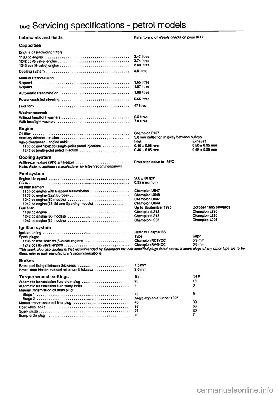
Capacities Engine oil (including filter) 1108 cc engine 3.47 litres 1242 cc (8-valvB) engine 3.74 litres 1242 cc (16-valve) engine 2.80 litres Cooling system 4,6 litres
Manual transmission 5-spee d 1.65 litres 6-spee d 1.87 litres Automatic transmission 1.98 litres Power-assisted steering 0.65 Irtres Fuel tank 47 litres Washer reservoir Wllhouthesdllghl washers 2.5 litres With headlight washers 7.0 litres
Engine Olf niter - Champion F107 Auxiliary drivebelt tension 5.0 mm deflection midway between pulleys Valve clearances - engine cold: Inlet Exhaust 1108 cc and 1242 cc (single-point petrol injection) 0.40±0.05mm 0.50±0.05mm 1242 cc (multi-point petrol Injection 0.40 1 0.05 mm 0.45 1 0.05 mm
Cooling system Antifreeze mixture (50% antifreeze) Protection down to -35"C Note: Refer to antifreeze manufacturer for latest recommendations.
Fuel system Engine idle speed . 900 * 50 rpm CO 0.35 maximum Air filter element: 1108 cc engine with 6-speed transmission -... Champion U647 1108 cc engine (Easl Europe) Champion U648 1242 cc engine (60 models) Champion U647 1242
CO
engine (75.85 and Sporting models) Champion U649 Fuel filler: Up to September 1995 October 1995 onwards 1108 cc engine Champion L213 Champion L225 1242 cc engine (60 models) Champion L213 Champion 1225 1242 cc engine {75 models) Champion L203 Champion L225
Ignition system Ignition liming Refer to Chapter 58 Spark plugs: Type Gap* 1108 cc and 1242 cc (6-valve) engines Champion RC9YCC 0.9 mm 1242 cc (16-valve) engine ,... Champion RA4HCC 0.8 mm The spark plug gap quoted Is Diet recommenced by Champion for their specined plugs listed above. If spar* plugs of any other type ere to be fitted, refer to their manufacturer's recommendations. Brakes Brake pad lining minimum thickness 15 mm Brake shoe friction material minimum thickness 2.0 mm
Torque wrench settings Nm itrfft Automatic transmission lluld drain plug 25 10 Automatic transmission fluid sump bolts 4 3 Manual transmission oil drain plug: Stage 1 12 9 Stage 2 Angle-lighten a further 180" Manual transmission oil filler plug 40 30 Roadwheel bolts 86 83 Spark plugs 27 20 Sump drain plug 10 7
Page 25 of 225
ia«6 Component location - petrol models
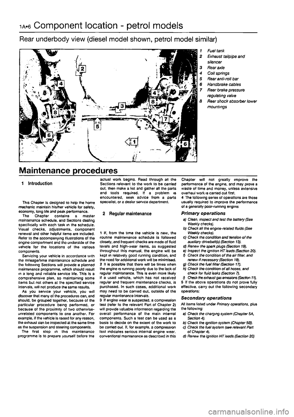
Rear underbody view (diesel model shown, petrol model similar)
1 Fuel
tank
2
Exhaust
tailpipe
and
silencer 3
Rear axle
4 Coll
springs
5
Rear
anti-mil
bar
6
Handbrake cables
T
Rear brake pressure
regulating
valve
S
Rear
shock absorber lower mountings
Maintenance procedures
1 Introduction
This Chapter is designed to help the home mechanic maintain his/her vehicle (or safety, eoonomy, long life and peak performance. The Chapter contains a master maintenance schedule, and Sections dealing specifically with each task in the schedule. Visual checks. ad}ustments, component renewal and other helpful Items are included. Refer to the accompanying Illustrations of the engine compartment and tho underside of the vehicle for the locations of the various components. Servicing your vehicle in accordance with ihe mlleaget/time maintenance schedule and the following Sections will provide a planned maintenance programme, which should result m a long and reliable service life. This Is a comprehensive plan, so maintaining some Items but not others at the specified service Intervals, will not produce the same results. As you service your vehicle, you will discover that many of the procedures can, and should, be grouped together, because of the particular procedure being performed, or because of the proximity of two otherwise-unrelated components to one another. For example, if the vehicle Is raised for any reason, the exhaust can be inspected at the same time as the suspension and steering components. The first step in this maintenance programme is to prepare yoursell before tne
actual work begins. Read through all the Sections relevant to the work to be carried out, then make a list and gather all the parts and tools required. If a problem is encountered, seek advice from a parts specialist, or a dealer service department.
2 Regular maintenance
1 If. from the time the vehicle is new, the routine maintenance schedule is followed closely, and frequent checks are made of fluid levels and high-wear items, as suggested throughout this manual, the engine will be kept in relatively good running condition, and the need for additional work will be minimised. 2 II is possible that there will be times when the engine rs running poorly due to the lack of regular maintenance. This is even more likely If a used vehicle, which has not received regular and frequent maintenance checks, is purchased. In such cases, additional work may need to be carried out. outside of the regular maintenance intervals. 3 If engine wear is suspected, a compression test (refer to the relevant Part of Chapter 2) will provide valuable information regarding the overall performance of the main internal components. Such a test can be used as a basis to decide on the extent of the work to bo carried out. II, for example, a compression test indicates serious internal engine wear, conventional maintenance as described in this
Chapter will not greatly improve the performance of the engine, and may prove a waste of time and money, unless extensive overhaul work is carried out first. 4 The following series of operations are those usually required to improve the performance of a generally poor-running engine:
Primary operations a) Cloan, inspect and test the battery
(See
Weekly checks), b) Check alt the engine-related fluids (See Weekly checks). c) Check the condition and tension of the auxiliary drivebeft($) (Section 13). d) Renew the spark plugs (Section 19). e) Inspect the ignition HT leads (Section 20). 0 Check the condition of the air filter, and renew if necessary (Section 18). g) Check the fuel filter (Section 17). h) Check tho condition of ell hoses, and check for fluid leaks (Sect/on 7). i) Check theexhaust
gas emissions (Section 11).
5 If the above operations do not prove fully effective, carry out the following secondary operations;
Secondary operations All items listed under Primary operations, plus the following; e) Check the charging system (Chapter 5K Section 4). b) Check the ignition system (Chapter 58). c) Check tho fuel system (see relevant Part of Chapter
4).
d) Renew the ignition HT leads (Section 20)
Page 38 of 225
1B.2
Servicing specifications - diesel models
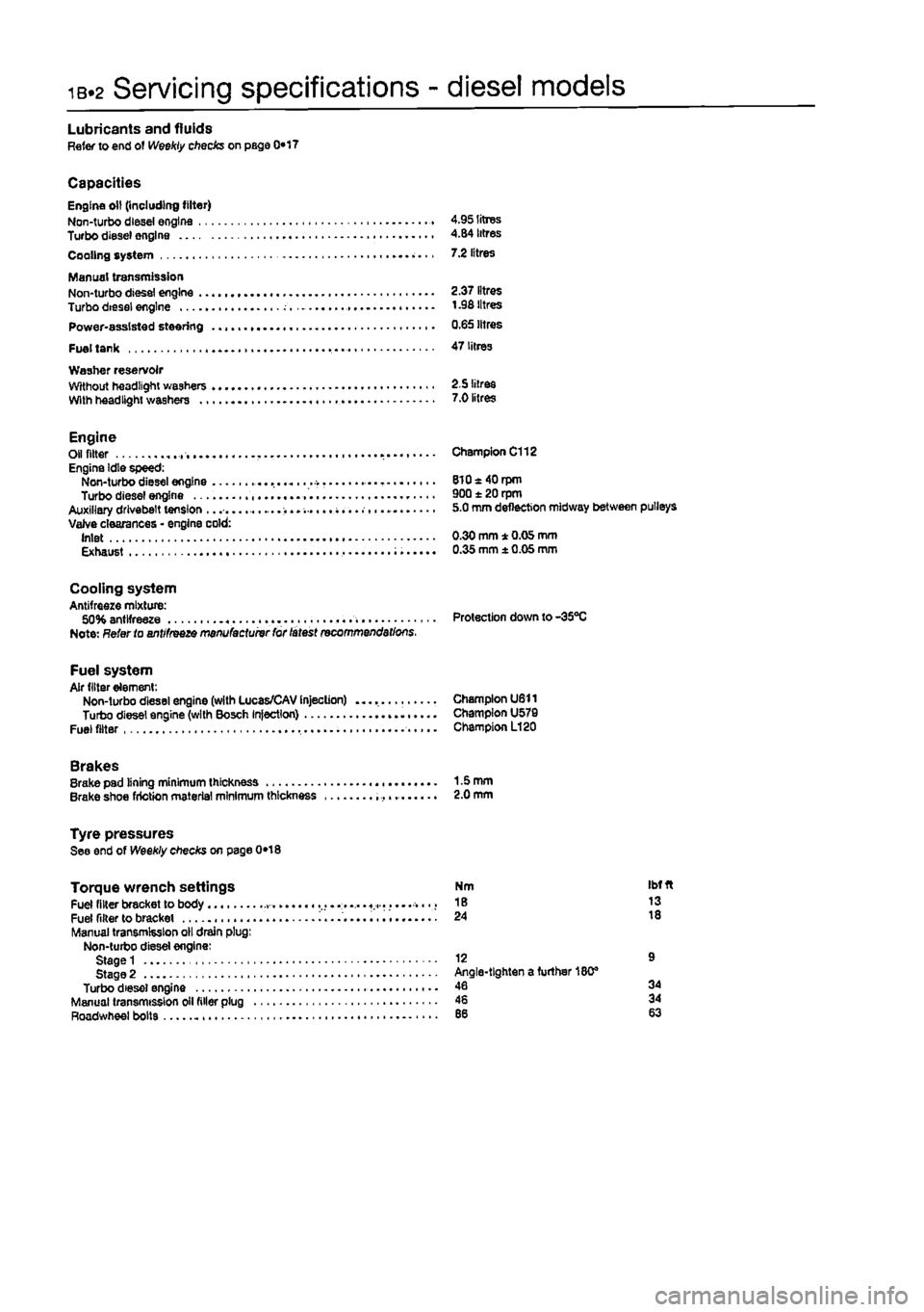
Lubricants and fluids Refer to end of Weekly checks on page 0*17
Capacities Engine oil (including filter) Non-turbo diesei engine 4.95 litres Turbo diesel engine 4.84 litres Cooling system 7.2 litres
Manual transmission Non-turbo diesel engine 2.37 litres Turbo diesei engine t .98 litres Power-assisted steering 0.65 litres
Fuel tank 47 litres Washer reservoir Without headlight washers 2.5 litres With headlight washers 7.0 litres
Engine Oil fitter Engine Idle speed: Non-turbo diesel engine Turbo diesel engine Auxiliary drivebelt tension ...... Valve clearances • engine cold: Inlet Exhaust
Champion C112
8l0«40rpm 900 ± 20 rpm 5.0 mm deflection midway between pulleys
0.30 mm * 0.05 mm 0.35 mm ± 0.05 mm
Cooling system Antifreeze mixture: 50% antifreeze Protection down to-35°C Note: Refer to antifreeze manufactuivr for latest recommendations.
Fuel system Air filter element: Non-turbo diesel engine (with Lucas/CAV Injection) Champion U611 Turbo diesel engine (with Bosch Injection) Champion U579 Fuel filter Champion L120
Brakes Brake pad lining minimum thickness 1-5 mm Brake shoe friction material minimum thickness 2.0 mm
Tyre pressures See end of Weekly checks on page 0*18
Torque wrench settings Fuel filter bracket to body ..... « Fuel filter to bracket i........ Manual transmission oil drain plug: Non-turbo diesel engine: Stage 1 Stage 2 Turbo diesel engine Manual transmission oil filler plug Roadwheel bolts
Nm Ibfft 18 13 24 18
12 9 Angle-tighten a further 180® 46 34 46 34
Page 41 of 225
Component location - diesel models ib-s
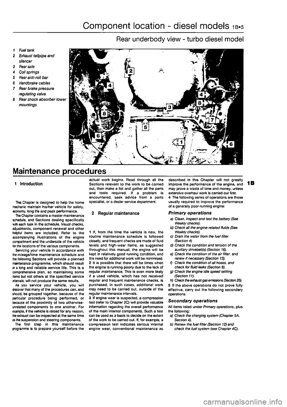
Rear underbody view - turbo diesel model
1
Fuel tank
2
Exhaust
tailpipe
and
silencer 3 Fear axle 4 Coil springs 5
Rear anti-roll bar
€
Handbrake cables
7
Rear brake pressure regulating valve
8
Rear shock
absorber
lower
mountings
Maintenance procedures
1 Introduction
This Chapter Is designed to help the home mechanic maintain his/her vehicle for safety, economy, long life and peak performance. The Chapter contains a master maintenance schedule, and Sections dealing specifically with each task in the schedule. Visual checks, adjustments, component renewal and other helpful items are included. Refer to the accompanying illustrations of the engine compartment and the underside of the vohicle for the locations of the various components. Servicing your vehicle in accordance with ihe mileage/time maintenance schedule and the following Sections will provide a planned maintenance programme, which should result in a long and reliable service life. This is a comprehensive plan, so maintaining some items but not others at the specified service internals, will not produce the same results. As you service your vehicle, you will ctecover that many of the procedures can. and should, be grouped together, because of the particular procedure being performed, or because of the proximity of two otherwise-unrelated components to one another. For example, if the vehicle is raised for any reason, the exhaust can be inspected at the same time as the suspension and steering components. The first step in this maintenance programme is to prepare yoursetf before the
actual work begins. Read through all the Sections relevant to the work to be carried out. then make a list and gather all the parts and tools required. If a problem is encountered, seek advice from a parts specialist, or a dealer service department.
2 Regular maintenance
1 If, from the time Ihe vehicle is new, the routine maintenance schedule is followed closely, and frequent checks are made of fluid levels and high-wear Items, as suggested throughout this manual, the engine wifl be kept in relatively good running condition, and the need for additional work will be minimised. 2 It is possible that there will be times when the engine is running poorly due to the lack of regular maintenance. This is even more likely if a used vehicle, which has not received regular and frequent maintenance checks, is purchased, in such cases, additions! work may need to be carried out, outside of the regular maintenance intervals. 3 If engine wear is suspected, a compression test {refer to Chapter 2C} will provide valuable information regarding the overall performance of the main internal components. Such a test can be used as a basis to decide on the extent of the work to be carried out. If, for example, a compression test indicates serious Internal engine wear, conventional maintenance as
described in this Chapter will not greatly improve the performance of the engine, and may prove a wa3te of time and money, unless extensive overhaul work Is carried out first. 4 The following series of operations are those usually required to Improve the performance of a generally poor-running engine:
Primary operations a,I Clean, Inspect and test the battery (See Weekly checks). b) Check all the engine-related fluids (See Weekly checks). c) Drain the water from the fuel filter (Section 4) d) Check the condition and tension of the auxiliary dnvebeft(s) (Section 16). e) Check the condition of the air fitter, and renew if necessary (Section 13). f) Check the condition of all hoses, and check for fluid leaks (Section 8). g) Check the engine idle speed setting {Section 11). h) Check the exhaust gas emissions (Section 25). 5 If the above operations do not prove fully effective, carry out the following secondary operations:
Secondary operations All items listed under Pnmary operations, plus the following: a) Check the charging system (Chapter 5A, Section 4). b) Renew the fuel filter (Section 12) and check the fuel system (see Chapter 4Q.
Page 199 of 225
Suspension and steering 10*11
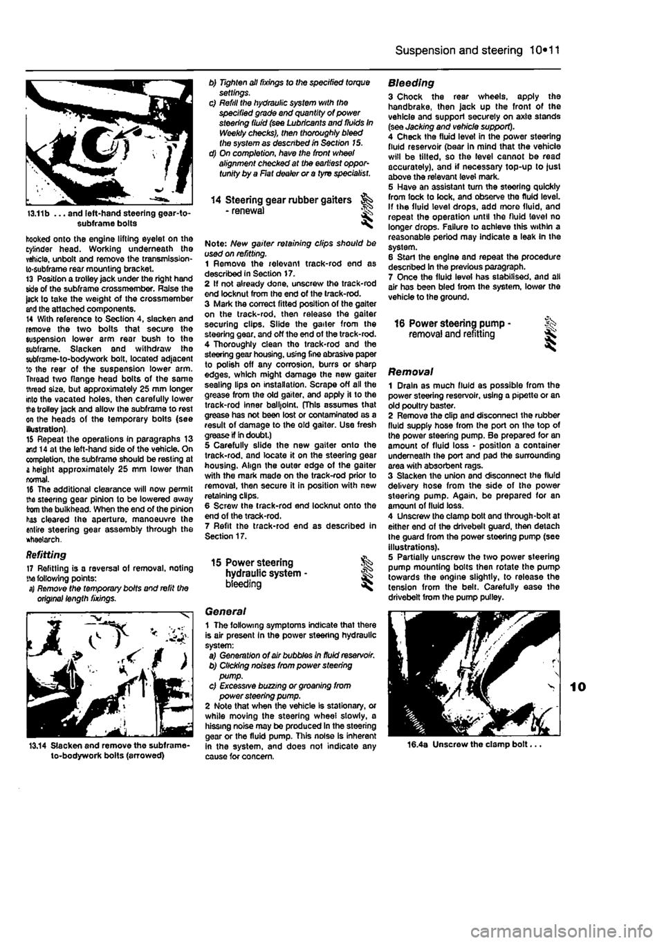
13.11b ... and left-hand steering gear-to-subframe bolts
hooked onto the engine lifting eyelet on the cylinder head. Working underneath the vehicle, unbolt and remove the transmission-lo-subframe rear mounting bracket. 13 Position a trolley jack under the right hand skle of the subframe crossmember. Raise the jack to take the weight of the crossmember
and
the attached components. 14 With reference to Section 4, slacken and remove the two bolts that secure the suspension lower arm rear bush to the subframe. Slacken and withdraw the subframe-to-bodywork bolt, located adjacent to the rear of the suspension lower arm. Throad two flange head bolts of the same thread size, but approximately 25 mm longer into the vacated holes, then carefully lower
the
trolley jack and allow ihe subframe to rest on the heads of the temporary bolts (see (lustration), 15 Repeat the operations in paragraphs 13 end 14 at the left-hand side of the vehicle. On completion, the subframe should be resting at
&
height approximately 25 mm lower than normal. 16 The additional clearance will now permit the steering gear pinion to be lowered away from the bulkhead. When the end of the pinion has cleared Ihe aperture, manoeuvre the entire steering gear assembly through the *tiae?arch.
Refitting 17 Refitting is a reversal of removal, noting
the
following points: s) Remote the temporary bolts and refit the original length fixings.
13.14 Slacken and remove the subframe-to-bodywork bolts (arrowed)
b) Tighten all fixings to the specified torque settings. c) Refill the hydraulic system with the specified grade and quantity of power steering fluid (see Lubricants and fluids In Weekly checks), then thoroughly bleed the system as described in Section 15. d) On completion, have the front wheel alignment checked at the earliest oppor-tunity by a Flat dealer or a tyre specialist.
14 Steering gear rubber gaiters - renewal <
Note: New gaiter retaining clips should be used on refitting. 1 Remove the relevant track-rod end as described in Section 17. 2 If not already done, unscresv the track-rod end locknut from Ihe end of the track-rod. 3 Mark the correct fitted position of the gaiter on the track-rod, then release the gaiter securing clips. Slide the gailer from the steering gear, and off the end of the track-rod. 4 Thoroughly clean tho track-rod and the steering gear housing, usrng fine abrasive paper to polish off any corrosion, burrs or sharp edges, which might damage the new gaiter sealing lips on installation. Scrape off all the grease from the old gaiter, and apply it to the track-rod inner balljoint. (This assumes that grease has not been lost or contaminated as a result of damage to the old gaiter. Use fresh crease if In doubt.) 5 Carefully slide the new gaiter onto the track-rod. and locate it on the steering gear housing. Align the outer edge of the gaiter with the mark made on the track-rod prior to removal, then secure it in position with new retaining clips. 6 Screw the track-rod end locknut onto the end of the track-rod. 7 Refit the track-rod end as described in Section 17.
15 Power steering hydraulic system • bleeding ^
General 1 The following symptoms indicate that there is air present In the power steering hydraulic system: a) Generation of air bubbles in fluid reservoir. b) Clicking noises from power steering pump. c) Excessive buzzing or groaning from power steering pump. 2 Note that when the vehicle Is stationary, or while moving the steering wheel slowly, a hissing noise may be produced In the steering gear or the fluid pump. This noise is inherent in the system, and does not indicate any cause for concern.
Bleeding 3 Chock the rear wheels, apply the handbrake, then jack up the front of the vehicle and support securely on axle stands (see Jacking and vehicle support). 4 Check the fluid level in the power steering fluid reservoir (bear in mind that the vehicle will be tilted, so the level cannot be read accurately), and if necessary top-up to just above the relevant level mark. 5 Have an assistant tum the steering quickly from lock to lock, and observe tho fluid level, if the fluid level drops, add more fluid, and repeat the operation until the fluid level no longer drops. Failure to achieve this within a reasonable period may indicate a leak in the system. 6 Stan the engine and repeat the procedure described In the previous paragraph. 7 Once the fluid level has stabilised, and all air has been bled from the system, lower the vehicle to the ground.
16 Power steering pump - Sk removal and refitting ^
Removal 1 Drain as much fluid as possible from the power steering reservoir, using a pipette or an old poultry baster. 2 Remove the clip and disconnect the rubber fluid supply hose from the port on the top of the power steering pump. Be prepared for an amount of fluid loss • position a container underneath the port and pad the surrounding area with absorbent rags. 3 Slacken the union and disconnect the fluid delivery hose from the side of the power steering pump. Again, be prepared for an amount of fluid loss. 4 Unscrew tho clamp bolt and through-bolt at either end of the drivebelt guard, then detach Ihe guard from the power steering pump (see illustrations). 5 Partially unscresv the two power steering pump mounting bolts then rotate the pump towards the engine slightly, to release the tension from the belt. Carefully ease the drivebelt from the pump pulley.
16.4a Unscrew the clamp bolt...
Page 200 of 225
10*12 Suspension and steering
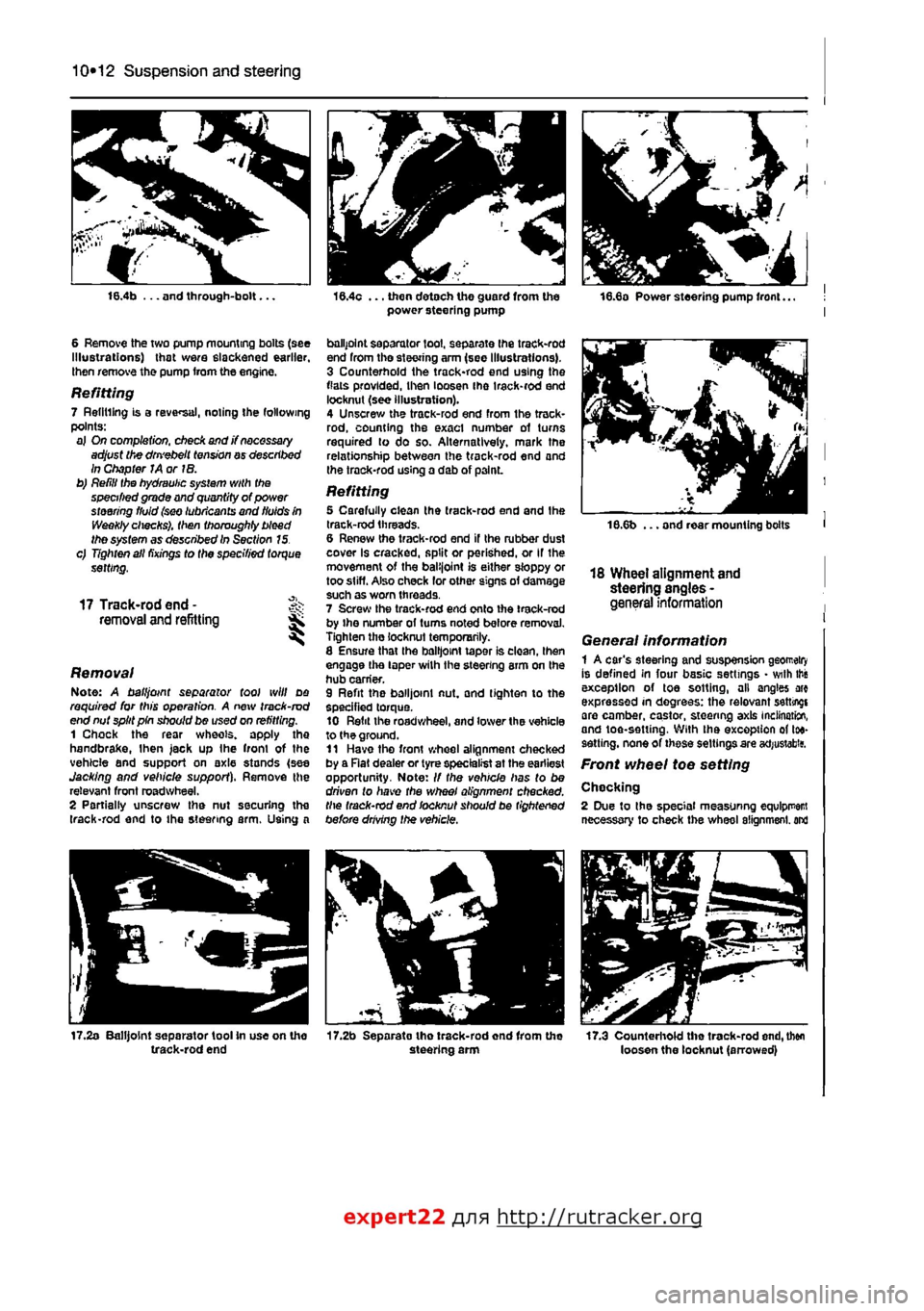
16.4b ... and through-bolt...
6 Remove the two pump mounting bolts (see Illustrations) that were slackened earlier, then remove the pump from the engine.
Refitting 7 Refilling is a reversal, noting the following points: a) On completion, check and j? necessary adjust the dm'ebelt tension ay described In Chapter JA or IB. b) Refill the hydraulic system with the specified grade and quantity of power steering fluid (sw lubricants and fluids in Weekly checks), then thoroughly bleed the system as described In Section 15. c) Tighten all fixings to the specified torque setting,
17 Track-rod end -removal and refitting ^ S
Removal Note: A ball joint separator tool will do required for this operation. A new track-rod end nut split pin should be used on refitting. 1 Chock the rear wheels, apply the handbrake,
I
hen jack up Ihe front of the vehicle and support on axle stands (see Jacking and vehicle support). Remove the relevant front roadwheel. 2 Partially unscrew the nut securing the (rack-rod end to the steering arm. Using a
17.2a Balljoint separator tool In use on the track-rod end
16.4c ... then detach the guard from the power steering pump
ballpoint separator tool, separate Ihe track-rod end from tho steering arm (see Illustrations). 3 Counterhold the track-rod end using the flats provided, then loosen ihe irack-rod end locknut (see illustration). 4 Unscrew the track-rod end from the track-rod, counting the exact number of turns required to do so. Alternatively, mark the relationship between the track-rod end and the trock-rod using a dab of p3lnL
Refitting 5 Carefully clean the track-rod end and the track-rod threads. 6 Renew the track-rod end if the rubber dust cover Is cracked, split or perished, or If the movement of the balijoint is either sloppy or too stiff. Also check lor other signs of damage such as worn threads. 7 Screw the track-rod end onto ihe track-rod by ihe number ol turns noted before removal. Tighten the locknut temporarily. 8 Ensure that Ihe balljoint taper is clean, then engage the taper wilh the steering arm on the hub carrier. 9 Refit the balljoint nut, and tighten to the specified torque. 10 Refit the roadwheel, and lower the vehicle to the ground. 11 Have tho front wheel alignment checked by a Rat dealer or tyre specialist at the earliest opportunity. Note: // the vehicle has to be driven to have the wheel alignment checked, the track-rod end locknut should be tightened before drMng the vehicle.
17.2b Separato tho track-rod end from the steering arm
18.6b ... and rear mounting bolts
18 Wheel alignment and steering angles -general information
General information 1 A car's steering and suspension geomeiry Is defined in four basic settings • with this exception of toe sotting, all angles arc expressed in degrees: the relevant setting! are camber, castor, steering axis inclination, and toe-setting. With ihe exception of toe-sett ing, none of these settings are acfjustabitf.
Front wheel toe setting
Chocking 2 Due to the special measuring equlpr
expert22 fl/m http://rutracker.org