compression ratio FIAT PUNTO 1995 176 / 1.G User Guide
[x] Cancel search | Manufacturer: FIAT, Model Year: 1995, Model line: PUNTO, Model: FIAT PUNTO 1995 176 / 1.GPages: 225, PDF Size: 18.54 MB
Page 76 of 225

2C*2 Diesel engine in-car repair procedures
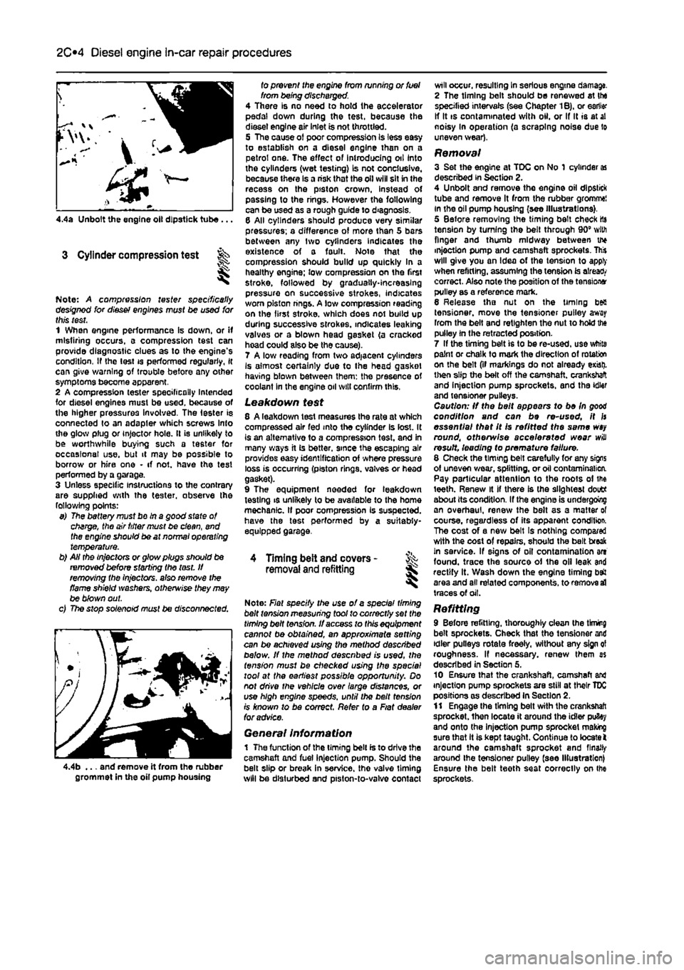
4.4a Unbolt the engine oil dipstick tube...
3 Cylinder compression test
Note: A compression tester specifically designed for diesef engines must be used for this test. 1 When engine performance Is down, or if misfiring occurs, a compression test can provide diagnostic clues as to the engine's condition, If the lest is performed regularly, it can give warning of trouble before any other symptoms become apparent. 2 A compression tester specifically Intended for diesel engines must be used, because of the higher pressures involved. The Ie6ter is connected to an adapler which screws Into the glow plug or injector hole. It is unlikely to be worthwhile buying such a tester for occasional use. but it may be possible to borrow or hire one • if not. have the test performed by a garage. 3 Unless specific instructions to the contrary are supplied with the tester, observe the following points: 9) The battery must bo in a good state of charge, the air titter must be clean, end the engine should be at normal operating temperature. b) AH the in/actors or glow plugs should be removed before starting the lest. If removing the injectors, also remove the flame shield washers, otherwise they may be blown out. c) The stop solenoid must be disconnected.
4.4b ... and remove it from the rubber grommet in the oil pump housing
fo prevent the engine from running or fuel from being discharged. 4 There is no need to hold the accelerator pedal down during the test, because the diesel engine air inlet is not throttled. 5 The cause of poor compression Is less easy to establish on a diesel engine than on a petrol one. The effect of introducing oil into the cylinders (wet testing) Is not conclusive, because there is a risk that the oil will sit in the recess on the piston crown, instead of passing to the rings. However the following can be used as a rough guide to diagnosis. 6 All cylinders should produce very similar pressures; a difference of more than 5 bars between any two cylinders Indicates the existence of a fault. Note that the compression should build up quickly In a healthy engine; low compression on the first stroke, followed by gradually-increasing pressure on successive strokes, indicates worn piston rings. A low compression reading on the first stroke, which does not build up during successive strokes, indicates leaking valves or a blown head gasket (a cracked hoad could also be the cause). 7 A low reading from two adjacent cylinders Is almost certainly due to the head gasket having blown between them: the presence of coolant In the engine oil will confirm this,
Leakdown test 8 A leakdown test measures the rate at which compressed air fed into the cylinder Is lost. It is an alternative to a compression test, and in many ways it is better, since the escaping air provides easy identification of where pressure loss is occurring (piston rings, valves or head gasket). 9 The equipment needed for leakdown testing is unlikely to be available to the home mechanic. If poor compression Is suspected, have the test performed by a suitably-equipped garage.
4 Timing belt and covers -removal
and
refitting
Note: Fiat specify the use of a spec/a/ timing belt tension measuring tool to correctly set the timing belt tension. If access to this equipment cannot be obtained, an approximate setting can be achieved using the method described below. If the method described is used, the tension must be checked using the special tool at the earliest possible opportunity. Do not drive the vehicle over large distances, or use high engine speeds, until the belt fens/on rs known to be correct. Refer to a Fiat dealer for advice.
General Information 1 The function of the timing belt is to drive the camshaft and fuel injection pump. Should the belt slip or break in service, the valve timing will be disturbed and piston-to-valve contact
will occur, resulting In serious engine damage. 2 The timing bolt should be renewed at the specified intervals (see Chapter 1B), or earlier If It is contaminated with oil. or If It is at al noisy In operation (a scraping noise due to uneven wear),
Removal 3 Set the engine at TDC on No 1 cylinder
as
described in Section 2. 4 Unbolt and remove tho engine oil dipstick tube and remove It from the rubber gromme! in the oil pump housing (see illustrations), 5 Before removing the timing belt check rts tension by turning the belt through 90" with finger and thumb midway between u* injection pump and camshaft sprockets. This will give you an Idea of the tension to apply when refitting, assuming the tension is already correct. Also note the position of the tensions pulley as a reference mark. 6 Release tho nut on the timing bea tensioner, move the tensioner pulley away from the belt and retlghten the nut to hold the pulley in the retracted position. 7 If the timing belt is to be re-used, use white paint or chalk to mark the direction of rotation on the belt (if markings do not already exist), then slip the belt off the camshaft, crankshaft and injection pump sprockets, and the idler and tensioner pulleys. Caution: If the belt appears to be In good condition and can be re-used, it fs essential that It Is refitted the same
wsy
round, otherwise accelerated wear will result, leading fo premature failure. 8 Check the timing belt carefully for any signs of uneven wear, splitting, or oil contamination. Pay particular attention to the roots of the teeth. Renew it if there is the slightest doutt about its condition. If the engine is undergoing an overhaul, renew the belt as a matter of course, regardless of its apparent conditio*. The cost of a new belt Is nothing compa/ed with the cost of repairs, should the belt freak in service. If signs of oil contamination art found, trace the source of the oil leak and rectify It. Wash down the engine timing baft area and all related components, to remove
sd
traces of oil.
Refitting 9 Before refitting, thoroughly clean the tknmg belt sprockets. Check that the tensioner and idler pulleys rotate freely, without any sign ol roughness. If necessary, renew them as described in Section 5. 10 Ensure that the crankshaft, camshaft and injection pump sprockets are still at their TDC positions as described In Section 2. 11 Engage the timing belt with the crankshaft sprocket, then locate it around the idler pufiey and onto the Injection pump sprocket making sure that it is kept taught. Continue to locate! around the camshaft sprocket and finally around Ihe tensioner pulley (see Illustration) Ensure the belt teeth seat correctly on Ihe sprockets.
Page 91 of 225

2D*10 Engine removal and overhaul procedures
1 General information
Included In (his Part of Chapter 2 are details of removing the engine/transmission from the car and general overhaul procedures for tho cylinder head, cylinder block/crankca9e and all other engine internal components. The information given ranges from advice concerning preparation for an overhaul and the purchase of replacement parts, to detailed step-by-step procedures covering removal, inspection, renovation and refitting of engine Internal components. After Section 5, all instructions are based on the assumption that the engine has been removed from the car. For Information concerning in-car engine repair, as well as the removal and refitting of those external components necessary for full overhaul, refer to Part A, 8 or C of this Chapter (as applicable) and to Section 5. Ignore any preliminary dismantling operations described in Part A. B or C that are no longer relevant onca the engine has been removed from ihe car.
2 Engine overhaul -general information
1 It Is not always easy to determine when, or if, an engine should be completely overhauled, as a number of lectors must be considered. 2 High mileage Is not necessarily an Indication that an overhaul Is needed, while low mileage does not preclude the need for an overhaul. Frequency of servicing Is probably the most important consideration. An engine which has had regular and frequent oil and filter changes, as well as other required maintenance, should give many thousands of miles of reliable service. Conversely, a neglected engine may require an overhaul very early In its life. 3 Excessive oil consumption Is an Indication that piston rings, vaivo seals and/or valve guides are in need of attention. Make sure that oil leaks are not responsible before deciding that the rings and/or guides are worn Perform a compression test, as described In Parts A or B (petrol engines) or C (diesel engines) of this Chapter, to determine the likely cause of the problem. 4 Check the oil pressure with a gauge fitted In place of the oil pressure switch. If it Is extremely low. the main and big-end bearings, and/or the oil pump, are probably worn out. 5 Loss of power, rough running, knocking or metallic engine noises, excessive valve gear noise, and high fuel consumption may also point to Ihe need for an overhaul, especially if
they are all present at the same time. If a complete service does not remedy the situation, major mechanical work is the only solution. 6 An engine overhaul involves restoring ell Internal parts to the specification of a new engine. During an overhaul, the cylinders are rebored (where applicable), the pistons and the piston rings are renewed. New main and big-end bearings are generally fitted; If necessary, the crankshaft may be reground. to restore the journals. 7 The valves are also servrced as well, since they are usually In less-than-perfect condition at this point. While the engine is being overhauled, other components, such as the starter and alternator, can be overhauled as well. The end result should be an as-new engine that will give many trouble-free miles. Note: Critical cooling system components such as the hoses, thermostat and coolant pump should be renewed when an engine is overhauled. The radiator should be checked carefully, to ensure that it is not clogged or leaking. A/so. it Is a good Idea to renew the ofI pump whenever the engine i$ overhauled.
8 Before beginning the engine overhaul, read through tho entire procedure, to familiarise yourself with the scope and requirements of the job. Overhauling an engine is not difficult If you follow carefully all of the instructions, have the necessary tools and equipment, and pay close attention to all specifications. It can, however, be time-consuming. Plan on the car being off the road for a minimum of two weeks, especially If pans must be taken to an engineering wo'kd for repair or reconditioning.
9 Check on the availability of parts and make sure that any necessary special tools and equipment are obtained in advance. Most work can be done with typical hand lools, although a number of precision measuring tools are required (or Inspecting parts to determine if they must be renewed. Often the engineering works will handle the inspection of parts and offer advice concerning reconditioning and renewal, Note: Always wait unt'l the engine has been completely dismantled, and until all components (especially the cylinder block/crankcase and the crankshaft) have been inspected, before deciding what service and repair operations must be performed by an engineering works. The condition of these components will be the major factor to consider when determining whether to overhaul the original engine, or to buy a reconditioned unit. Do not. fh ere tore, purchase parts or have overhaul work done on other components until they have been thoroughly Inspected. As a general rule, time is the primary cost of an overhaul, so it does not pay to fit worn or sub-standard parts.
10 As a final note, to ensure maximum life and minimum trouble from a reconditioned engine, everything must be assembled wilh care, in a spotlessly-clean environment.
3 Engine and transmission removal -methods
and
precautions
1 If you have decided that the engine must be removed for overhaul or major repair work, several preliminary steps should be taken. 2 Locating a suitable place to work is extremely important. Adequate work space, along with storage space for the car, will be needed. If a workshop or garage Is not available, at the very least, a flat, level, clean work surface Is required. 3 Cleaning the engine compartment and engine/transmission before beginning the removal procedure wilt help keep tools clean and organised. 4 An engine hoist or A-frame will also be necessary. Make sure the equipment is rated In excess of the combined weight of the engine and transmission, Safety Ib of primary Importance, considering the potential hazards involved in lifting the engine/transmission out of the car. 5 If this is Ihe first time you have removed
an
engine, an assistant Bhould Ideally be available. Advice and aid from someone more experienced would also be helpful. There are many instances when one person cannot simultaneously perform all of the operations required when lifting the engine out of Ihe vehicle. 6 Plan the operation ahead of time. Before starting work, arrange for the hire of or obtain all of the tools and equipment you will need. Some of the equipment necessary to perform engine/transmission removal and Installation safely and wilh relative ease On addition to an engine hoist) Is as follows: a heavy duly trolley jack, complete sets of spanners and sockets as described in the reference section of this manual, wooden blocks, and plenty of rags and cleaning solvent for mopping up spitted oil, coolant and fuel. If the hoist must be hired, make sure that you arrange for it In advance, and perform all of the operations possible without it beforehand. This will save you money and time.
7 Plan for the car to be out of use for quite a while. An engineering works will be required to perform some of the work which the do-it-yourselfer cannot accomplish without special equipment. These places often have a busy schedule, so it would be a good idea to consul! them before removing the engine, in order to accurately estimate the amount of time required to rebuild or repair components that may need work, 9 Always be extremely careful when removing and refitting the engine/transmission. Serious injury can result from careless actions. Plan ahead and take your time, and a job of this nature, although major, can be accomplished successfully.
Page 154 of 225

5B*2 Ignition system - petrol models
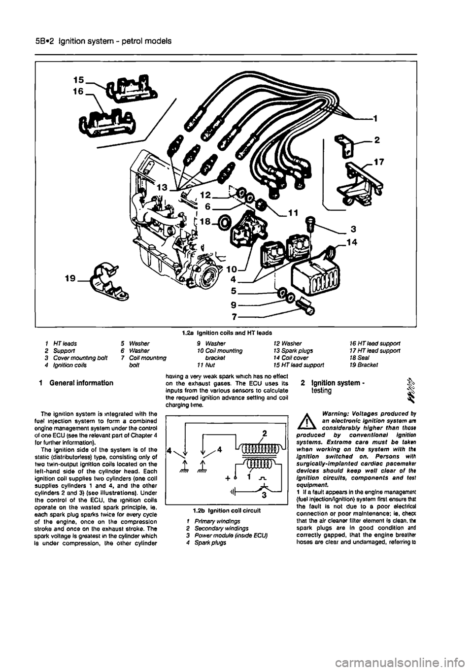
1 HT leads 2 Support 3 Cover mounting bdt 4 Ignition coifs
5 Washer 6 Washer 7 Coil mounting bolt
1.2s Ignition coils and HT leads 9 Washer 10 Coil mounting bracket
11
Nut
12 Waslrer 13 Spark plugs 14 Coll cover 15 HT lead support
16 HT lead support 17HTlead support 18 Seat Id Bracket
1 General information
The ignition system is integrated with the fuel injection system to form a combined engine management system under the control of one ECU (see the relevant part of Chapter 4 lor further Information). The Ignition side of the system is of the static (distributorless) type, consisting only of two twin-output Ignition coils located on the left-hand side of the cylinder head. Each ignition coil supplies two cylinders (one coll supplies cylinders 1 and 4, and the other cylinders 2 and 3) (see Illustrations). Under the control of the ECU, the ignition coils operate on the wasted spark principle, ie. each spark plug sparks twice for every cycle of the engine, once on the compression stroke and once on tho exhaust stroke. The spark voltage is greatest in the cylinder which Is under compression, the other cylinder
having a very weak spark which has no effect on the exhaust gases. The ECU uses Its Inputs from the various sensors to calculate the required ignition advance setting and coil chorging time.
1.2b Ignition coll circuit 1 Primary windings 2 Secondary windings 3 Power module
2 Ignition system -testing i
A
Warning: Voltages produced
by
an electronic Ignition system an considerably higher than (hose produced by conventional Ignition systems. Extreme care must be tak»n when working on tho system with thi Ignition switched on. Persons wilfl surgically-implanted cardiac pacemaker devices should keep well clear ot the ignition circuits, components and (oaf equipment 1 If a fault appears In the engine management (fuel injection/ignition) system first ensure that the fault is not due to a poor electrical connection or poor maintenance: ie, checK lhat the air cleaner filter element is clean, tht spark plugs are In good condition and correctly gapped, lhat the engine breather hoses are clear and undamaged, referring to
Page 155 of 225

Ignition system - petrol models 5B®3
Chapter 1A tor further information. Also check tnat tha accelerator cable is correctly adjusted
as
described in the relevant part of Chapter 4. If the engine is running very roughly, check the compression pressures and the valve clearances as descnbed In the relevant parts of Chapters 1 and 2. 2
H
these checks fall to reveal the cause of the problem, the vehicle should be taken to a suitably equipped Fiat dealer for testing. A wiring block connector Is Incorporated in the engine management circuit Into which a special electronic diagnostic tester can be plugged. The tester will locate the fault quickly and simply alleviating the need to test all the system components Individually which is a time consuming operation that carries a high risk of damaging the ECU. 3 The only Ignition system checks which can
oe
earned out by the home mechanic are those cescribed in Chapter 1A, relating to the spark plugs, and the ignition coll test descnbed In this Chapter. If necessary, the system wiring and wiring connectors can oe checked as descnbed in Chapter 12, Section 2, ensuring that the ECU wiring connector(s) have first
been
disconnected.
3 Ignition HT coil - ^ removal, testing and refitting
Removal 1 On 6-valve engines, unscrew the boll and remove the plastic cover from the left-hand
end
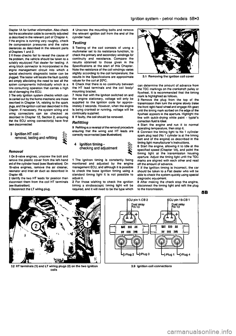
of the cylinder head (see Illustration). On 15-valve engines, remove the air cleaner, resonator and Inlet air duct as described in Chapter 4B. 2 Identify the two HT leads for position then disconnect them from the coil HT terminals jsee illustration). 3 Disconnect the LT wiring plug.
4 Unscrew the mounting bolts and remove the relevant ignition coil from the end of the cylinder head,
Testing 5 Testing of the coil consists of using a multimeter set to its resistance function, to check the primary and secondary windings for continuity and resistance. Compare the results obtained to those given In the Specifications at the start of this Chapter. Note the resistance of the coil windings varies slightly according to the coil temperature; the results In the Specifications are approximate values for the coil at 20°C. 6 Check that there is no continuity between the HT lead terminals and the coil body/ mourning bracket. 7 Note that with the ignition switched on and the engine stationary, voltage will only be supplied to the ignition cotls for approx-imately 2 seconds. However, when tho engine is being cranked or running, voltage will be continually supplied. 8 If faulty, the coil should be renewed.
Refitting 9 Refitting ts a reversal of the removal procedure ensuring that the winng and HT leads are correctly reconnected (see illustration).
4 ignition timing • checking and adjustment
1 The Ignition timing is constantly being monitored and adjusted by the engine management ECU, and although it is possible to check the base ignition liming using a standard timing light It is not possible to adjust it. 2 For those wishing to check the ignition timing a stroboscope timing light will be required, and it will need to be the type which
3.1 Removing the ignition coll cover
can determine the amount of advance from the TDC markings on the crankshaft pulley or flywheel. It Is recommended that the timing mark is highlighted as follows. 3 Remove the plug from the top of the transmission then turn tho engine slowly (raise the front right-hand wheel and engage 4th gear) until the timing mark scribed on the edge of the flywheel appears in the aperture. Highlight the line with quick-drying white paint - typist's correction fluid is ideal. 4 Start the engine and run It to normal operating temperature, then stop it. 5 Connect the timing light to No 1 cylinder spark plug lead (No 1 cylinder Is at the timing belt end of the engine) as described in the timing light manufacturer's Instructions. 6 Start the engine, allowing it to idle at the specified speed (Chapter 1A), and point the timing light at the transmission housing aperture. Adjust the timing light until the TDC marks are aligned with each other and read off the amount of advance. 7 If the ignition timing is incorrect, the car should be taken to a Fiat dealer who will be able to check the system quickly using special diagnostic equipment. 8 After making the check stop the engine, disconnect the timing light and refit the plug to the transmission.
3.2 HT terminals (1) and LT wiring plugs (2) on the two ignition colls 3.9 Ignition colt connections