compression ratio FIAT PUNTO 1995 176 / 1.G Workshop Manual
[x] Cancel search | Manufacturer: FIAT, Model Year: 1995, Model line: PUNTO, Model: FIAT PUNTO 1995 176 / 1.GPages: 225, PDF Size: 18.54 MB
Page 25 of 225
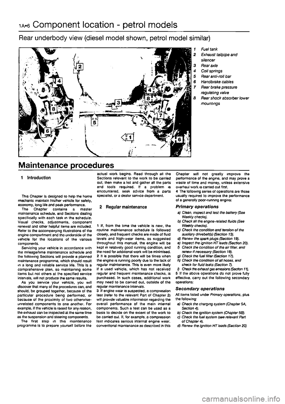
ia«6 Component location - petrol models
Rear underbody view (diesel model shown, petrol model similar)
1 Fuel
tank
2
Exhaust
tailpipe
and
silencer 3
Rear axle
4 Coll
springs
5
Rear
anti-mil
bar
6
Handbrake cables
T
Rear brake pressure
regulating
valve
S
Rear
shock absorber lower mountings
Maintenance procedures
1 Introduction
This Chapter is designed to help the home mechanic maintain his/her vehicle (or safety, eoonomy, long life and peak performance. The Chapter contains a master maintenance schedule, and Sections dealing specifically with each task in the schedule. Visual checks. ad}ustments, component renewal and other helpful Items are included. Refer to the accompanying Illustrations of the engine compartment and tho underside of the vehicle for the locations of the various components. Servicing your vehicle in accordance with ihe mlleaget/time maintenance schedule and the following Sections will provide a planned maintenance programme, which should result m a long and reliable service life. This Is a comprehensive plan, so maintaining some Items but not others at the specified service Intervals, will not produce the same results. As you service your vehicle, you will discover that many of the procedures can, and should, be grouped together, because of the particular procedure being performed, or because of the proximity of two otherwise-unrelated components to one another. For example, if the vehicle Is raised for any reason, the exhaust can be inspected at the same time as the suspension and steering components. The first step in this maintenance programme is to prepare yoursell before tne
actual work begins. Read through all the Sections relevant to the work to be carried out, then make a list and gather all the parts and tools required. If a problem is encountered, seek advice from a parts specialist, or a dealer service department.
2 Regular maintenance
1 If. from the time the vehicle is new, the routine maintenance schedule is followed closely, and frequent checks are made of fluid levels and high-wear items, as suggested throughout this manual, the engine will be kept in relatively good running condition, and the need for additional work will be minimised. 2 II is possible that there will be times when the engine rs running poorly due to the lack of regular maintenance. This is even more likely If a used vehicle, which has not received regular and frequent maintenance checks, is purchased. In such cases, additional work may need to be carried out. outside of the regular maintenance intervals. 3 If engine wear is suspected, a compression test (refer to the relevant Part of Chapter 2) will provide valuable information regarding the overall performance of the main internal components. Such a test can be used as a basis to decide on the extent of the work to bo carried out. II, for example, a compression test indicates serious internal engine wear, conventional maintenance as described in this
Chapter will not greatly improve the performance of the engine, and may prove a waste of time and money, unless extensive overhaul work is carried out first. 4 The following series of operations are those usually required to improve the performance of a generally poor-running engine:
Primary operations a) Cloan, inspect and test the battery
(See
Weekly checks), b) Check alt the engine-related fluids (See Weekly checks). c) Check the condition and tension of the auxiliary drivebeft($) (Section 13). d) Renew the spark plugs (Section 19). e) Inspect the ignition HT leads (Section 20). 0 Check the condition of the air filter, and renew if necessary (Section 18). g) Check the fuel filter (Section 17). h) Check tho condition of ell hoses, and check for fluid leaks (Sect/on 7). i) Check theexhaust
gas emissions (Section 11).
5 If the above operations do not prove fully effective, carry out the following secondary operations;
Secondary operations All items listed under Primary operations, plus the following; e) Check the charging system (Chapter 5K Section 4). b) Check the ignition system (Chapter 58). c) Check tho fuel system (see relevant Part of Chapter
4).
d) Renew the ignition HT leads (Section 20)
Page 41 of 225
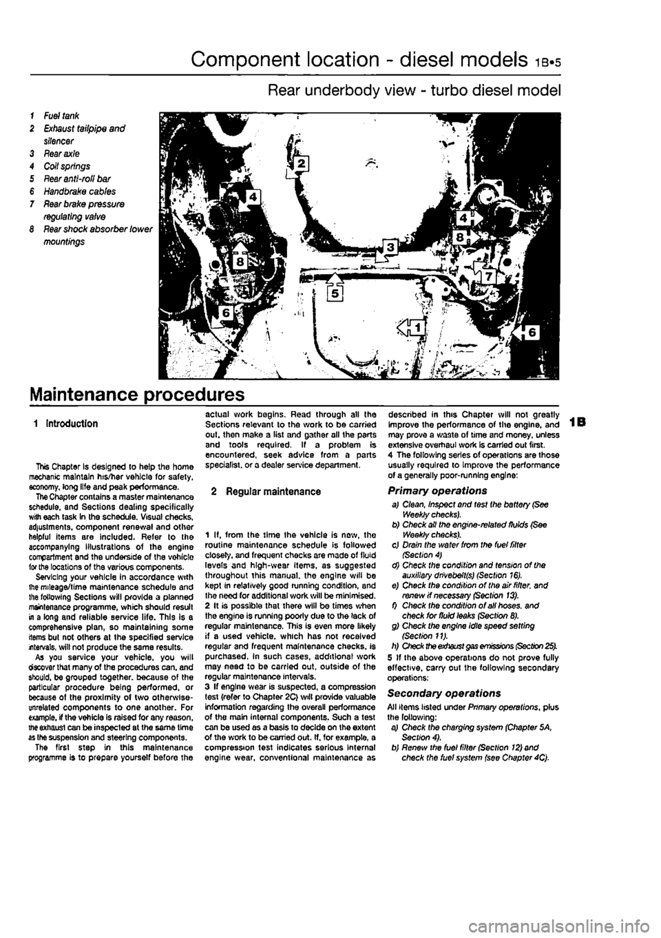
Component location - diesel models ib-s
Rear underbody view - turbo diesel model
1
Fuel tank
2
Exhaust
tailpipe
and
silencer 3 Fear axle 4 Coil springs 5
Rear anti-roll bar
€
Handbrake cables
7
Rear brake pressure regulating valve
8
Rear shock
absorber
lower
mountings
Maintenance procedures
1 Introduction
This Chapter Is designed to help the home mechanic maintain his/her vehicle for safety, economy, long life and peak performance. The Chapter contains a master maintenance schedule, and Sections dealing specifically with each task in the schedule. Visual checks, adjustments, component renewal and other helpful items are included. Refer to the accompanying illustrations of the engine compartment and the underside of the vohicle for the locations of the various components. Servicing your vehicle in accordance with ihe mileage/time maintenance schedule and the following Sections will provide a planned maintenance programme, which should result in a long and reliable service life. This is a comprehensive plan, so maintaining some items but not others at the specified service internals, will not produce the same results. As you service your vehicle, you will ctecover that many of the procedures can. and should, be grouped together, because of the particular procedure being performed, or because of the proximity of two otherwise-unrelated components to one another. For example, if the vehicle is raised for any reason, the exhaust can be inspected at the same time as the suspension and steering components. The first step in this maintenance programme is to prepare yoursetf before the
actual work begins. Read through all the Sections relevant to the work to be carried out. then make a list and gather all the parts and tools required. If a problem is encountered, seek advice from a parts specialist, or a dealer service department.
2 Regular maintenance
1 If, from the time Ihe vehicle is new, the routine maintenance schedule is followed closely, and frequent checks are made of fluid levels and high-wear Items, as suggested throughout this manual, the engine wifl be kept in relatively good running condition, and the need for additional work will be minimised. 2 It is possible that there will be times when the engine is running poorly due to the lack of regular maintenance. This is even more likely if a used vehicle, which has not received regular and frequent maintenance checks, is purchased, in such cases, additions! work may need to be carried out, outside of the regular maintenance intervals. 3 If engine wear is suspected, a compression test {refer to Chapter 2C} will provide valuable information regarding the overall performance of the main internal components. Such a test can be used as a basis to decide on the extent of the work to be carried out. If, for example, a compression test indicates serious Internal engine wear, conventional maintenance as
described in this Chapter will not greatly improve the performance of the engine, and may prove a wa3te of time and money, unless extensive overhaul work Is carried out first. 4 The following series of operations are those usually required to Improve the performance of a generally poor-running engine:
Primary operations a,I Clean, Inspect and test the battery (See Weekly checks). b) Check all the engine-related fluids (See Weekly checks). c) Drain the water from the fuel filter (Section 4) d) Check the condition and tension of the auxiliary dnvebeft(s) (Section 16). e) Check the condition of the air fitter, and renew if necessary (Section 13). f) Check the condition of all hoses, and check for fluid leaks (Section 8). g) Check the engine idle speed setting {Section 11). h) Check the exhaust gas emissions (Section 25). 5 If the above operations do not prove fully effective, carry out the following secondary operations:
Secondary operations All items listed under Pnmary operations, plus the following: a) Check the charging system (Chapter 5A, Section 4). b) Renew the fuel filter (Section 12) and check the fuel system (see Chapter 4Q.
Page 51 of 225
2A«1
Chapter 2 Part A:
SOHC (8-valve) petrol
engine in-car repair procedures
Contents
Auxiliary drivebelts • removal and refitting See Chapter 1A Gamstaft cover - removal and refitting 6 Camshaft oil seal - renewal 7 Camshaft • removal and refitting See Chapter 20 Crankshaft oil seals - renewal 8 Cylinder compression test 3 Cylinder head - dismantling and overhaul See Chapter 20 Cylinder head - remove] and refitting 9 Engine mountings - Inspection and renewal 11 Engine oil and filter • renewal See Chapter 1A
Degrees of difficulty
Engine oil level check See Weekiy checks Flywheel/driveplate • removal, inspection and refitting 10 General Information 1 Location of TOC on No 1 cylinder 2 Oil pump and pick-up tube - removal, inspection and refitting 13 Sump • removal and refitting 12 Timing belt and covers • removal and refitting .. 4 Timing belt tensioner and sprockets - removal, inspection and refitting 5 Vafve clearance check and adjustment See Chapter 1A
Easy, suitable (or twics with little |g experience ^
Fairty easy, suitable jk for beginner with & some experience ^
Fatrty difficult, ^ suitable for competent ^ CKYmechanic ^
Difficult, suitable for ^ experienced DIY « mechanic ^
Veiy difficult, ^ aiitabte for expert DIY « or professional
Specifications
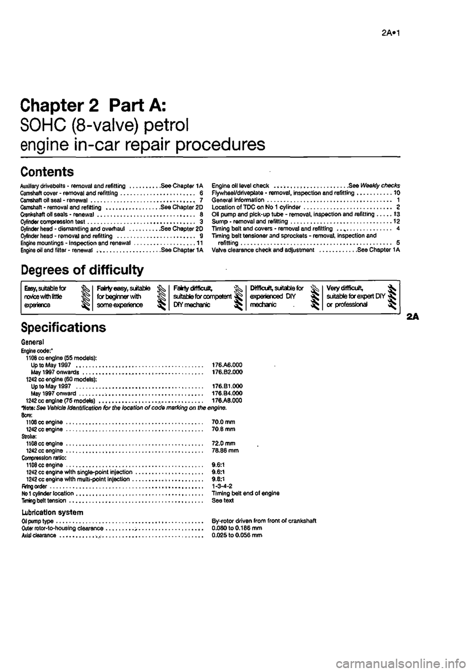
General Engine code:' 1108 cc engine (55 models): Up to May 1997 176.A6.000 May 1d97 onwards • . 176.B2.000 1242 cc engine (60 models): Up to May 1997 176.B1.000 May 1997 onward 176.B4.000 1242 cc engine (75 modete) 176.A8.000
•Note:
See Vehicle Identification for the location of code marking on the engine. 8cre: 11O0OC engine 70.0 mm 1242 cc engine 70.8 mm Stroke: 1108 cc engine 72.0 mm 1242 cc engine 78.86 mm Compression ratio: 1108 cc engine 9.6:1 1242 cc engine with single-point injection 9.6:1 1242 cc engine with multi-point injection 9.8:1 Rrlng order 1-3-4-2
No 1
cylinder location Timing belt end of engine
TnUng
belt tension See text
Lubrication system
Oil
pump type By-rotor driven from front of crankshaft Outer rotor-to-housing clearance 0.080to0.186mm
Axial
clearance 0.025 to 0.056 mm
Page 52 of 225
2A*10 SOHC (8-valve) petrol engine in-car repair procedures
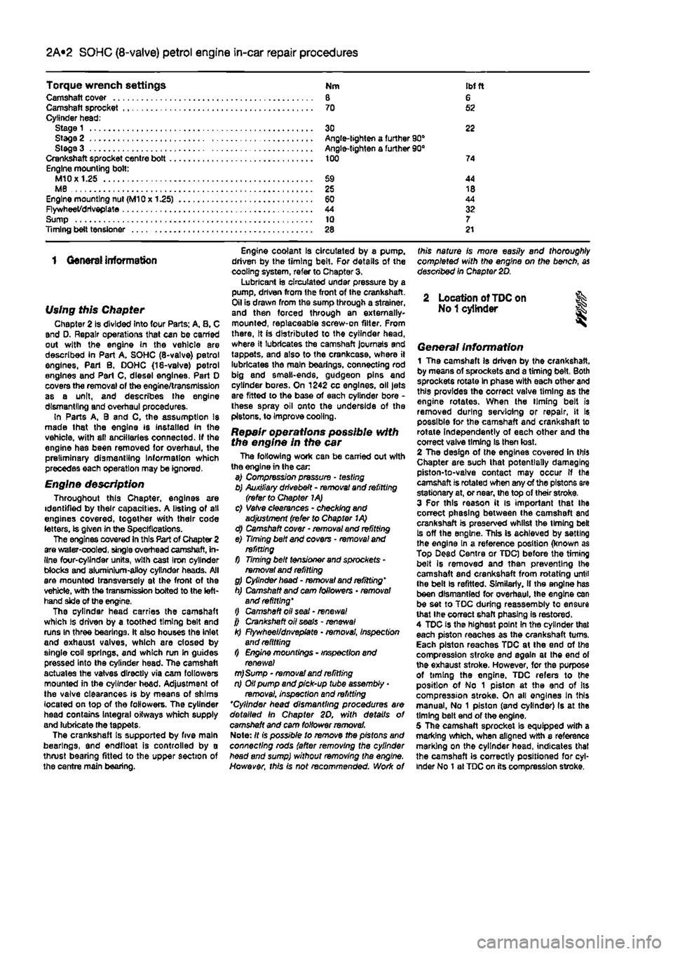
Torque wrench settings Nm
IM
ft Camshaft cover 8 6 Camshaft sprocket 70 52 Cylinder head; Stage 1 30 22 Stage 2 Angle-lighten a further 90° Siege 3 Angle-tighten a further 90B Crankshaft sprocket centre bott 100 74 Engine mounting bolt: M10X1.25 69 44 MB 25 18 Engine mounting nut (M10x 1.25) 60 44 Flywheet/driveplate 44 32 Sump 10 7 Timing belt tensJoner 28 21
1 General information
Using this Chapter Chapter 2 is divided Into four Parts: A. 8. C and D. Repair operations that can be carried out with the engine in the vehicle are described in Part A. SOHC (8-valve) petrol engines, Part B. DOHC (18-valve) petrol engines and Part C, diesel engines. Part 0 covers the removal of the engine/transmission as a unit, and describes the engine dismantling and overhaul procedures. In Parts A, 9 and C, the assumption Is made lhat the engine is Installed in the vehicle, with sll ancillaries connected. If the engine has been removed for overhaul, the preliminary dismantling Information which precedes each operation may be ignored.
Engine description Throughout this Chapter, engines are identified by their capacities. A listing of all engines covered, together with their code letters, is given in the Specifications. The engines covered In this Part of Chapter 2 are water-cooled, single overhead camshaft, in-line four-cylinder units, with cast Iron cylinder Mocks and aluminium-alloy cylinder heads. All are mounted transversely at the front ot the vehicle, with the transmission bolted to the left-hand side of the engine, The cylinder head carries the camshaft which is driven by a toothed timing belt and runs In three bearings. It also houses the inlet and exhaust valves, which are closed by single coil springs, and which run in guides pressed Into the cylinder head. The camshaft actuates the vatves directly via cam followers mounted in the cylinder head. Adjustment of the valve clearances is by means of shims located on top of the followers. The cylinder head contains Integral oitways which supply and lubricate the tappets. The crankshafl Is supported by five main bearings, and endftoat is controlled by a thrust bearing fitted to the upper section of the centre main bearing.
Engine coolant is circulated by 8 pump, driven by the timing belt. For details of the cooling system, refer to Chapter 3. Lubricant is circulated under pressure by a pump, driven from ihe front of the crankshaft. Oil Is drawn from the sump through a strainer, and then forced through an externally-mounted, replaceable screw-on filter. From there, It is distributed to the cylinder head, where It lubricates the camshaft journals and tappets, and also to the crankcase, where il lubricates the main bearings, connecting rod big and smell-ends, gudgeon pins and cylinder bores. On 1242 cc engines, oil jets are fitted lo the base of each cylinder bore -these spray oil onto the underside of the pistons, to Improve cooling.
Repair operations possible with the engine in the car The following work can be carried out with the engine in the car a) Compression pressure - testing b) Auxiliary drivebelt - removal and refitting (refer to Chapter 1A) c) Vatve clearances - checking and adjustment (refer to Chapter I A) d) Camshaft cover - removal and refitting e) Timing belt and covens - removal and refitting f) Timing belt tensioner and sprockets -removal and refitting g) Cylinder head - removal and refitting' h) Camshaft and cam followers • removal and refitting' t) Camshaft oil seal - renews/ j) Crankshaft oil seals - renewal k) Flywheel/dnvepfate • removal, inspection and refitting l) Engine mountings - inspection and renewal m)Sump - removal and refitting n) Oil pump and pick-up tube assembly
•
removai. inspection and refitting *Cylinder head dismantling procedures are detailed In Chapter SO, with details of camshaft and cam follower removal. Note: It is possible to remove the pistons and connecting rods (after removing the cylinder head and sump) without removing the engine. However, this is not recommended. Work of
this nature is more easily and thoroughly completed with the engine on the bench, as described In Chapter 2D.
2 Location of
TDC
on % No
1
cylinder
General Information 1 The camshaft Is driven by the crankshaft, by means of sprockets and a timing belt. Both sprockets rotate In phase with each other and this provides the correct valve timing as the engine rotates. When (he liming belt is removed during servioing or repair, it Is possible for the camshaft and crankshaft to rotate Independently of each other and the correct valve timing Is then lost. 2 The design of the engines covered In this Chapter are such lhat potentially damaging piston-to-valve contact may occur if the camshaft is rotated when any of the pistons are stationary at, or near, the top of their stroke. 3 For this reason it is important lhat Ihe correct phasing between the camshaft and crankshaft is preserved whilst the timing belt Is off the engine. This is achieved by setting the engine In a reference position (known as Top Dead Centre or TDC) before the timing belt Is removed and then preventing the camshaft and crankshaft from rotating until the belt is refitted. Similarly, if ths engine has been dismantled for overhaul, the engine can be set to TOC during reassembly to ensure that Ihe correct shaft phasing is restored. 4 TDC is the highest point In the cylinder that each piston reaches as the crankshaft turns. Each piston reaches TDC at Ihe end of the compression stroke and again at the end of the exhaust stroke. However, for the purpose of timing the ongine. TDC refers to the position of No 1 piston at the end of Its compression stroke. On ail engines In this manual, No 1 piston (and cylinder) Is at the timing belt end of the engine. 5 The camshaft sprocket Is equipped with a marking which, when aligned with a reference marking on the cylinder head, indicates that the camshaft is correctly positioned for cyl-inder No 1 al TDC on its compression stroke.
Page 53 of 225
2A*10 SOHC (8-valve) petrol engine in-car repair procedures
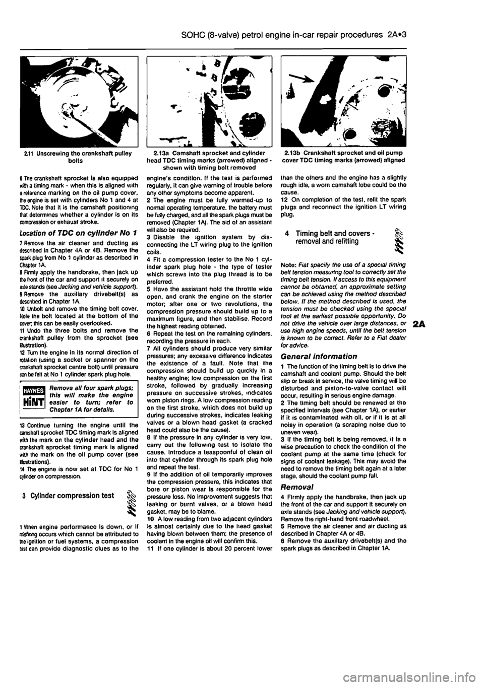
2.11 Unscrewing the crankshaft pulley bolts
6 Itae crankshaft sprocket Is also equipped •nth a timing mark - when this is aligned with 3relarence marking on the oil pump cover.
Hie
engine is set with cylinders No 1 and 4 at
TDC.
Note that it is the camshaft positioning that determines whether a cylinder is on its comcression or exhaust stroke.
Location
of TDC on cylinder No 1 7 Remove the air cleaner and ducting as descnbed in Chapter 4A or 4B. Remove the
spark
plug from No 1 cylinder as described in Chapter 1A. 8 Firmly apply the handbrake, then |ack up
the
front of the car and support it securely on iiia stands (see Jacking end vehicle support). 9 Remove the auxiliary drivebelt(s) as described in Chapter 1A. 10 Unbolt and remove the timing belt cover. Mole the bolt located at the bottom of the
coven
this can be easily overlooked. 11 Undo the three bolts and remove the crankshaft pulley from the sprocket (see {lustration). 12 Turn Ihe engine in its normal direction of rotation (using a socket or spanner on Ihe crankshaft sprocket centre bolt) until pressure an be felt at No
1
cylinder spark plug hole.
1 flfliyflg^ Remove all four spark plugs; "••"•1 this will make the engine HlNTl easier to turn; refer to Chapter 1A for details.
13 Continue turning the engine until the crahaft sprocket TDC timing mark is aligned with the mark on the cylinder head and the crankshaft sprocket timing mark is aligned with the mark on the oil pump cover (see ilustrations). 14 The engine is now set at TDC for No 1 cylinder on compression.
3 Cylinder compression test t ^
1 When engine performance Is down, or if misfiring occurs which cannot be attributed to tne ignition or fuei systems, a compression isst can provide diagnostic clues as to the
2.13a Camshaft sprocket and cylinder head TDC timing marks (arrowed) aligned -shown with timing belt removed engine's condition. II the test is performed regularly, it can give warning of trouble any other symptoms become apparent. 2 The engine must be fully warmed-up to normal operating temperature, the battery must be fufly charged, and all the spark plugs must be removed (Chapter 1A). The aid of an assistant will also be required. 3 Disable the ignition system by dis-connecting the LT wiring plug to the ignition coils. 4 Fit a compression tester to the No 1 cyl-inder spark plug hole - the type of tester which screws into the plug thread is to be preferred, 5 Have the assistant hold the throttle wide open, and crank the engine on the starter motor; after one or two revolutions, the compression pressure should build up to a maximum figure, and then stabilise. Record the highest reading obtained. 6 Repeat the lest on the remaining cylinders, recording the pressure in each. 7 All cylinders should produce very similar pressures; any excessive difference indicates the existence of a fault. Note that the compression should build up quickly in a healthy engine; low compression on the first stroke, followed by gradually increasing pressure on successive strokes, indicates worn piston rings. A low compression reading on the first stroke, which does not build up during successive strokes, indicates leaking valves or a blown head gasket (a cracked head could also be the cause). 8 If the pressure in any cylinder is very low. carry out the following test to isolate the cause. Introduce a teaspoonful of clean oil into that cylinder through its spark plug hole and repeat the test. 9 If the addition of oil temporarily improves the compression pressure, this indicates that bore or piston wear Is responsible for the pressure loss. No improvement suggests that leaking or burnt valves, or a biown head gasket, may be to blame. 10 A low reading from two adjacent cylinders is almost certainly due to the head gasket having blown between them; the presence of coolant in the engine oil will confirm this. 11 If one cylinder is about 20 percent lower
2.13b Crankshaft sprocket and oil pump cover TDC timing marks (arrowed) aligned
than the others and Ihe engine has a slightly rough idle, a worn camshaft lobe could be the cause. 12 On completion of the test, refit the spark plugs and reconnect the ignition LT wiring plug.
4 Timing belt and covers -removal and refitting ^
Note: Fiat specify the use of a special timing belt fens/on measuring toot to correctly set tho timing belt tension. If access to this equipment cannot be obtained, an approximate setting can be achieved using the method described below. It the method described is used, the tension must be checked using the special tool at the earliest possible opportunity. Do not drive the vehicle over large distances, or use high engine speeds, until the belt tension is known fo be correct. Refer to a Fiat dealer foradvSce.
General information 1 The function of the timing belt is to drive Ihe camshaft and coolant pump. Should the belt slip or break In service, the valve timing will be disturbed and piston-to-valvo contact will occur, resulting in serious engine damage, 2 The timing belt should be renewed ai the specified intervals (see Chapter 1A), or earlier if it is contaminated with oil. or if it is at all noisy in operation (a scraping noise due to uneven wear). 3 If the timing belt is being removed, it Is a wise precaution to check the condition of the coolant pump at the same time (check for signs of coolant leakage). This may avoid the need to remove the timing belt again at a later stage, should the coolant pump fall.
Removal 4 Firmly apply the handbrake, then jack up the front of the car and support it securely on axle stands (see Jacking and vehicle support). Remove the right-hand front road wheel. 5 Remove the air cleaner and air ducting as described in Chapter 4A or 46. 6 Remove the auxiliary drivebelt(s) and the spark plugs as described in Chapter 1A.
2A
Page 61 of 225
2B»1
Chapter 2 Part B:
DOHC (16-valve) petrol
engine in-car repair procedures
Contents
Auxiliary drlvebelts - removal and refitting See Chapter 1A Camshaft oil seal - renewal 6 Camshafts and cam followers - removal, inspection and refitting .. 9 Crankshaft oil seals • renewal 7 Cylinder compression test 3 Cylinder head - dismantling and overhaul See Chapter 2D Cylinder head • removal and refitting 10 Cylinder head extension • removal and refitting 8 Engine assembly/Valve timing holes - general information and usage 2
Engine mountings - inspection and renewal 12 Engine oil and filter - renewal See Chapter 1A Engine oil level - check See Weekly checks Flywheel - removal, Inspection and refitting 11 General Information 1 Oil pump and pick-up tube - removal, inspection and refitting 14 Sump - removal and refitting 13 Timing belt and covers - removal and refitting 4 Timing belt tensioner and sprockets • removal and refitting 5
Degrees of difficulty
Easy,
sitable
for
J; Fairly
easy,
suitable Fairtydifflcutt, ^
Difficult,
aitabtefcr Very
difficult,
^ nwice
wim
(ttls for beginner with £
suitable
for competent KYmechanic ^ experienced DIY > suitable
for
expert DIY« experience
some
experience £
suitable
for competent KYmechanic ^ mechanic > or professional ^
Specifications
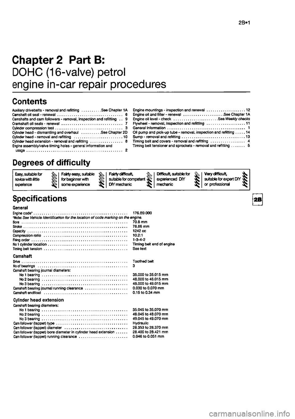
General Engine code* 176.09.000 •Note: See Vehicle Identification for the location of code marking on the engine. Bore 70.8 mm Stroke 78.86 mm Capacity 1242 cc Compression ratio 10.2:1 Firing order 1-3-4-2 No
1
cylinder location Timing belt end of engine Timing belt tension See text
Camshaft Orlve Toothed belt
No
of bearings 3 Camshaft bearing journal diameters: Ho
1
bearing 35.000 to 35.015 mm
Mo
2 bearing 48.000 to 48.015 mm No 3 bearing 49.000 to 49.015 mm Camshaft bearing Journal running clearance 0.030 to 0.070 mm Camshaft endfloat 0.15 to 0.34 mm
Cylinder head extension Camshaft bearing diamelers: No
1
bearing 35.045 to 35.070 mm No 2 bearing 48,045 to 48.070 mm No 3 bearing 49.045 to 49.070 mm
Cam
follower (tappet) type Hydraulic
Cam
follower (tappet) diameter 28.353 to 28.370 mm
Cam
follower (tappet) bore diameter in cylinder head extension 28.400 to 28.421 mm
Cam
follower (tappet) running clearance 0.046 to
0.051
mm
Page 64 of 225
2B*4 DOHC (16-valve) petrol engine in-car repair procedures
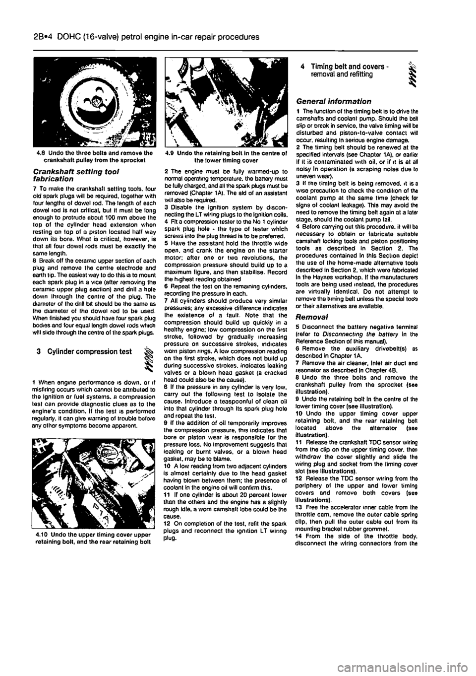
4.8 Undo three bolts and romove tho crankshaft pulley from the sprocket
Crankshaft setting toot fabrication 7 To make Ihe crankshafl setting tools, four old spark plugs will be required, together with four lengths of dowel rod. The length of each dowel rod is not critical, bul It must be long enough to protrude about 100 mm above the top of the cylinder head extension when resting on top of a piston located half way down its bore. What is critical, however, is that all four do wo I rods must be exactly the same length. 8 Break off the ceramic upper section of each plug and remove the centre electrode and earth tip. The easiest way to do this is to mount each spark plug in a vice (attar removing the ceramic uppor plug section) and drill a hole down through ihe centre of the plug. The diameter of Ihe drill bit should be the same as Ihe diameter of Ihe dowol rod to be used. When finished you should have four spark plug bodies and four equal length dowel rods which will slide through the centre of the spark plugs.
3 Cylinder compression test
1 When engine performance is down, or it misfiring occurs which cannot be attnbuted to the Ignition or fuel systems, a compression test can provide diagnostic clues as to the engine's condition. If the lest is performed regularly, it can give warning of trouble bofore any other symptoms become apparent.
4.10 Undo the upper timing cover upper retaining bolt, and the rear retaining boll
4.9 Undo the retaining bolt in the centre of the lower timing cover
2 The engine must be fully warmed-up to normal operxrtrfjg temperature, the battery must be fully charged, and all the spark plugs muse be removed (Chapter 1A>. The aid of an assistant wilt also be required. 3 Disable the ignition system by discon-necting the LT wiring plugs to the Ignition coils. 4 Fit a compression tester to the No t cylinder spark plug hole • the type of tester which screws into the plug thread is to be preferred. 5 Have the assistant hold the throttle wide open, and crank the engine on the starter motor; after one or two revolutions, the compression pressure should build up to a maximum figure, and then stabilise. Record the h.ghest reading obtained 6 Repeat the test on the remaining cylinders, recording Ihe pressure in each. 7 All cylinders should produce very similar pressures; any excessive difference indicates Ihe existence of a fault. Note that the compression should build up quickly in a healthy engine; low compression on (he first stroke, followed by gradually increasing pressure on successive strokes, indicates worn piston rings. A low compression reading on the first stroke, which does not build up during successive strokes, indicates leaking valves or a blown head gasket (a cracked head could also be tho cause). 6 If the pressure in any cylinder is very low, carry out the following test to isolate the cause. Introduce a teaspoonful of dean oil into that cylinder through its spark plug hole and repeal the lest. 9 If the addition of oil temporarily improves the compression pressure, this indicates that bore or piston wear is responsible for the pressure loss. No improvement suggests that leaking or burnt valves, or a blown head gasket, may be to blame. 10 A low reading from two adjacent cylinders is almost certainly due to the head gasket having blown between Ihem; the presence of coolant in the engine oil will confirm this. 11 If one cylinder is about 20 percent lower than the others and the engine has a slightly rough idle, a worn camshaft lobe could be the cause. 12 On completion of the test, refit the spark plugs and reconnect the ignition LT wiring plug.
4 Timing belt and covers -removal and refitting §
General information 1 The luncUon of the timing belt Is to drive the camshafts and coolant pump. Should the bell slip or creak in service, the valve timing will be disturbed and piston-to-valve contact wiu occur, resulting in serious engine damage. 2 The timing belt should be renewed at the specified Intervals (see Chapter 1A), or earlier If It is contaminated with oil, or if it is at all noisy In operation (a scraping noise due to uneven wear}. 3 If the timing belt is being removed, it is
a
wise precaution to check the condition of the coolam pump at the same time (oheck for signs of coolant leakage). This may avoid the need to remove the timing belt again at a later stage, should the coolant pump fail. 4 Before carrying out this procedure, it will be necessary to obtain or fabricate suitable camshaft locking tools and piston positioning tools as described in Section 2. The procedures contained In this Section depict the use of the home-made alternative tools described in Section 2. which were fabricated In the Haynes workshop. If the manufacturers tools are being used instead, the procedures are virtually identical. Oo not attempt to remove the timing bell unless the special totfs or their alternatives are available.
Removal 5 Disconnect the battery negative terminal (refer to Disconnecting the battery in the Reference Section of Ihis manual). 6 Remove the auxiliary drivebelt(s) as described In Chapter 1A. 7 Remove the air cleaner, Inlet air duct and resonator as desenbed In Chapter 4B. 8 Undo the three bolts and remove the crankshaft pulley from the sprocket (see illustration). 9 Undo the retaining bolt In the centre of the lower liming cover (see illustration). 10 Undo tho uppor timing cover upper retaining bolt, and the rear retaining bolt located above the alternator (see illustration). 11 Release the crankshaft TDC sensor wiring from the clip on the upper timing cover, then withdraw the cover slightly and slide Ihe wiring plug and socket from the liming cover slot (see illustrations). 12 Release the TDC sensor wiring from the periphery ol the upper and fower timing covers and remove both covers (see Illustrations). 13 Free the accelerator inner cable from the throttle cam, remove the outer cable spring dip, then pull the outer cable out from its mounting bracket rubber grommet. 14 From the side of the throttle body, disconnect the wiring connectors from the
Page 73 of 225
2C«1
Chapter 2 PartC:
Diesel engine in-car repair procedures
Contents
Auxiliary drivebelts - removal and refitting See Chapter 1B Camshaft cover - removal and refitting 6 Camshaft oil seal - renewal 7 Camshaft - removal and refitting See Chapter 20 Crankshaft oil seats - renewal 8 Cylinder compression test « 3 Cylinder head - dismantling and overhaul See Chapter 20 Cylinder head - removal and refitting 9 Engine mountings - inspection and renewal 11 Engine oil and fitter - renewal See Chapter 18 Engine oil level check See Weekly checks
Degrees of difficulty
Flywheel * removal, inspection and refitting 10 General information 1 Location of TDC on No 1 cylinder 2 Oil cooler - removal and refitting 14 Oil pump and pick-up tube • removal, Inspection and refitting 13 Sump • removal and refitting 12 Timing belt and covers • removal and refitting 4 Timing belt tensioner and sprockets - removal, Inspection and refitting 5 Valve clearance check and adjustment See Chapter 1B
Easy,
suitable for novice
with Irttle
|| experience g^
FaMy
eesy,
suitable ^
forbeglnnerwilti
some experience ^
Falrtydfficult, ^ suitable
for
competent DIYmechanic ^
Difficult, suitable
for & experienced DIY mechanic ^
Very
difficult,
^ suitable
for
expert
DfY
jR or professional ^
Specifications
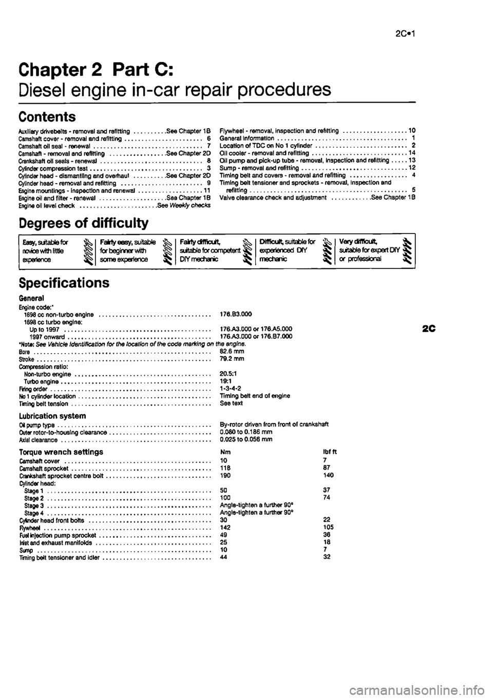
General Engine code:' 1698 cc non-turbo engine 176.B3.000 1698 cc turbo engine: Up to 1997 t76.A3.00aor176.A5.000 1997 onward 176.A3.000or176.B7.000 •Note: See Vehicle Identification for the location of the code marking on the engine. Bore 82.6 mm Stroke 79.2 mm Compression ratio: Non-turbo engine 20.5:1 Turbo engine 19:1 Firing order 1-3-4-2
No 1
cylinder location Timing belt end of engine Titling belt tension See text
Lubrication system Oi pump type By-rotor driven from front of crankshaft Outer rotor-to-houslng clearance 0.080 to 0.186 mm Axial clearance 0.025 to 0.056 mm
Torque wrench settings Nm ibf ft Camshaft cover 10 7 Camshaft sprocket 11B 87 Crankshaft sprocket centre bolt 190 140 Cylinder head: Stage 1 50 37 Stage 2 100 74 StageS Angle-tighten a furtfier 90" Stage 4 Angle-tighten a further 90° CySnder head front bolts 30 22 Flywheel 142 105
Fuel
injection pump sprocket 49 36 Inlet and exhaust manifolds 25 18 Sump 10 7 Timing belt tensioner and idler 44 32
Page 74 of 225
2C*2 Diesel engine in-car repair procedures
1 General information
Using this Chapter Chapter 2 is divided Into four Parts; A. 8, C and 0. Repair operations that cart be carried out with the engine in the vehicle are described In Part A, SOHC (B-valve) petrol engines. Part B, DOHC (16-valve) petrol engines and Part C. diesel engines, Part D covers the removal of the engine/transmission as a unit, and describes the engine dismantling and overhaul procedures. In Parts A. 8 and C. the assumption Is made that the engine is installed in Ihe vehicle, with all anciliaries connected If the engine has been removed for overhaul, the preliminary dismantling information which precedes each operation may be ignored.
Engine description Both normally aspirated (non-turbo) and turbocharged diesel engines are fitted to the Punto range. The engines together with their codes are given in the Specifications at the start of lhis Chapter. The engines are water-cooled, single-overhead camshaft. In-line lour cylinder units with cast-iron cylinder blocks and aluminium-alloy cylinder heads. The engine is mounted transversely at the front of the vehicle, with the transmission bolted to the left-hand side of the engine. The cylinder head carries the camshaft which is driven by a toothed timing belt. It also houses the inlet and exhaust valves which are closed by single coll valve springs and run in valve guides pressed into the cylinder head. The valves are operated by cam followers fitted over each valve, and the clearances are adjusted by shims positioned between the followers and the camshaft lobes. The camshaft is supported by four bearings • the end bearings are machined in the cylinder head and the remaining bearings have caps bolted to the cylinder head. The cylinder head contains integral oiiways which supply and lubricate the camshaft and followers and it also Incorporates renewable swirl chambers. The crankshaft Is supported by five main bearings, and endfloat Is controlled by a thrust bearing fitted on the rear main bearing. All diesel engines are fitted with a brake servo vacuum pump dnven from the left-hBnd end of the camshaft. Engine coolant is circulated by a pump, driven by the auxiliary drivebeit. For details of the cooling system refer to Chapter 3. Lubricant is circulated under pressure by a pump, driven from the front of the crankshaft. Oil is drawn from the sump through a strainer, and then forced through an externally-mounted, replaceable screw-on filter. From there, it is distributed to the cylinder head.
where il lubncates the camshaft journals and followers, and also to the crankcase, where it lubricates the main bearings, connecting rod big- and small-ends, gudgeon pins and cylinder bores. Oil jets are fitted to the base of each cylinder bore - these spray oil onto the underside of the pistons, lo Improve cooling. An oil cooler is also fitted to reduce the temp-erature of oil before it re-enters the engine.
Repair operations possible with the engine in the car The following work can be carried out with the engine in the can a) Compression pressure - testing b) Auxiliary drivebeit - removal and refitting (refer to Chapter rej c) Valve clearances • checking and adjustment (refer to Chapter 1B) d) Camshaft cover - removal and refitting e) Tim/ng belt and covers • removal and refitting 0 Timing belt tensioner and sprockets -removal and refitting g) Cylinder head - removal and refitting' h) Camshaft and cam followers - removal end refitting' I) Camshaft oil seal - renewal j) Crankshaft oil seals - renewal k) Flywheel • removal, inspection and refitting I) Engine mountings - inspection and renewal m)Sump • removal and refitting n) Oil pump and pick-up tube assembly -removal, inspection and refitting 'Cylinder head dismantling procedures are detalfed In Chapter 2D, with details of camshaft and cam follower removal. Note: It ts possible to remove the pistons and connecting rods (after removing the cylinder nead and sump) without removing the engine. However, this is not recommended. Work of this nature is more easily and thoroughly completed with the engine on tho bench as described in Chapter 2D.
2 Location of
TDC
on ^ No
1
cylinder ||
General information 1 The camshaft and fuel Injection pump are driven by the crankshaft, by means of sprockets and a timing belt. All three sprockets rotate in phase with each other and this provides the correct valve and injection pump timing as the engine rotates. When the timing bell is removed during servicing or repair, it is possible for the camshaft, injection pump and crankshaft to rotate independently of each other and the correct timing Is then lost.
2 It
Location of TDC on cylinder No
1
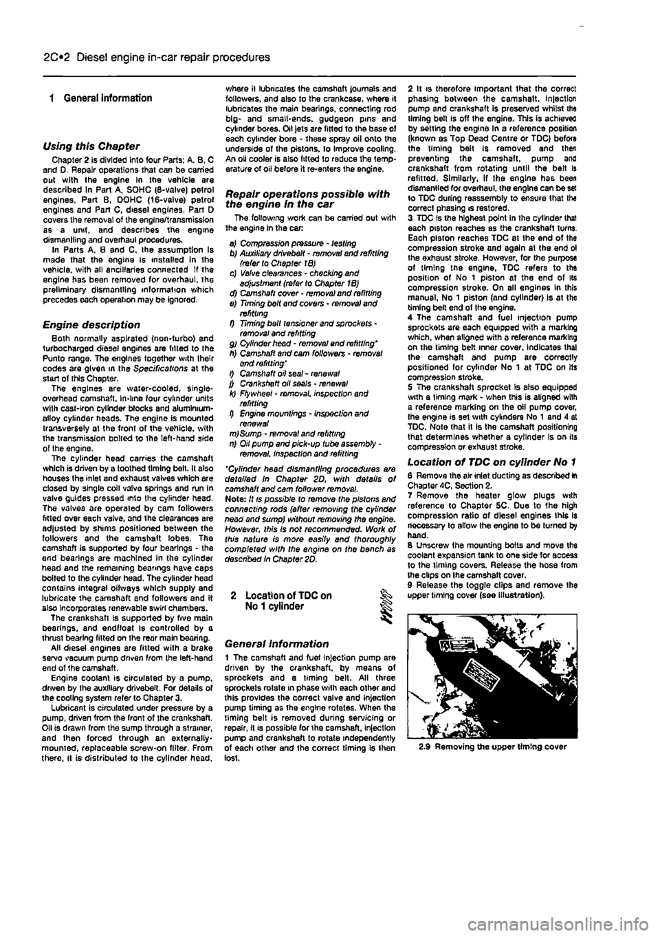
6 Remove the air inlet ducting as described ft Chapter 4C, Section 2. 7 Remove the heater glow plugs with reference to Chapter 5C. Due to the high compression ratio of diesel engines this Is necessary to allow the engine to be turned by hand. 8 Unscrew the mounting bolts and move the coolant expansion tank to one side for access to the timing covers. Release the hose from the clips on Ihe camshaft cover. 9 Release the toggle clips and remove the upper timing cover (see illustration),
2.9 Removing the upper timing cover
Page 75 of 225
Diesel engine in-car repair procedures
2C*11
10 firmly apply the handbrake, then jack up
Ihe
front of the car and support it securely on
arte stands
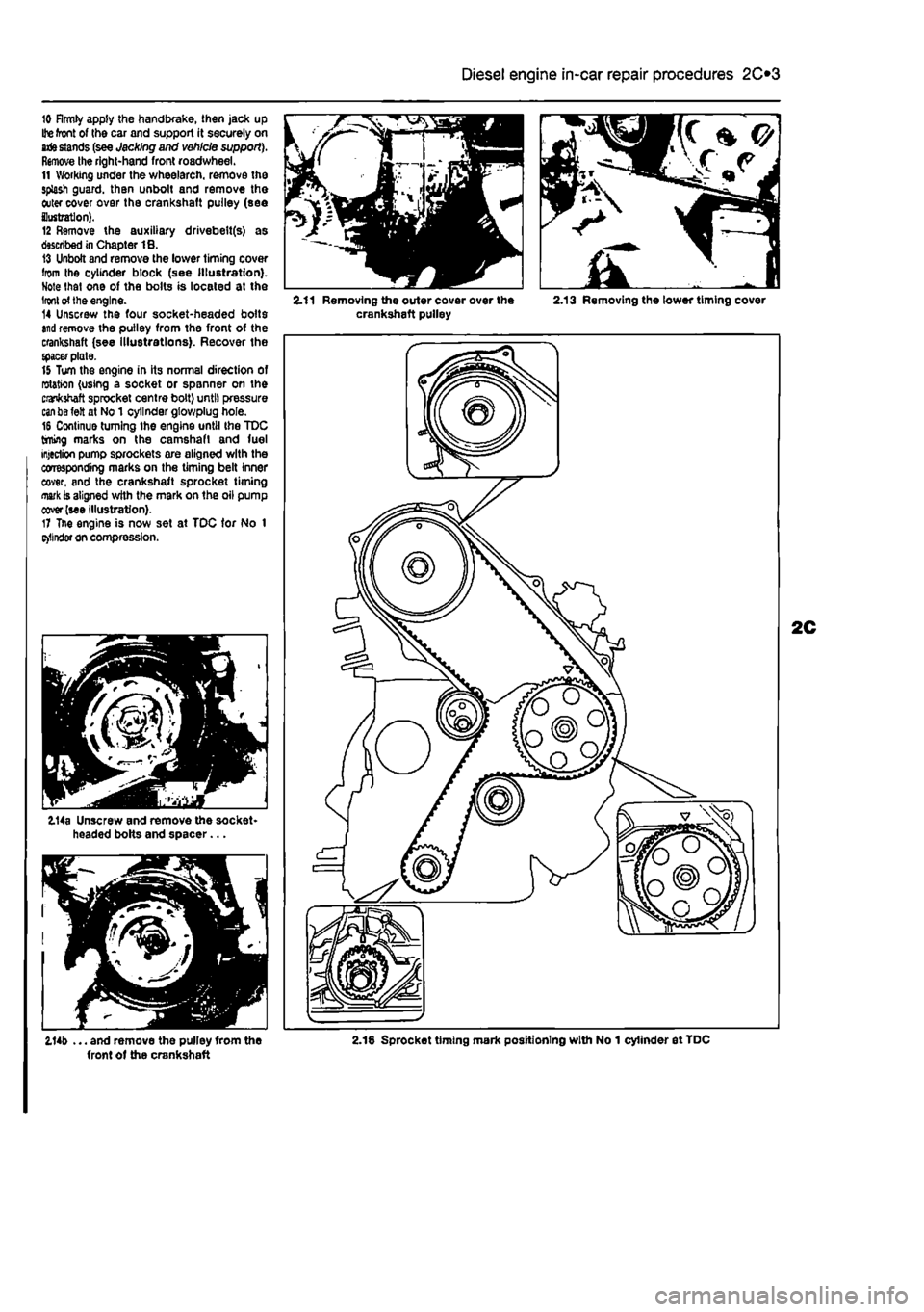
(see Jacking and vehicle support). Remove the right-hand front roadwheel. 11 Working under the wheelarch. remove the splash guard, than unbolt and remove the outer cover over the crankshaft pulley (see ilustratlon). 12 Remove the auxiliary drivebelt(s) as described in Chapter 18. 13 Unbolt and remove the lower timing cover from the cylinder block (see Illustration). Note that one of the bolts is located at the
Iron!
of the engine. 14 Unscrew the four socket-headed bolts
and
remove the pulley from the front of the crankshaft (see illustrations). Recover the {pacer plate. 15 Turn the engine in its normal direction of rotation (using a socket or spanner on the crankshaft sprocket centre bolt) until pressure
can be
felt at No 1 cylinder gtowplug hole. 16 Continue turning the engine until the TDC timing marks on the camshaft and fuel injection pump sprockets are aligned with the corresponding marks on the timing belt inner cover, and the crankshaft sprocket timing
mark
is aligned with the mark on the oil pump cover (see illustration). 17 Tne engine is now set at TDC tor No 1 e>llnder on compression.
114a Unscrew and remove the socket-headed bolts and spacer...
2.11 Removing the outer cover over the 2.13 Removing the lower timing cover crankshaft pulley
2.14b ... and remove the pulley from the 2.18 Sprocket timing mark positioning with No 1 cylinder et TDC front of the crankshaft