cran bolts FIAT PUNTO 1995 176 / 1.G Owner's Manual
[x] Cancel search | Manufacturer: FIAT, Model Year: 1995, Model line: PUNTO, Model: FIAT PUNTO 1995 176 / 1.GPages: 225, PDF Size: 18.54 MB
Page 82 of 225
2C*2 Diesel engine in-car repair procedures
9.31c Removing the inner timing cover
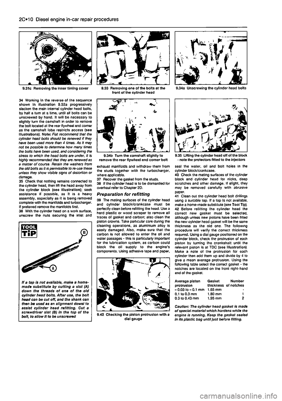
34 Working in ihe reverse of Ihe sequence shown In illustration 9.52a progressively slacken the main Internal cylinder head bolts, by halt a turn at a time, until all bolts can be unscrewed by hand. It will be necessary to slightly turn the camshaft in order to remove the bolt located at the rear llywheel end comer as the camshaft lobe restricts access (see illustrations). Note: Fiat recommend that the cylinder head boils should be renewed if they have been used more than 4 times. As It may not be possible to determine how many times the bolts have been used. end considering the stress to which the head bolts are under, it is highly recommended that they are renewed as a matter of course. Retain ihe washers from the old bolts as it is permissible to re-use these unless they show visible signs of distortion or damage. 35 Check that nothing remains connected to the cylinder head, then lift the head away from the cylinder block (see Illustration); seek assistance if possible, as It is a heavy assembly, especially as it is being removed complete with the manifolds and turbochargar. If preferred remove the manifolds first. 36 With the cylinder head on a work surface, unscrew the nuts securing the inlet and
3.33 Removing one of the bolts at the front of the cylinder head 9.34a Unscrewing the cylinder head bolts
ff a tapis not available, make a home-made substitute by cutting a slot (A) down the threads of one of the old cylinder head bolts. After use, the bolt head can be cut off, and the shank can then be used as an alignment dowel to assist cylinder head refitting. Cut a screwdriver slot (B) In the top of the bolt, to allow it to be unscrewed
9.34b Turn the camshaft slightly to remove the rear flywheel end comer boit exhaust manifolds and withdraw them from the studs together with the turbocharger. where applicable. 37 Recover the gasket from the studs. 38 If the cylinder head is to be dismantled for overhaul refer to Chapter 2D. Preparation for refitting 39 The mating surfaces of the cylinder head and cylinder block/crankcase must be perfectly clean before refitting the head. Use a hard plastic or wood scraper to remove all traces of gasket and carbon; also dean the piston crowns, Take particular care during the cleaning operations, as aluminium alloy is easily damaged. Also, make sure that the carbon is not allowed to enter the oil and water passages - this is particularly important for the lubrication system, as carbon could block the oil supply to the engine's components. Using adhesive tape and paper.
9.42 Checking the piston protrusion with a dial gauge
9.35 Lifting the cylinder head off of the block - note the protectors fitted to the injectors seal the water, oil and bolt holes In the cylinder block/crankcase. 40 Check the mating surfaces of the cylinder block and cylinder head for nicks, deep scratches and other damage. If slight, (hey may be removed carefully with abrasive paper, 41 Clean out the cylinder head bolt drillings using a suitable tap, If a tap Is not available, make a home-made substitute (see Tool Tip). 42 Before refitting the cylinder head th* correct new gasket must be selected, although unless new pistons have been fitted the new cylinder head gasket will be the same thickness as the old one. The following procedure will verify the correct thickness required. Using a dial gauge positioned on the cylinder block, check the protrusion of each piston by turning the crankshalt until the relevant piston Is at TDC (see Illustration). Make a note of the protrusion for oach cylinder then add them up and divide by 4 to give a mean average protrusion, Using the following table select the correct gasket - Ihe notcnes are located on the Iront right-hand end of (he gasket.
Average piston Gasket Number protrusion thickness of notches -0.03 to -0.1 mm 1.65 mm
0.1
to 0.3 mm 1.80 mm 1 0.3 to 0.43 mm 1.95 mm 2
Caution: The cylinder head gasket Is made of special material which hardens while the engine is running. Keep the gasket sealed in Its plastic bag until Just before fitting.
Page 83 of 225
Diesel engine in-car repair procedures 2C*11
r
<3^
9.46a The locating dowel in the cylinder block 43 It is possible for the ptston crowns to stnke and damage the valve heads, if the camshaft is rotated v/ith the timing belt removed and the crankshaft set to TDC. For this reason, the crankshaft must be set to a position other than TDC on No t cylinder before the cylinder head is refitted. Use a socket on the crankshaft pulley centre bolt to turn the crankshaft in its normal direction of rotation, until all four pistons are positioned Halfway down their bores, v/ith No 1 piston on lis upstroke - approximately 90° before TDC.
Refitting 44 If the manifolds are being refitted before refitting the cylinder head proceed as follows, otherwise fit the manifolds later when the head is refitted. Ensure thai the inlet and exhaust manifold mating surfaces are completely clean, then locale the new gasket on the studs. 45 Locate the inlet and exhaust manifolds together with the turbocharger, where applicable, on the studs. Refit the nuts and washers and tighten to the specified torque.
sequence
f^/f
9.52b Tighten the cylinder head bolts to the Stage 1 and Stage 2 settings using a torque wrench
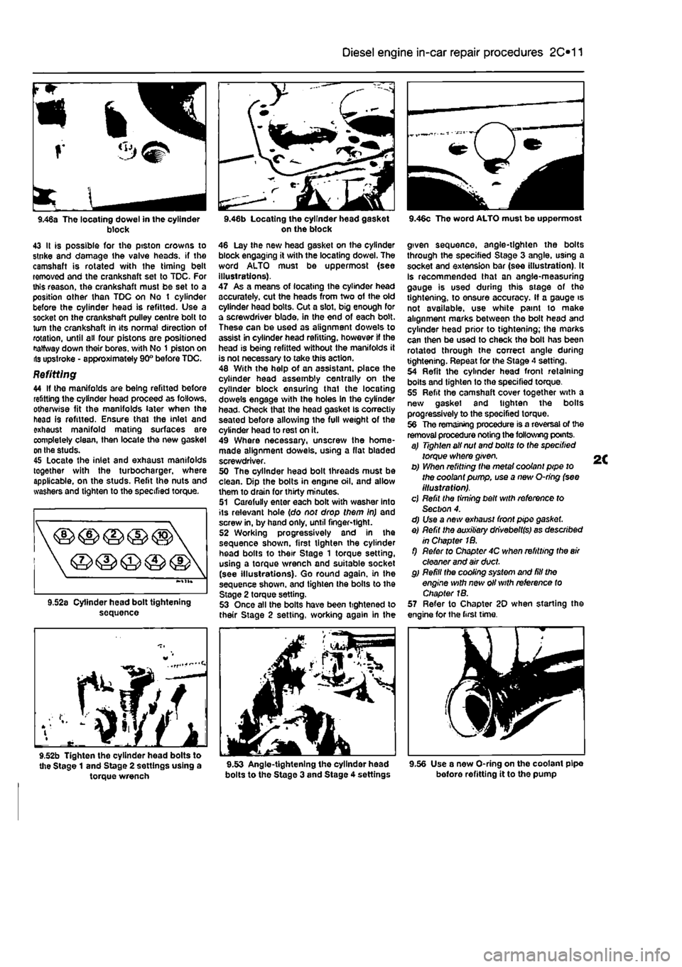
on the block 46 Lay the new head gasket on the cylinder block engaging it with the locating dowel. The word ALTO must be uppermost (see illustrations). 47 As a means of locating Ihe cylinder head accurately, cut the heads from two of the old cylinder head bolts. Cut a slot, big enough for a screwdriver blade, in the end of each bolt. These can be used as alignment dowels to assist in cylinder head refitting, however If the head is being refitted without the manifolds it is not necessary to take this action. 48 With the help of an assistant, place the cylinder head assembly centrally on the cylinder block ensuring thai the locating dowels engage with Ihe holes in the cylinder head. Check that the head gasket Is correctly seatod before allowing the full weight of the cylinder head to rest on it. 49 Where necessary, unscrew the home-made alignment dowels, using a flat bladed screwdriver. 50 The oyllnder head bolt threads must be clean. Dip the bolts in engine oil. and allow them to drain for thirty minutes. 51 Carefully enter each bolt with washer into its relevant hole (do not drop them in) and screw in, by hand only, until finger-tight. 52 Working progressively and In the sequence shown, first tighten the cylinder head bolts to their Stage 1 torque setting, using a torque wrench and suitable socket (see illustrations). Go round again, in the sequence shown, and tighten the bolls to the Stage 2 torque setting. 53 Once all the bolts have been tightened to their Stage 2 setting, working again in the
bolts to the Stage 3 and Stage 4 settings
9.46c The word ALTO must be uppermost
given sequence, angle-tighten the bolts through the specified Stage 3 angle, using a socket and extension bar (see illustration). It Is recommended that an angle-measuring gauge is used during this stage of the tightening, to ensure accuracy. If a gauge is not available, use white paint to make alignment marks between the bolt head and cylinder head prior to tightening; the marks can then be used to check tho bolt has been rotated through the correct angle during tightening. Repeat for the Stage 4 setting. 54 Refit the cylinder head front retaining bolts and tighten lo the specified torque. 55 Refit the camshaft cover together with a new gasket and tighten the bolts progressively to the specified torque. 56 The remaining procedure is a reversal of the removal procedure noting the following points. a) Tighten all nut and bolts to the specified torque where given. b) When refitting the metal coolant pipe to the coolant pump, use a new O-ring (see illustration). cj Refit the timing belt with reference to Section 4. d) Use a new exhaust front pipe gasket. e) Refit the auxiliary dhvebeltfs) as described in Chapter 1B. f) Refer to Chapter 4C when refitting the
air
cleaner and air duct. g) Refill the cooling system and fill the engine with new oil with reference to Chapter 1B. 57 Refer to Chapter 20 when starting the engine for the first time.
9.56 Use a new O-ring on the coolant pipe before refitting it to the pump
Page 84 of 225
2C*2 Diesel engine in-car repair procedures
10.2 Locking the flywheel using a homo* made tool
10 Flywheel - £ removal, inspection § and refitting ^
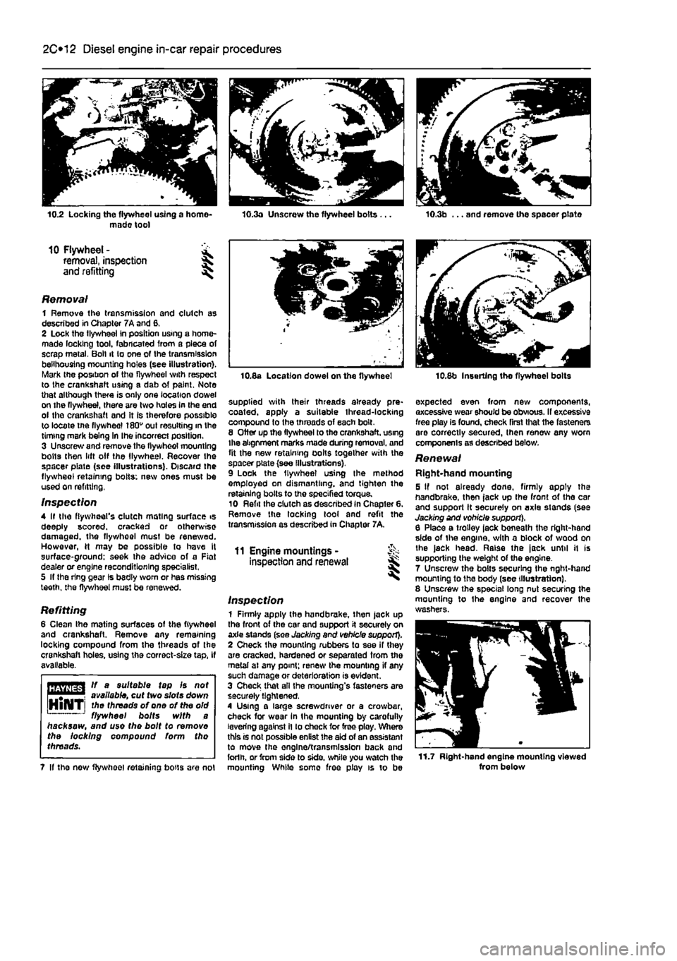
Removal 1 Remove the transmission and clutch as described in Chapter 7A and 6, 2 Lock the tlywheei in position using a home-made locking tool, fabricated from a piece of scrap metal. Boll it to one of the transmission belihousing mounting holes (see illustration). Mark the position of the flywheel with respect to the crankshaft using a dab of paint. Note that although there is only one location dowel on the flywheel, there are two holes In the end ol the crankshaft and it Is therefore possible to locate tne flywheel 180v out resulting in the timing mark being In Ihe incorrect position. 3 Unscrew and remove the flywheol mounting bolts then lift olf the llywheel. Recover the spacer piate (see illustrations). Discard the flywheol retaining bolts: new ones must be used on refitting,
Inspection 4 If the flywheel's clutch mating surface >s deeply scored, cracked or otherwise damaged, the flywhoel must be renewed. However, H may be possible to have It surface-ground: seek the advice of a Fiat dealer or engine reconditioning specialist, 5 If the ring gear Is bsdly worn or has missing teeth, the flywheel must be renewed.
Refitting 6 Clean the mating surfaces of the flywheel and crankshaft. Remove any remaining locking compound from the threads of the crankshaft holes, using the correct-size tap, if available.
HBTiffSrl If a suitable tap Is not
Wijlilfil
available, cut two slots down HlNTi threads of one of the old 1 J flywheel bolts with a hacksaw, and use the bolt to removo the locking compound form tho threads.
7 If the now flywheel retaining bous are not
10.8a Location dowel on the flywheel
supplied with their threads already pre* coated, apply a suitable thread-locking compound to the threads of each bolt. 8 Otter up the flywheel to the crankshaft, using the abgnment marks made during removal, and fit the new retaining oolts together with the spacer plate (see Illustrations). 9 Lock the flywheel using Ihe method employed on dismantling, and tighten the retaining bolts to the specified torque. 10 Refit the clutch as described in Chapter 6. Remove the locking tool and refit the transmission as described in Chapter 7A,
11 Engine mountings -inspection and renewal
Inspection 1 Firmly apply the handbrake, then jack up the front of the car and support it securely on axle stands (see Jacking and vehicle support). 2 Check the mounting rubbers to see if they are cracked, hardened or separated from the metal ai any point; renew Ihe mounting if any such damage or deterioration is evident. 3 Check that all the mounting's fasteners are securely tightened, 4 Using a large screwdriver or a crowbar, check for wear In the mounting by carefully levering against il to check for free ploy. Where this is not possible enlist the aid of an assistant to move the onglno/transmission back and forlh. or from side lo side, while you watch the mounting While some free play is to be
10.8b Inserting tho flywheel bolts
expected even from new components, axcessive wear should be obvious. II excessive free play Is found, check first that the fasteners are correctly secured, then renew any worn components as described below.
Renewal Right-hand mounting 5 If not already done, firmly apply the handbrake, then jack up the front ot tho car and support it securely on axle stands (see Jacking and vohicle support), 6 Place a trolley lack beneath the right-hand side of the engine, with a block of wood on Ihe jack head. Raise the jack until it is supporting the weight of the engine. 7 Unscrew the bolts securing the nght-hand mounting to the body (see illustration). 8 Unscrew the special long nut securing the mounting to Ihe engine and recover the washers.
11.7 Right-hand engine mounting viewed from below
Page 85 of 225
11.15 Left-hand engine mounting viewed from below 9 lower the engine sufficiently to remove the mounting from the engine bracket. 10 Locate the new mounting in the engine bracket, refit the nut and washers and tighten securely. 11 Raise the engine and refit and tighten the mounting-to-body bolts. 12 Remove the trolley jack and lower the vehicle to the ground. Left-hand mounting 13 If not already done, firmly apply the handbrake, then jack up the front of the car and support It securely on axle stands (see
Jacking
and vehicle support). 14 Place a trolley jack beneath the trans-mission. with a block of wood on the jack head. Raise the jack until it is supporting the weight of the engine/transmission. 15 Unscrew the bolts securing the left-hand mounting to the body (see Illustration). 16 Unscrew the nut securing the mounting to the transmission bracket and recover the washers. 17 Lower the transmission sufficiently to remove the mounting from the transmission bracket. 18 Locate the new mounting in the transmission bracket, refit the nut and washers and tighten securely. 19 Raise the engine and refil and tighten the mounting-to-body bolts. 20 Remove the trolley jack and lower the vehicle to the ground. Rear mounting 21 If not already done, firmly apply the handbrake, then jack up the front of the car and support it securely on axle stands (see
Jacking
and vehicle support). 22 Working beneath the vehicle, unscrew the bolts securing the rear engine mounting to the underbody (see illustration). 23 Temporarily support the weight of the engine/transmission using a trolley jack. 24 Unbolt the rear mounting assembly from the transmission and withdraw from under the vehicle. 25 Unscrew the bolt and separate the bracket from the mounting. 28 Fitting the new mounting is a reversal of tha removal procedure.
Diesel engine in-car repair procedures 2C*11
11.22 Rear engine mounting viewed from below
12 Sump -removal and refitting
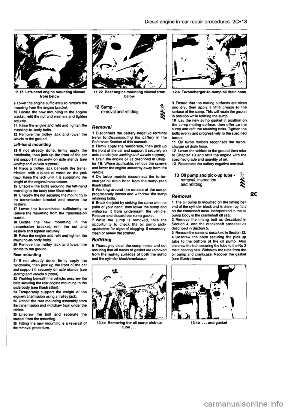
Removal 1 Disconnect the battery negativo terminal (refer to Disconnecting the battery in the Reference Section of this manual). 2 Firmly apply the handbrake, then jack up the front of the car and support it securely on axie stands (see Jacking and vehicle support). 3 Drain the engine oil as described in Chap-ter 1B. Where applicable, remove the screws and lower the engine undertray away from the vehicle. 4 On turbo models disconnect the turbo-charger oil drain hose from the sump (see illustration). 5 Working around the outside of the sump, progressively loosen and withdraw the sump retaining bolts. 6 Break the joint by striking the sump with the palm of your hand, then lower the sump and withdraw it from underneath the vehicle. Recover and discard the sump gasket. 7 While the sump Is removed, take the opportunity to check the oil pump pick-up/strainer for signs of clogging. If necessary, clean or renew the strainer.
Refitting 8 Thoroughly clean the sump inside and out ensuring that all traces of gasket are removed from the mating surfaces of both the sump and the cylinder block/crankcase.
12.4 Turbocharger-to-sump oil drain hose
9 Ensure that the mating surfaces are clean and dry, then apply a little grease to the surface of the sump. This will retain the gasket in position while refitting the sump. 10 Lay the new sump gasket In position on the sump mating surface, then offer up the sump and refit the retaining bolts. Tighten the bolts evenly and progressively lo the specified torque. 11 On turbo models reconnect the turbo-charger oil drain hose. 12 Lower the vehicle to the ground then refer to Chapter 1B and refill the engine with the specified grade and quantity of oil. 13 Reconnect the battery negative terminal.
13 Oil pump and pick-up tube -removal, inspection and refitting
Removal 1 The oil pump Is mounted on the timing belt end of the cylinder block and is driven by flats on the crankshaft nose. Incorporated In the oil pump body is the crankshaft oil seal. 2 Remove the timing belt as described in Section 4, and the crankshaft sprocket as described in Section 5. 3 Remove the sump as described in Section 12. 4 Unscrew the bolts securing Ihe pick-up tube to the bottom of the oil pump. Also unscrew the bolt securing the tube to the No 2 main bearing cap. Withdraw the tube from the oil pump and crankcase. Recover the gasket (see illustrations).
13.4a Removing the oil pump pick-up tube... 13.4b ... and gasket
Page 87 of 225
Diesel engine in-car repair procedures 2C*11
X
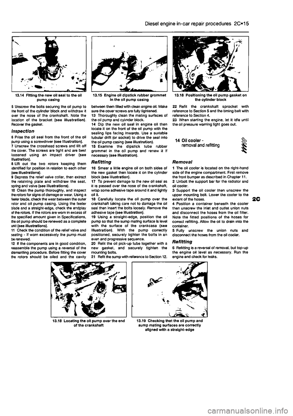
a 13.14 Fitting the new oil seal to the oil pump casing
S Unscrew the bolts securing the oil pump to Ihe front of the cylinder block and withdraw it over the nose of the crankshaft. Note the location of the bracket (see Illustration). Recover the gasket.
Inspection 8 Prise the oil seal from the front of the oil pump using a screwdriver (see Illustration). 7 Unscrew the crosshead screws and lift off the cover. The screws are tight and are best loosened using an impact driver (see illustration). S Lift out the two rotors keeping them identified for position in relation to each other (see illustrations). 9 Depress the relief valve collar, then extract the retaining plate and withdraw the seat, spring and valve (see illustrations). 10 Clean the pump thoroughly, and Inspect the rotors for signs of damage or wear. Using a feeler blade, check the wear between the outer rotor and oil pump casing. Using the feeler blade and a straight-edge, check the endptay of Ihe rotors. If the rotors are worn in excess of the specified amount given in Specifications, the oil pump should be renewed as a complete unit (see Illustrations). 11 Check the condition of the relief valve and seating - If worn excessively the pump must be renewed. 12 If the components are In good condition, reassemble the pump using a reversal of the dismantling procedure. Before fitting the cover the rotors should be oiled and the cavity
13.15 Engine oil dipstick rubber grommet in the oil pump casing between them filled with clean engine oil. Make sure the cover screws are fully tightened. 13 Thoroughly clean the mating surfaces of the oil pump and cylinder block. 14 Dip the new oil seal in engine oil then locate it on the front of the oil pump with the sealing lips facing Inwards. Use a suitable tubular drift (or socket) to drive the seal into the oil pump casing (see illustration). 16 Examine the dipstick tube rubber grommet in the oil pump and renew il If necessary (see illustration).
Refitting 16 Smear a little engine oil on both sides of the new gasket then locate it on the cylinder block (see illustration), 17 To prevent damage to the new oil seal as it is passed over the nose of the crankshaft, wrap some adhesive tape around it and lightly oil it. 18 Carefully locate the oil pump over the crankshaft taking care not to damage the oil seal then Insert the bolts loosely. Remove the adhesive tape (see Illustration). 19 Using a straight-edge, position the oil pump so that the sump mating surface Is level with the surface of the crankcase (see illustration). With the pump correctly positioned, securely tighten the bolts in an even and progressive sequence. 20 Refit the oil pick-up tube together with a new gasket, and securely tighten the mounting bolts. 21 Refit the sump with reference to Section 12.
13.16 Positioning the oil pump gasket on the cylinder block 22 Refit the crankshaft sprocket with reference to Section 5 and the timing belt with reference to Section 4. 23 When starling the engine, let it Idle until the oil pressure warning light goes out.
14 Oil cooler -removal and refitting I I
Removal 1 The oil cooler is located on the right-hand side of the engine compartment. First remove the front bumper as described In Chapter 11. 2 Unbolt the support bar for the radiator and oil cooler. 3 Support the oil cooler then unscrew the upper mounting boll. Lower the cooler to the extent of the hoses. 4 Position a container beneath the cooler then unscrew the Inlet and outlet union nuts and disconnect the hoses from the oil filter. Note the fitted positions of the hoses for correct refitting. Allow the oil to drain into the container. 5 Fully unscrew the union nuts and disconnect the hoses from the oil cooler.
Refitting 6 Refitting is a reversal of removal, but top-up the engine oil level as necessary. Run the engine and check for leaks.
13.18 Locating the oil pump over the end of the crankshaft 13.19 Checking that the oil pump and sump mating surfaces are correctly aligned with a straight-edge
Page 98 of 225
2D*10 Engine removal and overhaul procedures
05 Remove the brush holder assembly from the automatic transmission as described in Chapter 7B, Section 4. The brushes bear on the slip rings at the rear of the electro-magnetic clutch housing and they may be damaged when the transmission is removed. 86 Unscrew and remove the transmission-to-engine bolts then carefully draw the transmission away from the engine, resting It securely on wooden blocks. Collect the locating dowels If they are loose enough to be extracted, 87 If the oil pump driveshaft remains engaged with the crankshaft, remove it and reert Into the transmission to protect It from damage.
Connection 86 If the engine and transmission have not been separated, go to paragraph 104. Manual transmission models 89 Smear a little high-melting-point grease
on
the splines of the transmission input shaft. Do not use an excessive amount as there Is the risk of contaminating the clutch friction plate. 90 Carefully offer up the transmission to the engine cylinder block, guiding the input shaft through the clutch friction plate. 91 Refit the transmission-to-engine bolts and
the
single nut. hand^jghtenlng 1hem to secure the transmission in position. Note: Do not hghten them to force the engine and transmission together. Ensure that the beilhousing and cylinder block mating faces will butt together evenly without obstruction, before finally tightening the bolts and nut securely. Automatic transmission models 92 Check that the oil pump driveshaft is correctly engaged with the oil pump in the transmission. 93 Carefully offer up the transmission to Ihe rear of the engine and insert the oil pump driveshaft In the centre of the electro-magnetic clutch housing. Locate the transmission on the locating dowels then Insert the bolts and tighten them securely. 94 Refit the brush holder assembly to the automatic transmission with reference to Chapter 7B, Section 4. Petrol engines 96 Refit the transmission lower cover and tighten the bolts. 96 Locate the support bracket on the lower cover, then insert the bolts hand-tight. Also Insert the bolts securing the bracket lo the rear of Ihe cylinder block. With all the bolts Inserted, tighten them securely. 97 Refit the earth leads and tighten the bolts. Diesel engines 98 Refit the rpm sensor and tighten the bolts. 99 Insert the Intermediate shaft through the bracket then locate the dust boot on it and insert the Inner end in the transmission.
100 Refit and tighten the bolts securing the Intermediate shaft to the bracket on the rear of the cylinder block. 101 Refit the transmission lower cover and tighten the bolts. Ail models 102 Refit the starter motor (see Chapter 5A). 103 Refit the wiring harness to the components on the engine/transmission assembly making sure it is routed correctly.
Refitting 104 Locate the engine/transmission assembly beneath the engine compartment and attach the hoist to the lifting eyes. 105 Carefully lift the assembly up into the engine compartment taking care not to damage the surrounding components. 106 Reconnect the left-hand engine/trans-mission mounting to the body and tighten the bolts. 107 Reconnect Ihe right-hand engine mounting to the body and tighten the bolts. 108 Working beneath the vehicle, refit the rear engine mounting and tighten the bolts. 109 Disconnect the hoist from the engine and transmission lifting eyes and remove the hoist from under the vehicle. 110 The remainder of the refitting procedure is the direct reverse of the removal procedure, noting the following points:
a) Ensure that alf sections of the wiring harness follow their original routing; use new cable-ties to secure the harness In position, keeping it away from sources
of
heat and abrasion. b) On vehicles with manual transmission check and if necessary adjust the gearchenge cable and rod with reference to Chapter 7A. c) On vehicles with automatic transmission use new ro//p/ns fo secure the driveshafts to the transmission output stubs. Also check and if necessary adjust the kickdown end selector cables with reference to Chapter 78. d) Ensure that afi hoses are correctly routed and are secured with the correct hose clips, where applicable. If the hose clips cannot be used again; proprietary worm drive clips should be fitted
In
their place. e) Refill the cooling system as described in Chapter 1A or 18. f) Refill the engine with appropriate grades and quantities of oil (Chapter
1A
or 1B). g) Refit and adjust the auxiliary drivebelt(s) wfth reference fo Chapter 1A or 1B. h) Check and If necessary adjust the accelerator cable with reference to Chapter
AA,
48 or
AC.
i) When the engine is started for the first time, check for
air,
coolant, lubricant and fuel leaks from manifolds, hoses etc. If
the
engine has been overhauled, read
the
notes In Section 13 before attempting to starlit.
5 Engine overhaul • dismantling sequence
1 It is much easier to dismantle and work on the engine if it is mounted on a portable engine stand. These stands can often be hired from a tool hire shop. Before the engine is mounted on a stand, the flywheel should be removed, so that the stand bolts can be tightened Into the end of the cylinder block/crankcase. 2 If a stand Is not available, it Is possible to dismantle the engine with it blocked up on a sturdy workbench, or on the floor, Be very careful not to tip or drop the engine when working without a stand. 3 If you intend to obtain a reconditioned engine, all anclllarles must be removed first, to be transferred to the replacement engine (just as they will If you are doing a complete engine overhaul yourself). These components Include the following:
Petroi engines a) Power steering pump if removed with the engine (Chapter
10).
b) Alternator fmcluding mounting brackets) and starter motor (Chapter
SA).
c) The Ignition system and HT components including ail sensors, HT leads and
spark
plugs (Chapters 1A and
SB).
d) The fuel injection system components (Chapters A A and
AB).
e) All electrical switches, actuators and sensors, and the engine wiring harness (Chapters 4A, AB, SB). f) Inlet and exhaust manifolds (Chapters 4A, AB end
AD).
g) Engine oil dipstick and tube. h) Engine mountings (Chapter
2A).
i) Flywheef/driveptate (Chapter
2A).
j) Clutch components (Chapter
6)
- manual transmission. k) Electro-magnetic clutch components (Chapter 7B) - automatic transmission. I) Cooling system components (Chapter
3).
Diesei engines a) Power steering pump //removed with the engine (Chapter
10).
b) Alternator (Including mounting brackets) and starter motor (Chapter 5A). c) The glow plugfpre-heatlng system components (Chapter
SC).
d) Ait fuel system components, including the fuel injection pump, all sensors and actuators (Chapter
AC).
e) The vacuum pump. f) Ail electrical switches, actuators and sensors, and the engine wiring harness (Chapter 4C and 5C). g) Inlet and exhaust manifolds and, where applicable, the turbocharger (Chapter
AC
and 4D). h) The engine oil level dipstick and its tube. i) Engine mountings (Chapter
2C).
Page 99 of 225
2D*10 Engine removal and overhaul procedures
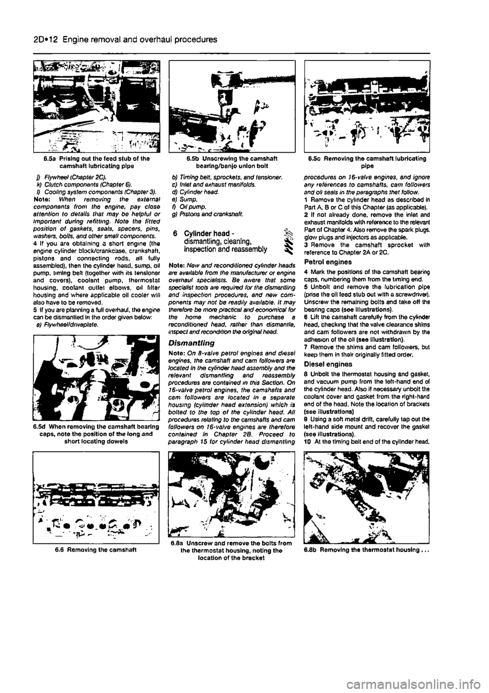
6.5s Prising out the feed stub of the camshaft lubricating pipe J) Flywheel (Chapter 2C). k) Clutch components (Chapter
6).
I) Cooling system components (Chapter
3).
Note: When removing trie external components from the engine, pay close attention to details that may be helpful or important during refitting. Note the fitted position of gaskets, seals, spacers, pins, washers, bolts, and other small components. 4 If you are obtaining a short engine (the engine cylinder block/crankcase, crankshaft, pistons and connecting rods, all fully assembled), then the cylinder head, sump, oil pump, timing belt (together with its tensloner and covers), coolant pump, thermostat housing, coolant outlet elbows, oil filter housing and where applicable oil cooler will also have to be removed. 5 If you are planning a full overhaul, the engine can be dismantled in the order given below: $) Ftywhaoi/drivoplate.
6.5d When removing the camshaft bearing caps, note the position of the (ong and short locating dowels
bearing/banjo union bolt b) Timing belt, sprockets, and tensioner. c) Inlet and exhaust manifolds. d) Cylinder head. e) Sump. f) Oil pump. g) Pistons and crankshaft.
6 Cylinder head - % dismantling, cleaning, inspection and reassembly ^
Note: Now and reconditioned cylinder heads are available from the manufacturer or engine overhaul specialists. Be aware that some specialist tools are required for the dismantling and inspection procedures, and new com-ponents may not be readily available. It may therefore be mors practical and economical for the home mechanic to purchase a reconditioned head, rather than dismantle, inspect and recondition the original head.
Dismantling Note: On 8-valve petrol engines and diesel engines, the camshaft and cam followers are /oca fed In the cylinder head assembly and the relevant dismantling and reassembly procedures are contained in this Section. On 1$-valve petrol engines, the camshafts and cam followers are /oca fed In a separate housing (cylinder head extension) which is bo/fed fo the top of the cylinder head. All procedures relating to the camshafts and cam followers on 16-valve engines are therefore contained in Chapter 2B. Proceed fo paragraph 15 for cylinder head dismantling
6.8a Unscrew and remove the bolts from the thermostat housing, noting the location of the bracket
6.5c Removing the camshaft lubricating pipe procedures on /6-vafve engines, and ignore any references to camshafts, cam followers and oil seals in the paragraphs that follow. 1 Remove the cylinder head as described in Part A. B or C of this Chapter (as applicable). 2 If not already done, remove the inlet and exhaust manifolds with reference to the relevant Part of Chapter 4. Also remove the spark plugs, glow plugs and injectors as applicable. 3 Remove the camshaft sprocket with reference to Chapter 2A or 2C. Petrol engines 4 Mark the positions of the camshaft bearing caps, numbering them from the timing end. 5 Unbolt and remove the lubrication pipe (prise the oil feed stub out with a screwdriver). Unscrew the remaining bolts and take off the bearing caps (see illustrations). 6 Lift the camshaft carefully from the cylinder head, checking lhat the valve clearance shims and cam followers are not withdrawn by the adhesion of the oil (see Illustration). 7 Remove the shims and cam followers, but keep them In their originally fitted order. Diesel engines 8 Unbolt the thermostat housing and gasket, and vacuum pump from the left-hand end of the cylinder head. Also if necessary unbolt the coolant cover and gasket from the right-hand end of the head. Note the location of brackets (see illustrations) 9 Using a soft metal drift, carefully lap out the left-hand side mount and recover the gasket (soe illustrations). 10 At tho timing bait end of the cylinder head.
6.8b Removing the thermostat housing ... 6.6 Removing the camshaft
Page 104 of 225
2D*10 Engine removal and overhaul procedures
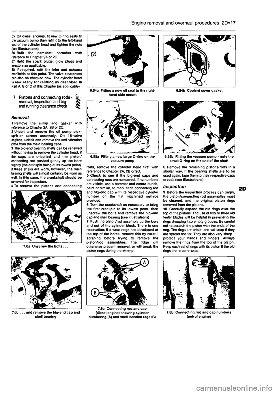
65 On diesel engines. (It new O-ring seals to the vacuum pump then refit it to the left-hand end of the cylinder head and tighten the nuts (see illustrations). 96 Refit the camshaft sprocket with reference to Chapter 2A or 2C. 57 Refit the spark plugs, glow plugs and nfectors as applicable. 58 If required, refit the inlet and exhaust manifolds at this point. The valve clearances can also be checked now. The cylinder head is now ready for refitting as described In Part A, B or C of this Chapter (as applicable).
7 Pistons and connecting rods -removal, Inspection, and big- ^ end running clearance check ^
7.6a Unscrew the bolts.
8.54a Fitting a new oil seal to the right-hand side mount 6.54b Coolant cover gasket
Removal 1 Remove the sump and gasket with reference to Chapter 2A, 2B or 2C. 2 Unbolt and remove the oil pump pick-up/lilter screen assembly. On 16-valve engines, unbolt ond remove the anti-vibration ptate from the main bearing caps. 3 The big-end bearing shells can be renewed without having to remove the cylinder head, If the caps are unbolted and the piston/ connecting rod pushed gently up the bore slightly (the crankpin being at Its lowest point). It ihe3e shells are worn, however, the main bearing shells will almost certainly be worn as well. In this case. Ihe crankshaft should be removed for inspection. 4 To remove the pistons and connecting
6.55a Fitting a now large O-ring on the vacuum pump rods, remove the cylinder head first with reference to Chapter 2A, 2B or 2C. 5 Check to see if the big-end caps and connecting rods are numbered. If no numbers are visible, use a hammer and centre-punch, paint or similar, to mark each connecting rod and big-end cap with its respective cylinder number on the flat machined surface provided. 6 Turn the crankshaft as necessary to bring the first crankpin to its lowest point, then unscrew the bolts and remove the big-end cap and shell bearing (see illustrations). 7 Push the piston/rod assembly up the bore and out of the cylinder block. There is one reservation; if a wear ndge has developed at the top of the bores, remove this by careful scraping before trying to remove the piston/rod assemblies. Tho ridge will otherwise prevent removal, or wilt broak the piston nngs during the attempt.
.55b Fitting the vacuum pump • note the small O-ring on the end of the shaft 6 Remove the remaining pistons/rods In a similar way. If the boaring shells are to be used again, tape them to their respective caps or rods (see illustrations).
Inspection 9 Before the inspection process can begin, the piston/connecting rod assemblies must be cleaned, and the original piston rings removed from the pistons. 10 Carefully expand the old rings over the top of the pistons. The use of two or three old feeler blades will be helpful In preventing the rings dropping into empty grooves. Be careful not to scratch the piston with the ends of the nng. The rings are brittle, and will snap if they are spread too tar. They are also very sharp -protect your hands and fingers. Always remove the rings from the top of the piston. Keep each set of nngs with its piston If the old rings are to be re-used.
.. and remove the big-end cap and shell bearing
7.8a Connecting rod and cap (diesel engine) showing cylindor numbering (A) and shell location tags (B) 7.8b Connecting rod and cap numbers (petrol engine)
Page 105 of 225
2D*10 Engine removal and overhaul procedures
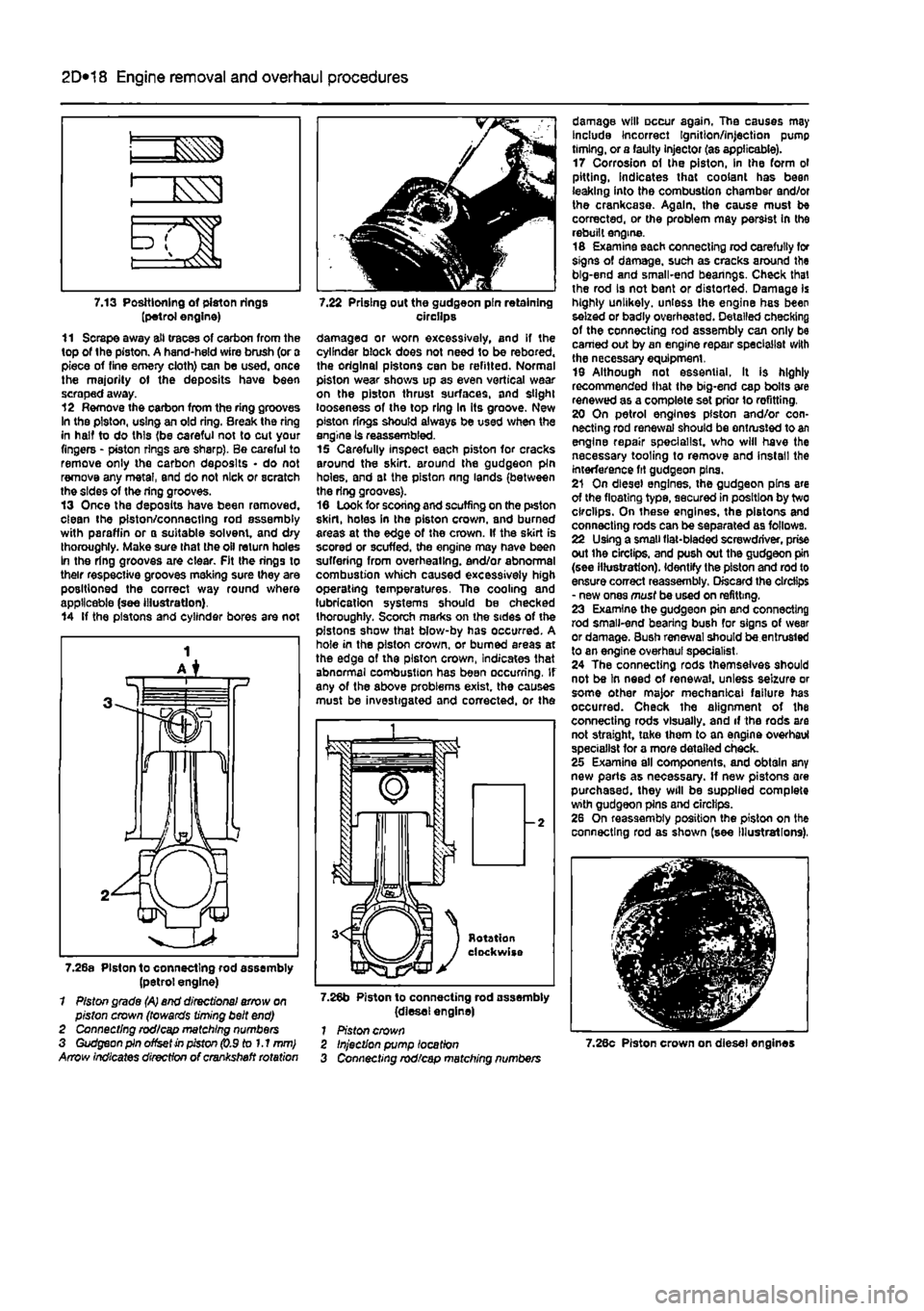
7.13 Positioning of piston rings (petrol engine) 11 Scrape away all traces of carbon from the top of the piston. A hand-held wire brush (or a piece of fine emery cloth) can be used, once the majority ot the deposits have been scraped away. 12 Remove the carbon from the ring grooves In the piston, using an old ring. Break the ring in half to do this (be careful not to cut your fingers - piston rings are sharp). Be careful to remove only the carbon deposits • do not remove any metal, end do not nick or scratch the sides of the ring grooves. 13 Once the deposits have been removed, clean the piston/connecting rod assembly with paraffin or o suitable solvent, and dry thoroughly. Make sure that the oil return holes In the ring grooves are clear. Fit the rings to their respective grooves meking sure they are positioned the correct way round where applicable (see illustration). 14 If the pistons and cylinder bores are not
7.22 Prising out the gudgeon pin retaining circilps damagea or worn excessively, and if the cylinder block does not need to be rebored. the original pistons can be refitted. Normal piston wear shows up as even vertical wear on the piston thrust surfaces, and slight looseness of the top ring In its groove. New piston rings should always be used when the engine is reassembled. 15 Carefully inspect each piston for cracks around the skirt, around the gudgeon pin holes, and at the piston nng lands (between the ring grooves). 16 Look for scoring and scuffing on the ptston skirt, holes in the piston crown, and burned areas at the edge of the crown. If the skirt is scored or scuffed, the engine may have been suffering from overheating, end/or abnormal combustion which caused excessively high operating temperatures. The cooling and lubrication systems should be checked thoroughly. Scorch marks on the sides of the pistons show that blow-by has occurred. A hole in the piston crown, or burned areas at the edge of the piston crown, Indicates that abnormal combustion has been occurring. If any of the above problems exist, the causes must be investigated and corrected, or the
7.26a Piston to connecting rod assembly (petrol engine) 1 Piston grade (A) end directional arrow on piston crown (towards timing belt end) 2 Connecting rod/cap matching numbers 3 Gudgeon pin offset in piston (0.9 to 1.1 mm) Arrow indicates direction of crankshaft rotation
7.26b Piston to connecting rod assembly (diesel engine) 1 Piston crown
damage will occur again. The causes may Include Incorrect Ignition/injection pump timing, or a faulty injector (as applicable). 17 Corrosion of the piston, in the form ol pitting, indicates that coolant has been leaking into the combustion chamber and/or the crankcase. Again, the cause must be corrected, or the problem may persist In the rebuilt engine. 16 Examine each connecting rod carefully for signs of damage, such as cracks around the big-end and small-end bearings. Check that the rod is not bent or distorted, Damage is highly unlikely, unless the engine has been seized or badly overheated. Detailed checking of the connecting rod assembly can only be earned out by an engine repair specialist with the necessary equipment. 19 Although not essential. It is highly recommended that the big-end cap bolts are renewed as a complete set prior lo refitting. 20 On petrol engines piston and/or con-necting rod renewal should be entrusted to an engine repair specialist, who will have the necessary tooling to remove and install the interference fit gudgeon pins. 21 On diesel engines, the gudgeon pins are of the floating type, secured in position by two circlips. On these engines, the pistons and connecting rods can be separated as follows. 22 Using a small fiat-bladed screwdriver, prise out ihe circlips, and push out the gudgeon pin (see illustration). Identify the piston and rod to ensure correct reassembly. Discard the circlips - new ones must be used on refitting. 23 Examine the gudgeon pin and connecting rod small-end bearing bush for signs of wear or damage. Bush renewal should be entrusted to an engine overhaul specialist. 24 The connecting rods themselves should not be In need of renewal, unless seizure or some other major mechanical failure has occurred. Check the alignment of the connecting rods visually, and if the rods are not straight, take ihem to an engine overhaul specialist for a more detailed check. 25 Examine all components, and obtain any new parts as necessary. If new pistons are purchased, they will be supplied complete with gudgeon pins and circlips. 26 On reassembly position the piston on the connecting rod as shown (see Illustrations),
Injection pump location Connecting rod/cap matching numbers 7.28c Piston crown on diesel engines
Page 106 of 225
Apply a smear of clean engine oil to the gudgeon pin. Slide it Into the piston and through the connecting rod small-end. Check that the piston pivots freely on the rod. then secure the gudgeon pin in position with two new circlips. Ensure that each circlip is correctly located In Its groove in the piston.
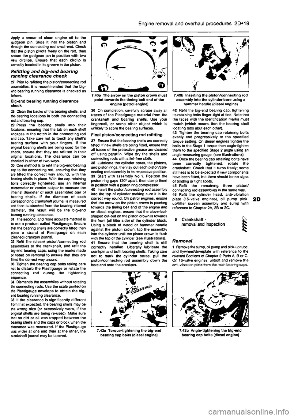
Refitting and big-end bearing running ciearance check 27 Prior to refitting the piston/connecting rod assemblies, it Is recommended that the big-end bearing running clearance is checked as follows. Big-end bearing running clearance check 28 Clean the backs of the bearing shells, and the bearing locations in both the connecting rod and bearing cap. 29 Press the bearing shells into their locations, ensuring that the tab on each shell engages in the notch In the connecting rod and cap. Take care not to touch any shell's bearing surface with your fingers. If the onginal bearing shells are being used for the check, ensure that they are refitted in their original locations. The clearance can be checked in either of two ways. 30 One method is to refit the big-end bearing cap to Ihe connecting rod, ensuring that they are litted the correct way around, with the bearing shells in place. Wilh the cap retaining bolls correctly tightened, use an internal micrometer or vernier caliper to measure the internal diameter of each assembled pair of bearing shells. If the diameter of each corresponding crankshaft journal is measured and Ihen subtracted from the bearing internal diameter, the result will be the big-end beanng running clearance. 31 The second, and more accurate method is to use a product called Plasligauge. Ensure that the bearing shells are correctly fitted then place a strand of Plastlgauge on each (cleaned) crankpin journal. 32 Refit the (clean) piston/connecting rod assemblies to the crankshaft, and refit the bg-end bearing caps, using the marks made or noted on removal to ensure that they are fitted the correct way around. 33 Tighten the beanng cap bolts taking care not to disturb the Plastlgauge or rotate the connecting rod dunng the tightening sequence. 34 Dismantle the assemblies without rotating the connecting rods. Use the scale pnnted on the Plastigauge envelope to obtain the big-end bearing running clearance. 35 If the clearance is significantly different from that expected, the bearing shells may be Ihe wrong size (or excessively worn. If the original shells are being re-used). Make sure mat no dirt or oil was trapped between Ihe bearing shells and the caps or block when the clearance was measured. If the Plastigauge was wider al one end than at the other, the crankshaft journal may be tapered.
2D*10 Engine removal and overhaul procedures
7.40a The arrow on the piston crown must point towards the timing belt end of the engine (petrol engine) 36 On completion, carefully scrape away all traces of the Plastigauge material from the crankshaft and bearing shells. Use your fingernail, or some other object which is unlikely to score the beanng surfaces.
Final piston/connecting rod refitting 37 Ensure that the bearing shells are correctly fitted. If new shells are being fitted, ensure that alt traces of the protective grease are cleaned off using paraffin. Wipe dry the shells and connecting rods with a lint-free cloth. 38 Lubricate the cylinder bores, the pistons, and piston rings, then lay out each piston/con-necting rod assembly in its respective position. 39 Start with assembly No 1. Position the piston ring gaps 120° apart, then clamp them in position with a piston nng compressor. 40 Insert Ihe piston/connecting rod assembly into the top of cylinder making sure it is Ihe correct way round. On petrol engines, ensure that the arrow on the piston crown is pointing towards the timing belt end of the engine and on diesel engines, ensure that the cloverleaf-shaped cut-out on the piston crown is towards the front (oil filter side) of the cylinder block. Using a block of wood or hammer handle against the piston crown, tap the assembly into the cylinder until the piston crown is Hush with the top of the cylinder (sea illustrations). 41 Ensure that the bearing shell is still correctly Installed. Liberally lubricate the crankpin and both bearing shells. Taking care not to mark the cylinder bores, pull the piston/connecting rod assembly down the bore and onto the crankpin.
7.40b Inserting the piston/connecting rod assembly into the cylinder bore using a hammer handle (diesel englno) 42 Refit the big-end beanng cap, tightening Its retaining bolts finger-tight at first, Note that Ihe faces with the identification marks must match (which means that the bearing shell locating tabs abut each other). 43 Tighten the bearing cap retaining bolts evenly and progressively to the specified torque setting. On diesel engines tighten the bolts to the Stage 1 torque then angle-tighten them to the specified Stage 2 angle using an angle-measuring gauge, (see illustrations) 44 Once the bearing cap retaining bolts have been correctly tightened, rotate the crankshaft. Check that il turns freely; some stiffness is to be expected if new components have been fitted, but there should be no signs of binding or tight spots. 45 Refit the remaining three piston/ connecting rod assemblies in the same way. 46 Refit the cylinder head, anti-vibration plate (16-valve engines), oil pump pick-up/filter screen assembly and sump with reference to Chapter 2A, 2B or 2C.
8 Crankshaft -removal and inspection 35
Removal 1 Remove the
sump,
oil pump and pick-up tube, and flywheel/driveplate with reference to the relevant Sections of Chapter 2 Parts A, 8 or C. On 16-valve engines, unbolt and remove the anti-vibration plate from the main bearing caps.
7.43a Torque-tightening the big-end bearing cap bolls (diesel engine) 7.43b Angle-tightening the big-end bearing cap bolts (diesel engine)