fuse FIAT PUNTO 1998 176 / 1.G Workshop Manual
[x] Cancel search | Manufacturer: FIAT, Model Year: 1998, Model line: PUNTO, Model: FIAT PUNTO 1998 176 / 1.GPages: 225, PDF Size: 18.54 MB
Page 17 of 225
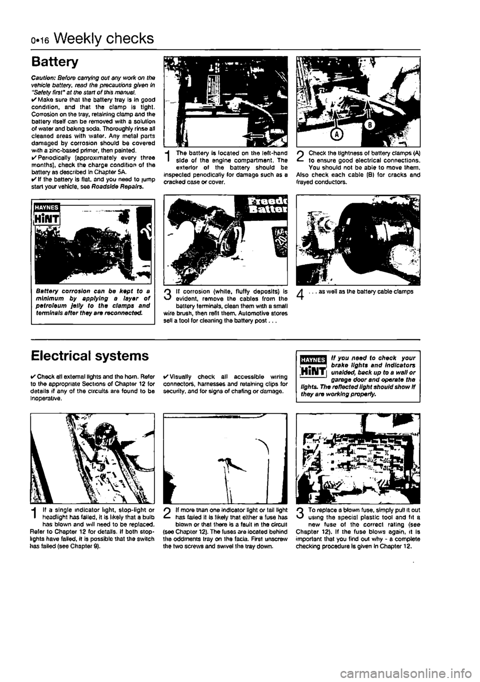
o«i6 Weekly checks
Battery
Caution: Before carrying out any work on the vehicle battery, read the precautions given In "Safety first" at the start of this manual. • Make sure thai the battery tray is in good condition, and that the clamp Is tight. Coirosion on the tray, retaining clomp and the battery itself can be removed with a solution of water and baking soda, Thoroughly rinse all cleaned areas with water. Any metal parts damaged by corrosion should be covered with a zinc-based primer, then painted. • Periodically (approximately every three months), check the charge condition of the battery as described In Chapter SA. • If the battery Is flat, and you need to jump start your vehicle, see Roadside Repalrz.
Battery corrosion can be kept to a minimum by applying o layer of petroleum Jelly to the clamps and terminals after they are reconnected
fin %
I
The battery is located on the left-hand side of the engine compartment, The exterior of the battery should be inspected penodlcaily for damage such as a cracked case or cover.
2
Check the tightness of battery clamps (A) to ensure good electrical connections. You should not be able to move them. Also check each cable (B) for cracks and frayed conductors.
3
If corrosion (while, fluffy deposits) is evident, remove the cables from the battery terminals, clean them with a small wire brush, then refit them. Automotive stores sell a tool for cleaning the battery post...
as well as the battery cable clamps
Electrical systems
• Check all external lights and the horn. Refer to the appropriate Sections of Chapter 12 for details if any of the circuits are found to be Inoperative,
• Visually chock all accessible wiring connectors, harnesses and retaining clips for security, and for signs of chafing or damage.
fffjffflg^ " y°u A**^ check your "T™*! broke lights and Indicators ,HllMT[ unaided, back up to a wall or garage door and operate the lights. The reflected light shouid show
If
they are working property.
I
I? a single indicator light, stop-light or headlight has failed, it Is likely that a bulb has blown and will need to be replaced. Refer to Chapter 12 for details. If both stop-lights have failed, it is passible that the switch has failed (see Chapter 9).
2
If more than one Indicator light or tail light has failed It is likely that either a fuse has blown or that there is a fault tn the circuit (see Chapter 12). The fuses are located behind the oddments tray on ihe facia. First unscrew the two screws and swivel Ihe tray down.
3
To replace a blown fuse, simply pull it out using the special plastic tool and fit a new fuse of tho correct rating (see Chapter 12). If the fuse blows again, it is importont that you find out why - a complete checking procedure Is given in Chapter 12.
Page 92 of 225
2D*10 Engine removal and overhaul procedures
Engine and transmission -removal, separation, connection and refitting
Note: The engine Is lowered from the engine compartment as a complete unit with the transmission; tho two are then separated for overhaul.
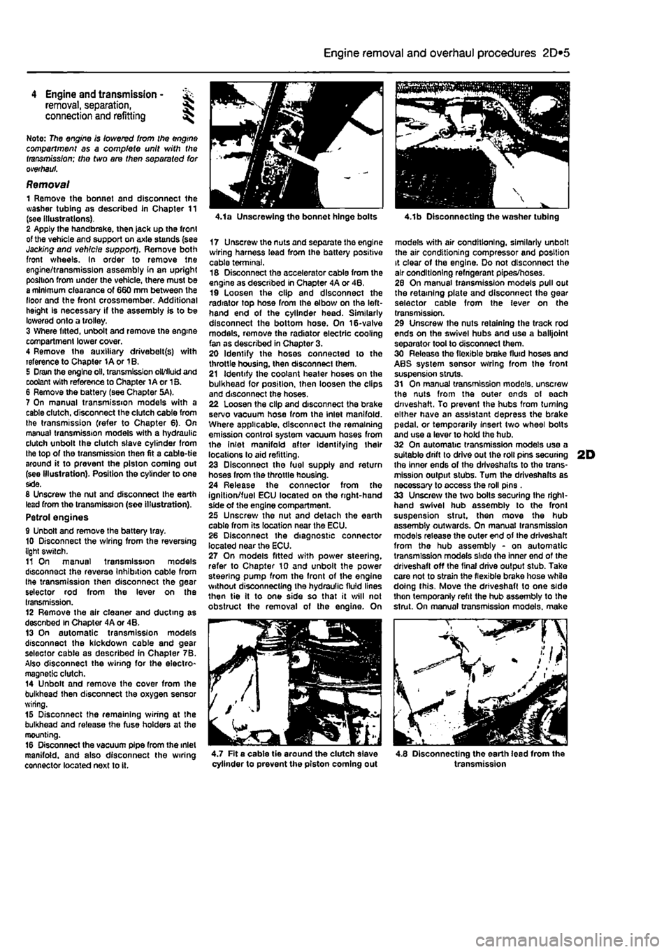
Removal 1 Remove the bonnet and disconnect the washer tubing as described in Chapter 11 (see illustrations). 2 Apply the handbrake, then jack up the front of the vehicle and support on axle stands (see Jacking and vehicle support). Remove both front wheels. In order to remove tne engine/transmission assembly in an upright position from under the vehicle, there must be a minimum clearance of 660 mm between the floor and the front crossmember. Additional height Is necessary if the assembly is to be lowered onto a trolley. 3 Where fitted, unbolt and remove the engine compartment lower cover. 4 Remove the auxiliary drivebelt(s) with reference to Chapter 1A or 1B. 5 Dram the engine oil. transmission oil/fluid and coolant with reference to Chapter 1A or 1B. 6 Remove the battery (see Chapter 5A). 7 On manual transmission models with a cable dutch, disconnect the clutch cable from the transmission (refer to Chapter 6). On manual transmission models with a hydraulic clutch unbolt the clutch slave cylinder from the top of the transmission then fit a cable-tie around it to prevent the piston coming out (see Illustration). Position the cylinder to one side. 8 Unscrew the nut and disconnect the earth lead from the transmission (see illustration). Petrol engines 9 Unbolt and remove the battery tray. 10 Disconnect the wiring from the reversing light switch. 11 On manual transmission models disconnect the reverse Inhibition cable from the transmission then disconnect the gear selector rod from the lever on the transmission. 12 Remove the air cleaner and ducting as descnbed In Chapter 4A or 4B. 13 On automatic transmission models disconnect the kickdown cable and gear selector cable as described in Chapter 7B. Also disconnect the wiring for the electro-magnetic clutch. 14 Unbolt and remove the cover from the bulkhead then disconnect the oxygen sensor wiring. 15 Disconnect the remaining wiring at the bulkhead and release the fuse holders at the mounting. 16 Disconnect the vacuum pipe from the inlet manifold, and also disconnect the wiring connector located next to it.
4.1a Unscrewing the bonnet hinge bolts
17 Unscrewthenutsandseparatetheengine wiring harness lead from the battery positive cable terminal. 18 Disconnect the accelerator cable from the engine as described in Chapter 4A or 4B, 19 Loosen the clip and disconnect the radiator top hose from the elbow on the left-hand end of the cylinder head. Similarly disconnect the bottom hose. On 16-valve models, remove the radiator electric cooling fan as described in Chapter 3. 20 Identify the hoses connected to the throttle housing, then disconnect them. 21 Identify the coolant heater hoses on the bulkhead for position, then loosen the clips and disconnect the hoses. 22 Loosen the clip and disconnect the brake servo vacuum hose from the Inlet manifold. Where applicable, disconnect the remaining emission control system vacuum hoses from the Inlet manifold after Identifying their locations to aid refitting. 23 Disconnect tho fuel supply and return hoses from the throttle housing. 24 Release the connector from the ignition/fuel ECU located on the right-hand side of the engine compartment. 25 Unscrew the nut and detach the earth cable from its location near the ECU. 26 Disconnect the diagnostic connector located near the ECU. 27 On models fitted with power steering, refer to Chapter 10 and unbolt the power steering pump from the front of the engine without disconnecting the hydraulic fluid lines then tie It to one side so that it will not obstruct the removal of the engine. On
4.1b Disconnecting the washer tubing
models with air conditioning, similarly unbolt the air conditioning compressor and position it clear of the engine. Do not disconnect the air conditioning refngerant pipes/hoses. 26 On manual transmission models pull out the retaining plate and disconnect the gear selector cable from the lever on the transmission. 29 Unscrew the nuts retaining the track rod ends on the swivel hubs and use a balljoint separator tool to disconnect them. 30 Release the flexible brake fluid hoses and ABS system sensor wrring from the front suspension struts. 31 On manual transmission models, unscrew the nuts from the outer ends of each driveshaft. To prevent the hubs from turning either have an assistant depress the brake pedal, or temporarily Insert two wheel bolts and use a lever to hold the hub. 32 On automatic transmission models use a suitable drift to drive out Ihe roll pins securing 2D the inner ends of the drlveshafts to tho trans-mission output stubs. Turn the driveshalts as necossary to access the roll pins . 33 Unscrew the two bolts securing the right-hand swivel hub assembly to the front suspension strut, then move the hub assembly outwards. On manual transmission models release the outer end of the driveshaft from the hub assembly - on automatic transmission models slide the inner end of the driveshaft off the final drive output stub. Take care not to strain the flexible brake hose while doing this. Move the driveshaft to one side thon temporanly refit the hub assembly to the strut. On manual transmission models, make
^ - / //
4.7 Fit a cable tie around the dutch slave cylinder to prevent the piston coming out 4.8 Disconnecting the earth lead from the transmission
Page 125 of 225
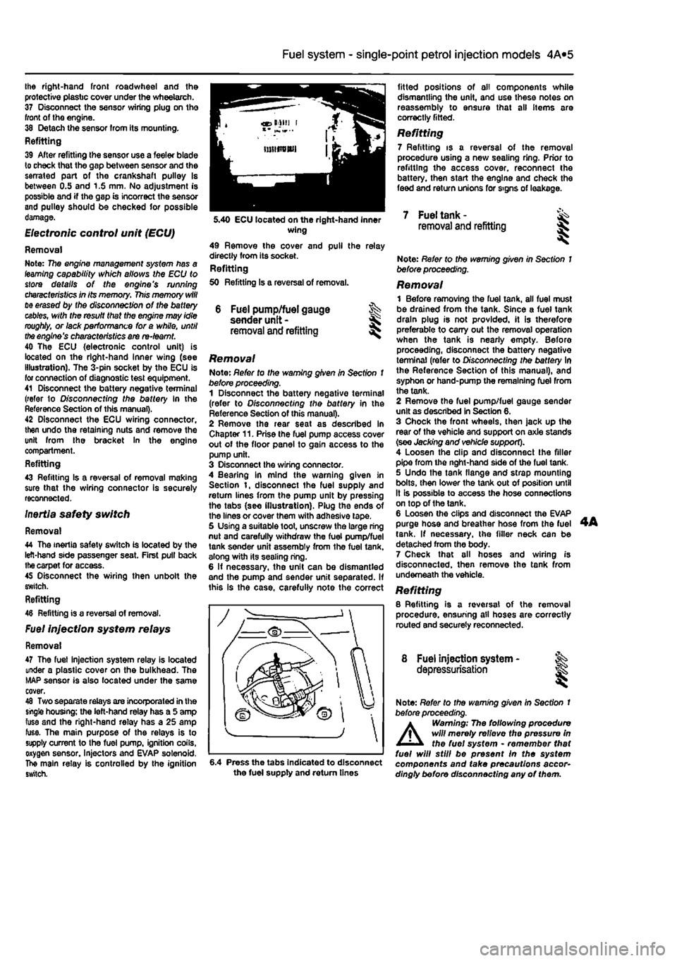
Ihe right-hand front roadwheel and the protective plastic cover under the wheelarch. 37 Disconnect the sensor wiring plug on the front of the engine. 38 Detach the sensor from its mounting. Refitting 39 After refitting Ihe sensor use a feeler blade to check that the gap between sensor and the serrated part of the crankshaft pulley Is between 0.5 and 1.S mm. No adjustment is possible and if the gap is incorrect the sensor and pulley should be checked for possible damage.
Electronic control unit (ECU)
Removal Note: 77ie engine management system has a (earning capability which allows the ECU to store details of the engine's running
characteristics
in its memory,
This
memory
will
tie erased by the disconnection of the battery
cables,
with the resuit that the engine may idle
roughly,
or lack performance for a while, until
the
engine's characteristics are re-teamt. 40 The ECU {electronic control unit) is located on the right-hand Inner wing (see illustration). The 3-pin socket by the ECU is for connection of diagnostic test equipment. 41 Disconnect the battery negative terminal (refer to D/sconnecffng the battery in the Reference Section of this manual). 42 Disconnect the ECU wiring connector, then undo the retaining nuts and remove the unit from the bracket In the engine compartment. Refitting 43 Refitting Is a reversal of removal making sure that the wiring connector is securely reconnected. Inertia safety switch
Removal 44 The inertia safety switch is located by the left-hand side passenger seat. First pull back
the
carpet for access. 45 Disconnect the wiring then unbolt the switch. Refitting 48 Refitting is a reversal of removal.
Fuel injection system relays
Removal 47 The fuel injection system relay is located under a plastic cover on the bulkhead. The MAP sensor is also located under the same cover. 48 Two separate relays are incorporated in the single housing; the left-hand relay has a 5 amp fuse and the right-hand relay has a 25 amp fuse. The main purpose of the relays is to supply current to the fuel pump, ignition coils, oxygen sensor. Injectors and EVAP solenoid. The main relay is controlled by the ignition switch.
4A*2 Fuel system - single-point petrol Injection models
6 Fuel pump/fuel gauge sender unit -removal and refitting
Removal Note: Refer to the warning given in Section 1 before proceeding. 1 Disconnect the battery negative terminal (refer to Disconnecting the battery in the Reference Section of this manual). 2 Remove the rear seat as described in Chapter 11. Prise the fuel pump access cover out of the floor panel to gain access to the pump unit. 3 Disconnect the wiring connector. 4 Bearing in mind the warning given in Section t, disconnect the fuel supply and return lines from the pump unit by pressing the tabs (see illustration). Plug the ends of the lines or cover them with adhesive tape. 5 Using a suitable toot, unscrew the large ring nut and carefully withdraw the fuel pump/fuel tank sender unit assembly from the fuel tank, along with its sealing ring. 6 If necessary, the unit can be dismantled and the pump and sender unit separated. If this is the case, carefully note the correct
fitted positions of oil components while dismantling the unit, and use these notes on reassembly to ensure that all items are correctly fitted.
Refitting 7 Refitting is a reversal of the removal procedure using a new sealing ring. Prior to refitting the access cover, reconnect the battery, then start the engine and check the feed and return unions for signs of leakage.
5.40 ECU located on the right-hand inner wing 49 Remove the cover and pull the relay directly from its socket. Refitting 50 Refitting Is a reversal of removal.
7 Fuel tank -removal and refitting
6.4 Press the tabs Indicated to disconnect the fuel supply and return tines
Note: Refer to the warning given in Section 1 before proceeding.
Removal 1 Before removing the fuel tank, all fuel must be drained from the tank. Since a fuel tank drain plug is not provided, it is therefore preferable to carry out the removal operation when the tank is nearly empty. Before proceeding, disconnect the battery negative terminal (refer to Disconnecting the battery In the Reference Section of this manual), and syphon or hand-pump the remaining fuel from the tank. 2 Remove the fuel pump/fuel gauge sender unit as described in Section 6. 3 Chock the front wheels, then jack up the rear of the vehicle and support on axle stands (see Jacking and vehicle support). 4 Loosen the clip and disconnect the filler pipe from the nght-hand side of the fuel tank. 5 Undo the tank flange and strap mounting bolts, then lower the tank out of position until It is possible to access the hose connections on top of the tank. 6 Loosen the clips and disconnect the EVAP purge hose and breather hose from the fuel tank. If necessary, the filler neck can be detached from the body. 7 Check that all hoses and wiring is disconnected, then remove the tank from underneath the vehicle. Refitting 8 Refitting is a reversal of the removal procedure, ensuring all hoses are correctly routed and securely reconnected.
8 Fuel injection system - ^ depressurisation
Note: Refer to the warning given In Section t before proceeding.
A
Warning; The following procedure will merely relievo the pressure in the fuel system • remember that fuel will still be present In the system components and take precautions accor-dingly before disconnecting any of them.
Page 129 of 225
4A*2 Fuel system -
single-point
petrol Injection models
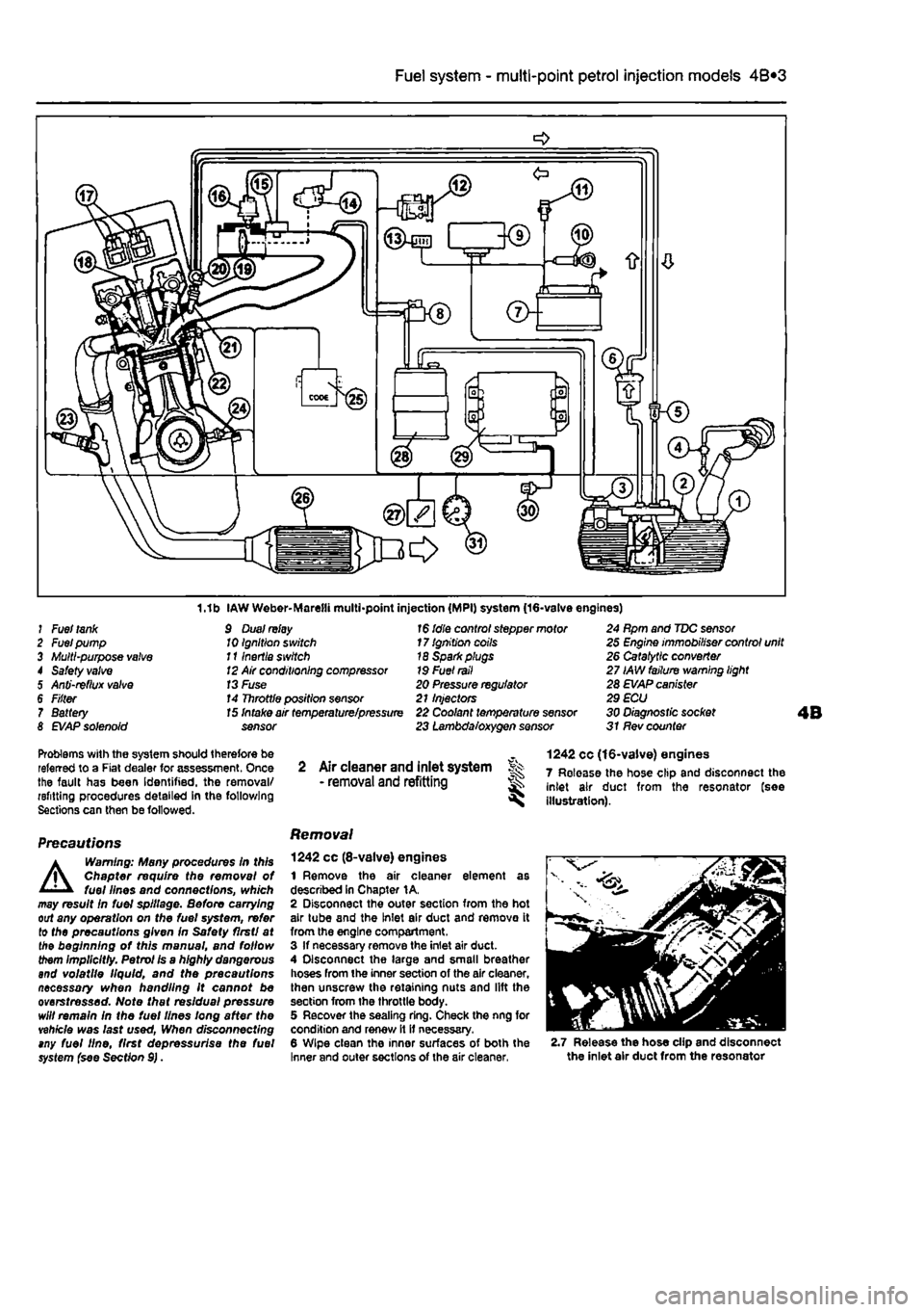
1.1b IAW Weber-Marelli multi-point injection (MPI) system (16-valve engines) J Fuel
tank
2 Fuel pump 3 Multi-purpose
valve
4 Safety
valve
5 Anti-reflux
valve
6 F/fter 7 Battery 8
EVAP
solenoid
9 Dual
relay
10 Ignition switch 111nertia switch
12
Air conditioning compressor
13
Fuse 14 Throttle position sensor
1$
idle control stepper motor 17 Ignition coils 18 Sparkplugs 19 Fuel
rail
20 Pressure regulator 21 Injectors
15
Intake air temperature/pressure 22 Coolant temperature sensor sensor 23 Lambda/oxygen sensor
24 Rpm and TDC sensor 25 Engine immobiliser control unit 26 Catalytic converter 27 IAW failure warning light 28 EVAP canister 29 ECU 30 Diagnostic socket 31 Rev counter
Problems with the system should therefore be referred to a Fiat dealer for assessment. Once the fault has been Identified, the removal/ refitting procedures detailed in the following Sections can then be followed.
Precautions
A
Warning: Many procedures In this Chapter require the removal of fuel lines and connections, which may result In fuel spillage. Before carrying out any operation on the fuel system, refer to the precautions given In Safety flrstl at the beginning of this manual, and follow them implicitly. Petrol Is a highly dangerous and volatile liquid, and the precautions necessary when handling it cannot be overstressed. Note that residual pressure will remain in the fuel lines long after the vehicle was last used, When disconnecting tny fuel line, first depressurise the fuel system {see Section 9).
2 Air cleaner and inlet system Sk - removal
and
refitting ^
Removal
1242 cc (8-valve) engines 1 Remove the air cleaner element as described In Chapter 1A. 2 Disconnect the outer section from the hot air tube and the Inlet air duct and remove it from the engine compartment. 3 If necessary remove the inlet air duct. 4 Disconnect the large and small breather hoses from the inner section of the air cleaner, then unscrew the retaining nuts and lift the section from the throttle body. 5 Recover the sealing ring. Check the nng for condition and renew it it necessary. 6 Wipe clean the inner surfaces of both the Inner and outer sections of the air cleaner,
1242 cc (16-valve) engines 7 Release the hose clip and disconnect the inlet air duct from the resonator (see illustration).
2.7 Release the hose clip and disconnect the inlet air duct from the resonator
Page 134 of 225
4A*2 Fuel system -
single-point
petrol Injection models
Refitting 37 Refitting Is a reversal of removal making sure that the wiring connector is securely reconnected.
Inertia safety switch 36 Refer to Chapter 4A, Fuel injection system relays Removal 39 The fuel injection system twin relay Is located under a plastic cover on the engine compartment bulkhead. 40 The main purpose of the relay Is to supply current to the fuel pump, ignition coils, oxygen sensor, Injectors and EVAP solenoid. The relay is controlled by the ignition switch. A15 amp fuse, protecting ihe fuel pump, oxygen sensor and EVAP solenoid is located adjacent to the relay. 41 Remove the cover and pull the relay directfy from Its socket. Refitting 42 Refitting is a reversal of removal.
7 Fuel pump and fuel gauge sender unit - JK removal
and
refitting ^
Removal Note: Refer fo (he warning given in Section 1 before proceeding. 1 Disconnect the battery negative terminal (refer to Disconnecting the battery In the Reference Section of this manual). 2 Depreasurise the fuel system as described in Section 9. 3 Remove the rear soat as described In Chapter 11. Prise the fuel pump access cover out of the floor panel to gain access to the pump unit. On later models, undo the three retaining screws to release the cover. 4 Disconnect the wiring connector. 5 Bearing In mind the warning given In Section t, disconnect Ihe fuel supply and, where applicable, the return lines from tho pump unit by pressing the tabs. Plug the ends of the lines or cover them with adhesive tape. 6 Using a suitable tool, unscrew the large ring nut and carefully withdraw the fuel pump/fuel tank sender unit assembly from the fuel tank, along with its sealing rtng. 7 If necessary, the unit can be dismantled and the pump and sender unit separated. If this is (he case, carefully note the correct fitted positions of all components while dismantling the unit, and use these notes on reassembly to ensure that all items are correctly fitted.
Refitting 8 Refitting is a reversal of the removal procedure using a new sealing ring. Prior to refitting the access cover, reconnect the battery, then start the engine and check the fuel line unlon(s) (or signs of i
Fuel
tank -removal and refitting
Refer to Chapter 4A.
9 Fuel injection system -depressurisatton
Note: Refer to the warning given In Section 1 before proceeding.
A
Warning: The following procedure will merely relieve the pressure In the fuel system • remember that fuel will still be present In the system components and take precautions accord-ingly before disconnecting any of them. 1 The fuel system referred to in this Section is defined as the lank-mounted fuel pump, tha fuel filter, the fuel rail, the fuel injectors, and the metal pipes and flexible hoses of the fuel lines between these components. All these contain fuel which will be under pressure while the engine Is running and/or while the Ignition is switched on. The pressure will remain for some time after the Ignition has been switched off. and must be relieved before any of these components are disturbed for servicing work. 2 Disconnect the battery negative terminal (refer to Disconnecting the battery In the Reference Section of this manual). 3 Have a large rag ready to cover the union to be disconnected and, if possible, place a con-tainer beneath the relevant connection/union. 4 Slowly loosen the connection or union nut (as applicable) to avoid a sudden release of pressure, and ensure that the rag is wrapped around the connection to catch any fuef spray which may be expelled. Once the pressure is released, disconnect the fuel line, and Insert plugs to minimise fuel loss and prevent the entry of dirt Into the fuel system. Note that on later models, quick-release fuel couplings are used on many of the fuel line connections. To release these couplings, depress the two clips on the side of the coupling while keeping the fuel line pushed In. With the clips depressed, slowly withdraw the fuel line from the coupling allowing the fuel pressure to release, then withdraw the fuel line fully.
10 Inlet manifold-removal
and
refitting
Note: Refer fo the warning given in Section 1 before proceeding.
1242 cc (8-valve) engines
Removal 1 Remove ihe throttle body assembly as described in Section 5.
2 Remove the fuel rail and injectors at described in Section 5. 3 Drain the cooling system ss described n Chapter 1A. 4 Disconnect the wiring connector from ih* coolant temperature sensor (situated on it* left-hand side of the manifold). 5 Undo the bolt securing the accelerator cable mounting bracket to the manifold, am position it clear of the manifold. 6 Slacken the retaining clip and disconnect the coolant hose from the rear of the mandold 7 Disconnect the brake vacuum hose, 6 Undo the seven manifold retaining nuisw bolts, and remove the manifold from tta engine. Remove the gasket and discard tti new one should be used on refitting. Refitting
9 Refitting is a reverse of the removjf procedure, noting the following points: a) Ensure that the manifold and cylinder lim mating surfaces are dean and
dry.
and fill new manifold gasket. Refit the
manifold
and securely tighten Its retaining
nuts.
b) Ensure all relevant hoses are recorwscfed fo their original positions and are
sacurtfy
held (Where necessary; by the
retaining
clips. c) Refit the fuel rail and injectors, and
the
throttle body assembly with
reference to
Sect/on 5. d) On completion, refill the cooling
system
as described in Chapter 1A. 1242 cc (16-valve) engines
Removal 10 Disconnect the battery negative ternnncf (refer to Disconnecting the battery in ths Reference Section of this manual). 11 Remove the resonator, air cleaner and inlet air duct as described In Section 2. 12 Drain the cooling system as described r, Chapter 1A. 13 Free the accelerator inner cable from IN throttle cam. remove the outer cable spring dip. then pull the outer cable out from itt mounting bracket rubber grommet. 14 From the side of the throttle boOf, disconnect the wiring connectors from the throttle potentiometer and the Idle contrd stepper motor. Disconnect the coolant temperature sensor wiring connector located in the Inlet manilold below the throttie bodr, and disconnect the brake servo vacuum hose. 15 Disconnect Ihe wiring connectors for the fuel in|ector harness and the Intake a* temperature/pressure sensor, thtn disconnect the fuel pressure regulator vacuum hose and the EVAP purge valve
hose
(see illustration). 16 Undo Ihe two bolts securing the plastic Inlet manifold upper section to the lower section. Release the spark plug HT lead from the location groove in the manifold upper section, then lift Ihe upper section, complete with throttle body, off the engine. Recover
the
O-rings from the manifold pons.
Page 157 of 225
5C«2 Preheating system - diesel models
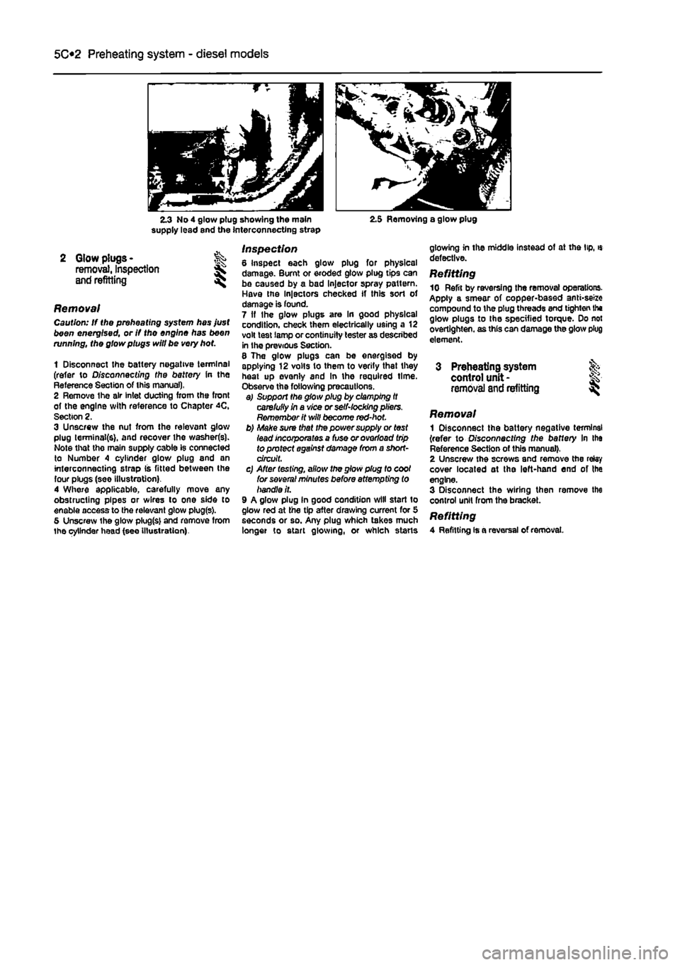
2.3 No 4 glow plug showing the main supply lead end the interconnecting strap 2.5 Removing a glow plug
2 Glow plugs -removal, Inspection and refitting
Removal Caution: If the preheating system has just been energised, or If tho engine has been running, the glow plugs will be very hot
1 Disconnect the battery negative terminal (refer to Disconnecting the battery in the Reference Section of this manual), 2 Remove Ihe air Inlet ducting from the front of the engine with reference to Chapter 4C, Section 2. 3 Unscrew the nut from the relevant glow plug lerminai(s). and recover the washer(s). Note that tho main supply cable is connected to Number 4 cylinder glow plug and an interconnecting strap lis fitted between the four plugs (see Illustration). 4 Where applicable, carefully move any obstructing pipes or wires lo one side to enable access to the relevant glow plug(s). 5 Unscrew the glow plug(s) and remove from the cylinder head (see illustration).
Inspection 8 Inspect each glow plug for physical damage. Burnt or eroded glow plug tips can bo caused by a bad Injector spray pattern. Have the Injectors checked if this sort of damage is found. 7 If Ihe glow plugs are In good physical condition, check them electrically using a 12 volt test lamp or continuity tester as described in the previous Section. 8 The glow plugs can be energised by applying 12 volts to them to verity that they heat up evenly and In the required time. Observe the following precautions. a) Support the glow plug by clamping it carefully in a vice or selNocking pliers. Remember it will become red-hot. b) Make sura that the power supply or test lead incorporates a fuse or overload trip to protect against damage from a short-circuit. c) After testing, allow the glow plug to cool for several minutes before attempting to handle it. 9 A glow plug In good condition will start to glow red at the tip after drawing current for 5 seconds or so. Any plug which takes much longer to start glowing, or which starts
glowing in the middle instead of at the lip, « defective. Refitting 10 Refit by reversing the removal operations. Apply a smear of copper-based anti-seize compound to the plug threads and tighten Ihe glow plugs to Ihe specified torque. Do not overtighten, as this can damage the glow plug element.
3 Preheating system control unit -removal
and
refitting I
Removal 1 Disconnect the battery negative terminal (refer to Disconnecting the baffery In Ihe Reference Section of this manual). 2 Unscrew the screws and remove the relay cover located at the left-hand end of the engine. 3 Disconnect the wiring then remove the control unit from the bracket. Refitting 4 Refitting is a reversal of removal.
Page 165 of 225
7A«4 Manual transmission
33 Remove lha air cleaner front section and air ducting with reference to Chapter 4C. Also disconnect the injection pump vacuum pipe from the clips on the left-hand end of the cylinder head. This work is necessary in order to fit the engine hoist 34 Support the weight of the engine using a hoist attached to the engine lifting eyes, or alternatively use a trolley Jack and block of wood beneath the engine. 35 Unscrew the nuts securing the downpipe to the exhaust manifold, then lower it and support on an axle stand. Recover the gasket. 36 Unscrew the starter motor mounting bolts and support the starter motor to one side. 37 Disconnect the wiring from the reversing light switch on the front of the transmission. 38 Unscrew the nut and disconnect the earth cable from its stud. 39 Trace the wiring back from the electronic speedometer sensor and disconnect the connector located on the left-hand side ot the engine. If a mechanical speedometer Is fitted unscrew the knurled collar and disconnect the cabte from the transmission. 40 Unbolt and remove the transmission lower cover. 41 Using an Allen key unscrew the bolts securing the inner end of the left-hand driveshaft to the transmission flange. Remove the bolts and recover the spacer plates. Support the driveshaft on an axle stand. 42 Unscrew and remove the bolts securing the left-hand swivel hub assembly to the front suspension strut, then separate the components and support the swivel hub on an axle stand. 43 Move the swrvel hub assembly outwards and support the driveshaft away from Ihe transmission. 44 Using an Allen key unscrew the bolts securing the Inner end of the right-hand driveshaft to the intermediate shaft flange. Remove the bolts and recover the spacer plates. Support the driveshaft on an axle stand. 45 Remove the intermediate driveshaft with reference to Chapter 8. 46 Working beneath the vehicle, unscrew the bolts securing the rear engine mounting to the underbody then unscrew the bolts securing the mounting to the transmission and withdraw the mounting assembly from under the vehicle.
47 Unscrew the bolts securing the left-hand engine/transmission mounting to the body then unscrew Ihe bolts from the transmission and remove the mounting. 48 Support the weight of the transmission on a trolley jack then unscrew the remaining nut and bolts from the bellhousing and pull the transmission away from the engine.
A
Warning: Support the trans-mission to ensure that It remains steady o/i the jack head. Keep the transmission level until the Input shaft
1$
fully withdrawn from the clutch friction plate.
Refitting 48 Refitting is a reversal of the removal procedure, but note the following points. a) Appiy a smear* of high-meiting-point grease to the clutch friction piate splines; take care to avoid contaminating the friction surfaces. b) Tighten all bolts to the specified torque. c) Fit new clips to secure the driveshaft gaiters to the transmission output shafts. d) Adjust the clutch cable (where applicable) as described In Chapter 6.
4 Manual transmission overhaul -general Infomtatlon
Overhauling a manual transmission is a difficult and Involved Job for the DIY home mechanic. In addition to dismantling and reassembling many small parts, clearances must be precisely measured and, if necessary, changed by selecting shims and spacers. Internal transmission components are also often difficult to obtain, and in many Instances, extremely expensive. Because of this, If the transmission develops a fault or becomes noisy. Ihe best course of action is to have the unit overhauled by a specialist repairer, or to obtain an exchange reconditioned unit. Nevertheless, it is not impossible for the more experienced mechanic to overhaul the transmission, provided the special tools are available, and the Job is done in a deliberate step-by-step manner, so that nothing is overlooked.
The tools necessary for an overhaul include internal and external clrclip pliers, bearing pullers, a slide hammer, a sat of pin punches, a dial test Indicator, and possibly a hydraulic press. In addition, a large, sturdy workbench 8od a vice will be required. During dismantling o1 the transmission, make careful notes of how each component
1$
fitted, to make reassembly easier and more accurate. Before dismantling the transmission, it will help if you have some idea what area is malfunctioning. Certain problems can be closely related to specific areas In the transmission, which can make component examination and replacement easier. Refer to the Fault Finding Section at the end of this manual for more Information.
5 Reversing light switch -testing, removal and refitting ||
Testing 1 The reversing light circuit is controlled by a plunger-type switch screwed into the front of the transmission casing. If a fault develops, first ensure that Ihe circuit fuse has not blown. 2 To test the switch, disconnect the wiring connector, and use a multimeter (set to the resistance function) or a battery-and-bulb test circuit to check that there is continuity between the switch terminals only when reverse gear is selected. If this is not the case, and there are no obvious breaks or other damage to the wires, the switch is faulty, and must be renewed.
Removal 3 Access to the reversing light switch Is best achieved from under the vehicle. Apply the handbrake then jack up Ihe front of the vehicle and support on axle stands (see Jacking and vehicle support). 4 Disconnect the wiring connector, then unscrew It from the transmission casing.
Refitting 5 Refit the switch and tighten securely. 6 Reconnect the wiring then lower the vehicle to the ground.
Page 204 of 225
Bodywork and fittings
11
*3
several blobs of filler paste around its periphery. Aluminium tape should be used for small or very narrow holes. Pull a piece off the roll, trim it to the approximate size and shape required, then pull off the backing paper (if used) and stick the tape over the hole; it can be overlapped if the thickness of one piece is Insufficient. Burnish down the edges of the tape with the handle of a screwdriver or similar, to ensure that the tape is securely attached to the metal underneath.
Bodywork repairs -filling and respraying Before using this Section, see the Sections on dent, deep scratch, rust holes and gash repairs. Many types of bodyfiller are available, but generally speaking, those proprietary kits which contain a tin of filler paste and a tube of resin hardener are best for this type of repair. A wide, flexible plastic or nylon applicator will be found invaluable for imparting a smooth and well-contoured finish to the surface of the filler. Mix up a little filler on a clean piece of card or board • measure the hardener carefully (follow the maker's instructions on the pack), otherwise the filler will set too rapidly or too slowly. U3ing the applicator, apply the filler paste to the prepared area; draw the applicator across the surface of the filler to achieve the correct contour and to level the surface. As soon as a contour that approximates to the correct one is achieved, stop working the paste - if you carry on too long, the paste will become sticky and begin lo 'pick-up' on the applicator. Continue to add thin layers of filler paste at 20-minute Intervals, until the level of the filler is just proud of the surrounding bodywork. Once the filler has hardened, the excess can be removed using a metal plane or file. From then on, progressively-finer grades of abrasive paper should be used, starting with a 40-grade production paper, and finishing with a 400-grade wet-and-dry paper. Always wrap the abrasive paper around a flat rubber, cork, or wooden block • otherwise the surface of the filler will not be completely flat. During the smoothing of the filler surface, the wet-and-dry paper should be periodically rinsed in water. This will ensure that a very smooth finish is imparled to the filler at the final stage. At this stage, the dent should be surrounded by a ring of bare metal, which in turn should be encircled by the finely feathered' edge of the good paintwork. Rinse the repair area with clean water, until all of the dust produced by the rubbing-down operation has gone. Spray the whole area with a light coat of primer - this will show up any imperfections In the surface of the filler. Repair these imperfections with fresh filler paste or bodystopper, and once more smooth the surface with abrasive paper. Repeat this
spray-and-repair procedure until you are satisfied that the surface of the filler, and the feathered edge of the paintwork, are perfect. Clean the repair area with clean water, and allow to dry fully.
flflfl^gl tf txxfystopper is used, it can WiMiiBi be mixed with cellulose Hi NT thinners to form a really thin 1 1 paste which is Ideal for filling small holes.
The repair area Is now ready for final spraying. Paint spraying must be carried out in a warm, dry, windless and dust-free atmosphere. This condition can be created artificially if you have access to a large indoor working area, but If you are forced to work in the open, you will have to pick your day very carefully. If you are working indoors, dousing the floor In the work area with water will help to settle the dust which would otherwise be in the atmosphere. If the repair area is confined to one body panel, mask off the surrounding panels; this will help to minimise the effects of a slight mis-match in paint colours. Bodywork fittings (eg chrome strips, door handles etc) will also need to be masked off. Use genuine masking tape, and several thicknesses of newspaper, for the masking operations. Before commencing to spray, agitate the aerosol can thoroughly, then spray a test area (an old tin. or similar) until the technique is mastered. Cover the repair area with a thick coat of primer; the thickness should be built up using several thin layers of paint, rather than one thick one. Using 400-grade wet-and-dry paper, rub down the surface of the pnmer until it is really smooth. While doing this, the work area should be thoroughly doused with water, and the wet-and-dry paper periodically rinsed in water. Allow to dry before spraying on more paint. Spray on the top coat, again building up the thickness by using several thin layers of paint. Start spraying at one edge of the repair area, and then, using a side-to-side motion, work until the whole repair area and about 2 inches of the surrounding original paintwork is covered. Remove all masking material 10 to 15 minutes after spraying on the final coat of paint. Allow the new paint at least two weeks to harden, then, using a paintwork renovator, or a very fine cutting paste, blend the edges of the paint into the existing paintwork. Finally, apply wax polish.
Plastic components With the use of more and more plastic body components by the vehicle manufacturers (eg bumpers, spoilers, and in some cases major body panels), rectification of more serious damage to such items has become a matter of either entrusting repair work to a specialist in this field, or renewing complete components. Repair of such damage by the
DIY owner is not really feasible, owing to the cost of the equipment and materials required for effecting such repairs. The basic technique involves making a groove along the line of the crack in the plastic, using a rotary burr In a power drill. The damaged part is then welded back together, using a hot-air gun to heat up and fuse a plastic filler rod Into the groove. Any excess plastic is then removed, and the area rubbed down to a smooth finish. It is important that a filler rod of the correct plastic is used, as body components can be made of a variety of different types (eg polycarbonate, ABS, polypropylene). Damage of a less senous nature (abrasions, minor cracks etc) can be repaired by the DIY owner using a two-part epoxy filler repair material. Once mixed in equal proportions, this is used in similar fashion to the bodywork filler used on metal panels. The filler is usually cured in twenty to thirty minutes, ready for sanding and painting. If the owner is renewing a complete component himself, or If he has repaired it with epoxy filler, he will be left with the problem of finding a suitable paint for finishing which is compatible with the type of plastic used. At one time, the use of a universal paint was not possible, owing to the complex range of plastics encountered In body component applications. Standard paints, generally speaking, will not bond to plastic or rubber satisfactorily. However, it is now possible to obtain a plastic body parts finishing kit which consists of a pre-pnmer treatment, a primer and coloured top coat. Full Instructions are normally supplied with a kit, but basically, the method of use is to first apply the pre-pnmer to the component concerned, and allow It to dry for up to 30 minutes. Then the primer is applied, and left to dry for about an hour before finally applying the special-coloured top coat. The result is a correctly-coloured component, where the paint will flex with the plastic or rubber, a property that standard paint does not normally possess.
5 Major body damage -repair
Where serious damage has occurred, or large areas need renewal due to neglect, it means that complete new panels will need welding-in, and this is best left to professionals. If the damage is due to Impact, it will also be necessary to check completely the alignment of the bodyshell, and this can only be carried out accurately by a Fiat dealer using special jigs. If the alignment of the bodyshell is not corrected, the car's handling may be seriously affected. In addition, excessive stress may be Imposed on the steering, suspension, tyres or transmission, causing abnormal wear or even complete failure.
Page 213 of 225
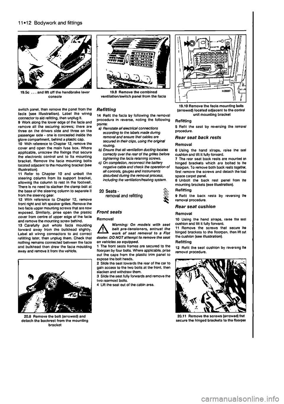
11 *12 Bodywork and fittings
switch panel, then remove the panel from the facia (see illustration). Label tho wiring connector to aid refitting, then unplug It. 0 Work along the lower edge of Ihe facia and remove all the securing screws; there are three on the drivers side and three on the passenger side - one is concealed inside the glove compartment, behind a plastic cap. 10 Wilh reference to Chapter 12, remove the cover and open the main fuse box. Where applicable, unscrew the fixings that secure the electronic control unit to Its mounting bracket. Remove the facia mounting bolts located adjacent to the mounting bracket (see illustration). 11 Refer to Chapter 10 and unbolt the steering column from Its support bracket, allowing the column to rest in the footwell. There is no need to slacken the clamp bolt at Ihe base of the steering column to separate it from the steering gear. 12 With reference to Chapter 12, remove front right and left speaker grilles. Remove the two facis upper mounting screws ihat are now exposed. Similarly, prise open the plastic cover from centre of upper edge of the fada and remove the mounting screw behind. 13 Carefully pull whole facia moulding forward away from tho bulkhead slightly. Label all wiring connectors to aid correct refitting later, then unplug Ihem. Check that nothing remains connected between the facia and bulkhead then draw the facia moulding away and remove It from the vehicle.
20.8 Remove the bolt (arrowed) and detach the backrest from the mounting bracket
Refitting 14 Refit the facia by following the removal procedure in reverse, noting the following points: a) Reinstate all electrical connections according to (he labels made during removal and ensure that cables are secured in their clips, using the origins/ routing. b) Ensure thai all ventilation ducting locates correctly over the rear of the grilles before tightening the facia retaining screws. c) On completion, reconnect the battery negative cable and chock the operation of all controls, gauges and Instruments disturbed during the removal process, Including the ventilation/heating system.
20 Seats -removal and refitting JS:
Front seats
Removal
A
Warning: On models with seat belt pre-tonsionors, entrust the work of seat removal to a Flat dealer. DQNOTattempt to remove the seat on vehicles so equipped. 1 The front seats frames are secured to the fioorpan by four bolts. Whero applicable, prise out the caps from the plastic trim panel lo expose the bolt heads. 2 Slide the seat towards the rear of the car to gain access to the two bolts at the front, Ihen slacken and withdraw them. 3 Slide Ihe seat fully forwards and remove the two rearmost bolls. 4 Ufl the seat out of the cabin area.
(arrowed) located adjacent to the control unit mounting bracket Refitting 5 Refil the seat by reversing the remove! procedure. Rear seat back rests
Removal 6 Using the hand straps, raise the seal cushion and lilt it fully forward. 7 The rear seat back rests are mounted or hinged brackets which aro boiled to Ihe fioorpan. To remove both back rests together, first remove the screws and detach the load space carpet panel. 8 Unbolt the back rest panel from the mounting brackets (see illustration). Refitting 9 Refit tho back rests by reversing Ihe removal procedure. Rear seat cushion
Removal 10 Using the hand straps, raise the seat cushion and tilt it fully forward. 11 Remove ihe screws Ihat secure Ihe hinged brackets to tho fioorpan. then lift out the cushion (see illustration}. Refitting 12 Refit the seat cushion by reversing Ihe removal procedure.
20.11 Remove the screws (arrowed) that secure the hinged brackets to the fioorpan
Page 214 of 225
10*1
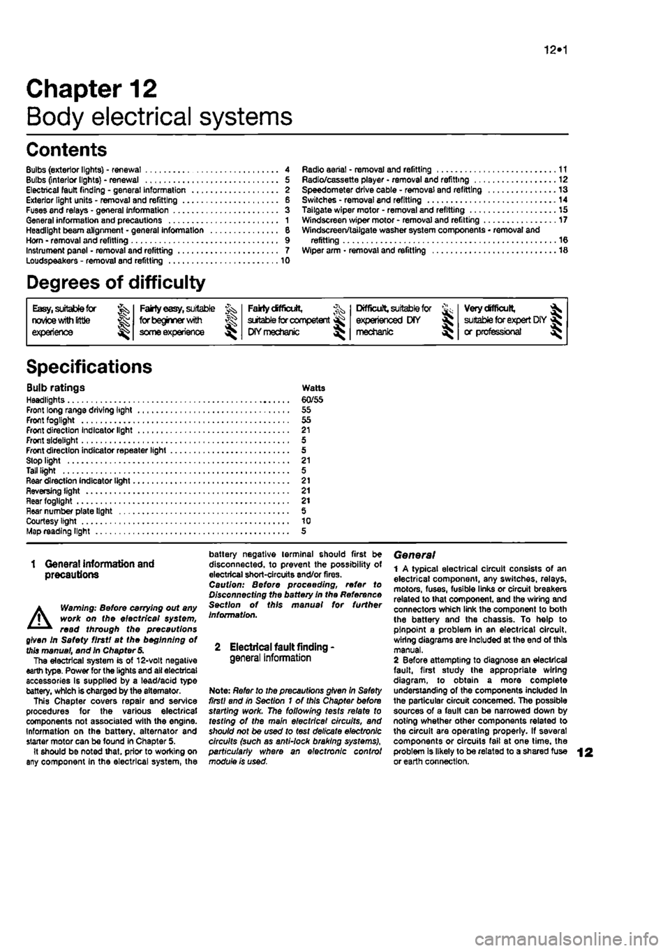
Chapter 12
Body electrical systems
Contents
Bulbs (exterior lights) - renewal 4 Bulbs (interior lights) - renewal 5 Electrical fault finding - general information 2 Exterior light units - removal and refitting 6 Fuses and relays - general Information 3 General information and precautions 1 Headlight beam alignment • general Information 6 Horn • removal and refitting 9 Instrument panel - removal and refitting 7 Loudspeakers - removal and refitting 10
Degrees of difficulty
Radio aerial - removal and refitting 11 Radio/cassette player • removal and refitting 12 Speedometer drive cable - removal and refitting 13 Switches - removal end refitting 14 Tailgate wiper motor - removal and refitting 15 Windscreen wiper motor - removal and refitting 17 Windscreen/tailgate washer system components • removal and refitting 16 Wiper arm • removal and refitting 18
Easy,
statable for ^
novice with liffle
|| experience ^
Fairly
easy,
suitable for beginner with ^ some experience ^
Fabtycffficiit,
suitable
for competent ^
DIY
mechanic ^
Difficult, suitable for
^ experienced DIY JR mechanic
Very difficult,
A,
suitable
for
expert DIY
Sj or professional ^
Specifications
Bulb ratings Watts Headlights 60/55 Front long range driving light 55 Front fogllght 55 Front direction Indicator light 21 Front sidelight 5 Front direction indicator repeater light 5 Stop light 21 Tall light 5 Rear direction indicator light 21 Reversing light 21 near fogllght 21 Hear number plate light 5 Courtesy light 10 Map reading light 5
1 Genera! information and precautions
A
Warning: fie/Ore carrying out any work on the electrical system, read through the precautions given in Safety first! at the beginning of this manual, and in Chapter 8. The electrical system is of 12-volt negative earth type. Power for the lights and all electrical accessories is supplied by a lead/acid type battery, which is charged by the alternator. This Chapter covers repair and service procedures for the various electrical components not associated with the engine. Information on the battery, alternator and starter motor can be found in Chapter 5. It should be noted that, prior to working on any component In the electrical system, the
battery negative terminal should first be disconnected, to prevent the possibility of electrical short-circuits and/or fires. Caution: Before proceeding, refer to Disconnecting the battery In the Reference Section of this manual for further information.
2 Electrical fault finding-general information
Note: Refer to the precautions given In Safety first! and in Section 1 of this Chapter before starting work. The following tests relate to testing ot the main electrical circuits, and should not be used to test delicate electronic circuits (such as antHock braking systems), particularly where an electronic con fro/ module is used.
General 1 A typical electrical circuit consists of an electrical component, any switches, relays, motors, fuses, fusible links or circuit breakers related to that component, and the wiring and connectors which link the component to both the battery and the chassis. To help to pinpoint a problem in an electrical circuit, wiring diagrams are Included at the end of this manual. 2 Before attempting to diagnose an electrical fault, first study the appropriate wiring diagram, to obtain a more complete understanding of the components included In the particular circuit concerned. The possible sources of a fault can be narrowed down by noting whether other components related to the circuit are operating properly. If several components or circuits fait at one time, the problem Is likely to be related to a shared fuse or earth connection.