lock FIAT PUNTO 1998 176 / 1.G Owners Manual
[x] Cancel search | Manufacturer: FIAT, Model Year: 1998, Model line: PUNTO, Model: FIAT PUNTO 1998 176 / 1.GPages: 225, PDF Size: 18.54 MB
Page 167 of 225
7B*2 Automatic transmission
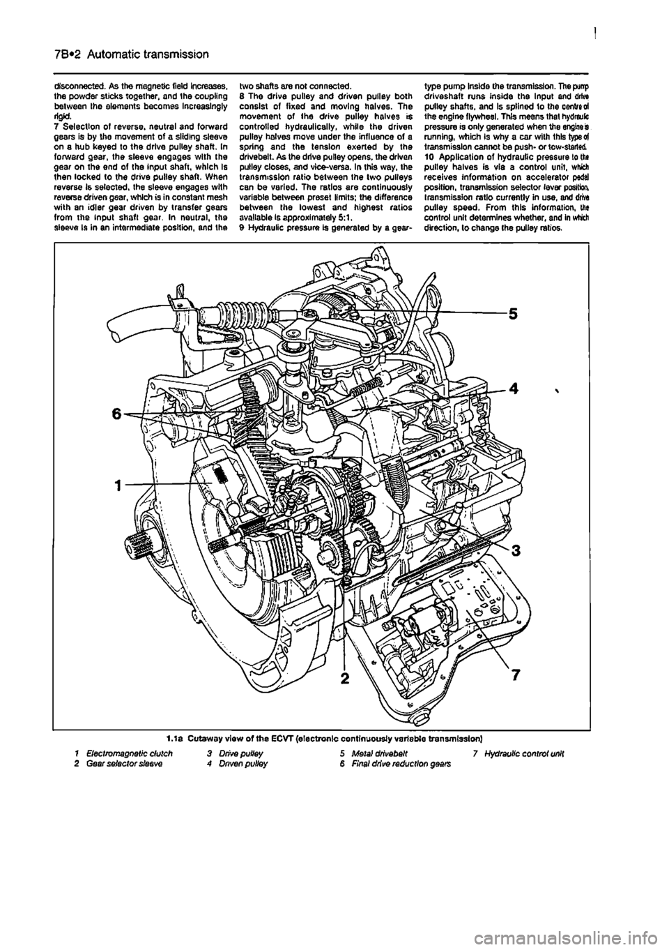
disconnected. As the magnetic field increases, the powder sticks together, and the coupling between Ihe elements becomes Increasingly rigid. 7 Selection of reverse, neutral and forward gears is by the movement of a sliding sleeve on a hub keyed to the drive pulley shaft. In forward gear, the sleeve engages with the gear on the end of the input shaft, which is then locked to the drive pulley shaft. When reverse is selected, the sleeve engages with reverse driven gear, which is in constant mesh with an idler gear driven by transfer gears from the input shaft gear. In neutral, the sleeve Is in an intermediate position, and the
two shafts are not connected. 8 Tho drive pulley and driven pulley both consist of fixed and moving halves. The movement of ihe drive pulley halves is controlled hydraulically, while the driven pulley halves move under the influence of a spring and the tension exerted by the drivebeit. As the drive pulley opens, the driven pulley closes, and vice-versa. In this way, the transmission ratio between the two pulleys can be varied. The ratios are continuously variable between preset limits; the difference between the lowest and highest ratios available is approximately 5:1. 9 Hydraulic pressure is generated by a gear-
type pump Inside the transmission. The punp driveshaft runs inside the Input and drive pulley shafts, and Is splined to the centred the engine flywheel. This means that hydreulc pressure is only generated when the engine is running, which is why a car with this type ot transmission cannot be push- or tow-started 10 Application of hydrautic pressure to the pulley halves is via a control unit, which receives information on accelerator pedal position, transmission selector lever position, transmission ratio currently in use, and drive pulley speed. From this information, the control unit determines whether, and in which direction, lo change the pulley ratios.
1.1 a Cutaway view of the ECVT (electronic continuously variable transmission) 7 Electromagnetic dutch 3 Drive pulley 5 Metal drivebeit 7 Hydraulic controt unit 2 Gear selector sleeve A Dnven pulley 6 Final drive reduction gears
Page 169 of 225
7B*4 Automatic transmission
2 Automatic transmission - ^ removal and refitting St
Removal 1 Select a solid, level surface to park the vehicle upon. Give yourself enough space to move around it easily. Apply the handbrake then jack up the front of the vehicle and support on axle stands (see Jacking and vehicle support). Remove both front wheels, 2 Remove the battery and mounting tray as described In Chapter 5A. 3 Remove the air cleaner and air inlet duct as described In Chapter 4A. 4 Disconnect the kickdown cable at the sector on the throttle housing and detach It from the mounting on the camshaft cover. Also release the cable from the support on the left-hand end of the cylinder head. 5 Disconnect the wiring connectors on the transmission. 6 Disconnect the fluid inlet and outlet Unas from the heat exchanger on top of the transmission. 7 Pull the fluid level dipstick from Its tube on the front of the transmission and tape over the top of the tube to prevent dirt entry. 8 Unscrew and remove the retaining pin and disconnect the speed selector cable from the top of the transmission. 9 Unscrew the upper bolt securing the starter motor to the transmission. 10 Unscrew the upper bolts securing the transmission to the engine. 11 Support the weight of the engine using a hoist attached to the engine lifting eyes, or alternatively UBO a trolley jack and block of wood beneath the engine, 12 Remove the screws and remove the front wheel arch liner from under the left-hand wheel arch. 13 Unscrew the nut securing the earth cablo to the transmission. 14 Using a punch drive out the roll pins securing both driveshafts to the final drive output shafts. 15 Unscrew and remove the bolts securing the left-hand swivel hub assembly to the front suspension strut, then separate the components and support the swivel hub on an axle stand. 16 Move the swivel hub assembly outwards and slide the inner end of the driveshaft from the splines on the transmission output shaft. Support the shaft away from the transmission to prevent damage to the gaiters. 17 Unscrew the lambdafoxygen sensor from the exhaust downpipe and position it In a safe place to prevent damage. 18 Unscrew ihe nuts securing the downpipe to Ihe exhaust manifold, then lower It and suppon on an axle stand. Recover the gasket. 19 Unscrew the knurled nut and disconnect the speedometer cable from the top of the final drive housing.
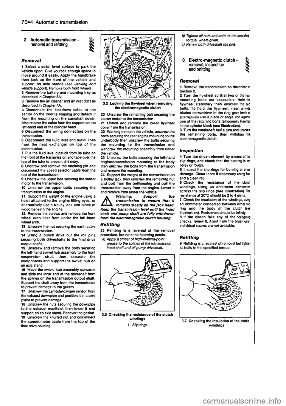
3-2 Locking the flywheel when removing the electromagnetic clutch 20 Unscrew the remaining bolt securing the staner motor to the transmission 21 Unbolt and remove Ihe lower flywheel cover from the transmission. 22 Working beneath the vehicle, unscrew the bolts securing the rear engine mounting to the underbody then unscrew the bolts securing the mounting lo the transmission and withdraw the mounting assembly from under the vehicle. 23 Unscrew the bolts securing the left-hand engine/transmission mounting to the body thon unscrew the bolts from the transmission and remove the mounting. 24 Support the weight of the transmission on a trolley jack then unscrew the remaining nut and bolt from the bellhouslng and pull the transmission away from the engine. Lower it and remove from under the vehicle.
A
Warning: Support the transmission to ensure that It remains steady on the Jack head. Keep the transmission level until the Input shaft and pump shaft are fully withdrawn from the electromagnetic clutch housing.
Refitting 25 Refitting is a reversal of the removal procedure, but note the following points. a} Apply a smear of high-melting-point grease to the splines of the transmission input shaft and oil pump driveshaft.
3.6 Checking the resistance of the clutch windings 1 Slip rings
0) Tighten all nuts and bolts to the
specified
torque, where given, c) Renew both driveshaft roll pins.
3 Electro-magnetic clutch • & removal, inspection 5. and refitting ^
Removal 1 Remove Ihe transmission as described n Section 2. 2 Turn the flywheel so that two of the lour mounting bolts are accessible, Hold tha flywheel stationary then unscrew Ihe tvrt bolts. To hold the flywheel, Insert a wida bladed screwdriver In the ring gear teeth or alternatively use a piece of angle iron against one of the retaining bolts temporarily Inserted in the cylinder block (see illustration). 3 Turn the crankshaft half a turn and unscrew the remaining bolts, then withdraw the electromagnetic clutch.
Inspection 4 Turn the driven element by means of tha slip rings, and check that the bearing is not noisy or rough. 5 Inspect the slip rings for burning or other damage. Clean them if necessary using fid and a clean rag. 6 Check the resistance of the clutch windings, using an ohmmetor connected across the slip rings (see Illustration). The resistance at 20*0 should be 2 to 4 ohms. 7 Check the Insulation of the windings, using an ohmmeter connected between either sip ring and the body of the clutch (see illustration). Resistance should be Infinity. 8 If the clutch fails any of the foregoing checks, renew it. Apart from the brush gear, Individual spares are not available.
Refitting 9 Refitting is a reversal of removal but tighten all bolts to the specified torque.
windings
Page 170 of 225
Automatic transmission 7B«5
4 Electro-magnetic dutch brushes - removal, inspection and refitting
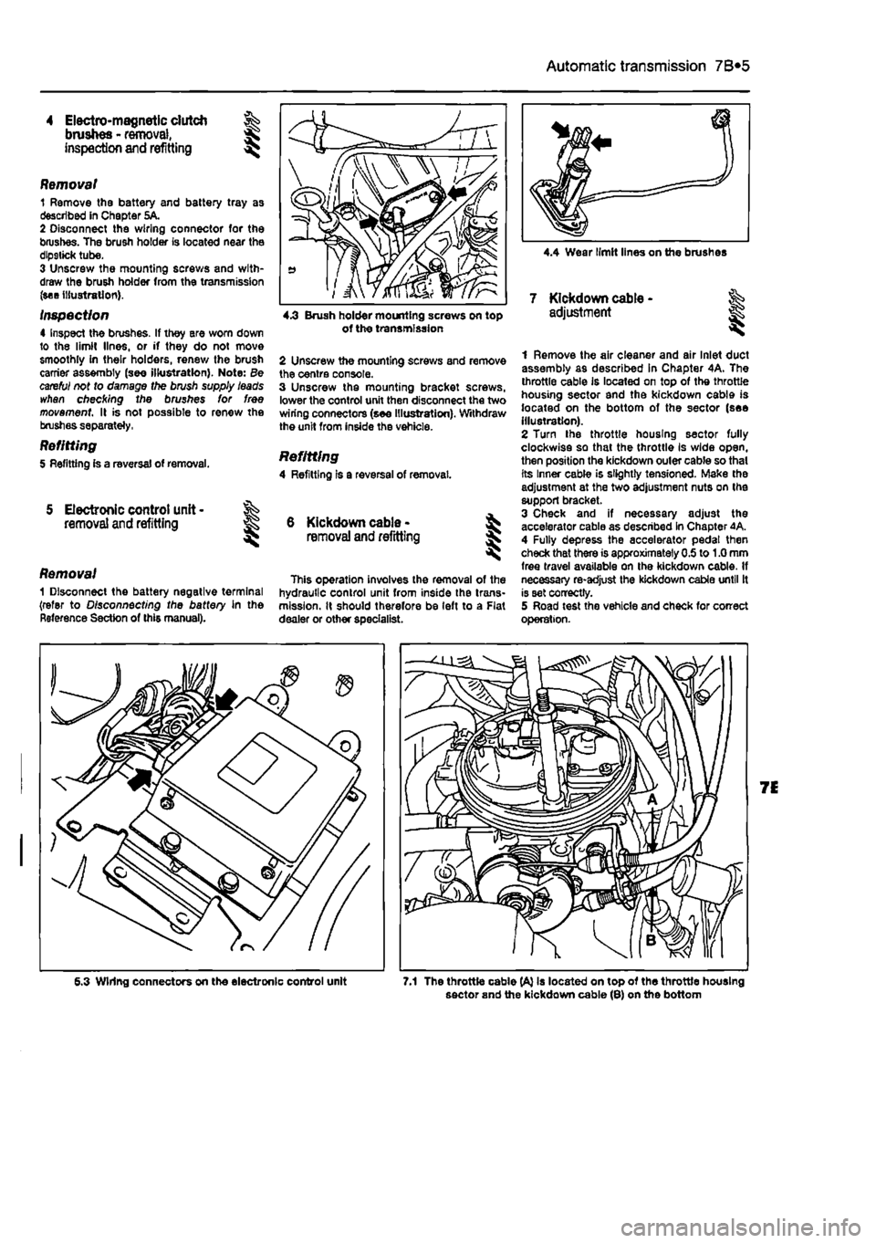
Removal 1 Remove the battery and battery tray as described in Chapter 5A. 2 Disconnect the wiring connector for the brushes. The brush holder is located near the dlp9tick tube. 3 Unscrew the mounting screws and with-draw the brush holder from the transmission (see illustration).
inspection 4 Inspect the brushes. If they ere worn down to the limit lines, or if they do not move smoothly in their holders, renew the brush carrier assembly (see illustration}. Note: Be careful not to damage the brush supply leads whan checking the brushes for free movement II is not possible to renew the brushes separately,
Refitting 5 Refitting is a reversal of removal.
5 Electronic control unit • removal and refitting
Removal 1 Disconnect the battery negative terminal (refer to Disconnecting the battery in the Reference Section of this manual).
4.3 Brush holder mounting screws on top of tho transmission
2 Unscrew the mounting screws and remove the centre console. 3 Unscrew the mounting bracket screws, lower the control unit then disconnect the two wiring connectors (see Illustration). Withdraw the unit from inside the vehicle.
Refitting 4 Refitting Is a reversal of removal.
6 Kickdown cable -removal
and
refitting I
This operation involves the removal of the hydraulic control unit from inside the trans-mission. It should therefore be left to a Flat dealer or other specialist.
1 Remove the air cleaner and air Inlet duct assembly as described in Chapter 4A. The throttle cable is located on top of the throttle housing sector and the kickdown cable is located on the bottom of the sector (see Illustration). 2 Turn the throttle housing sector fully clockwise so that the throttle Is wide open, then position the kickdown outer cable so thai its Inner cable is slightly tensioned. Make the adjustment at the two adjustment nuts on the support bracket. 3 Check and if necessary adjust the accelerator cable as described In Chapter 4A. 4 Fully depress the accelerator pedal then check that there is approximately 0.5 to 1.0 mm free travel available on the kickdown cable. If necessary re-adjust the kickdown cable until It is set correctly. 5 Road test the vehicle and check for correct operation.
6.3 Wiring connectors on tho electronic control unit 7.1 The throttle cable (A} Is located on top of the throttle housing sector and the kickdown cable (8) on the bottom
Page 173 of 225
8*2 Driveshafts
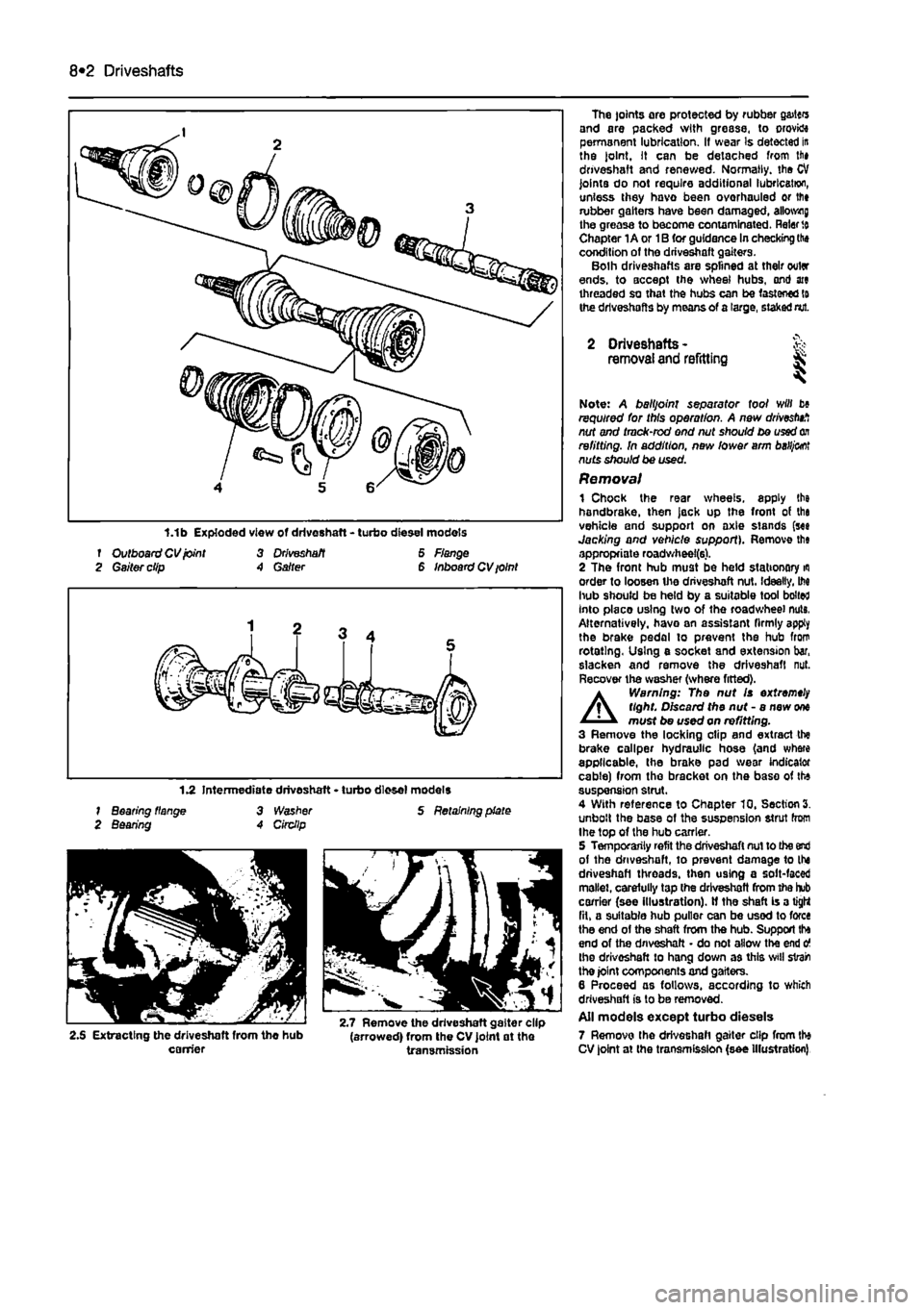
f Outboard CV joint 3 Driveshaft 6 Flange 2 Gaiter clip A Garter 6 Inboard CV ioint
1.2 Intermediate driveshaft • turbo diesel models 1 Bearing flange 3 Washer S Retaining plate 2 Bearing A Circllp
2.S Extracting the driveshaft from the hub (arrowed) from the CV joint at the carrier transmission
The joints are protected by rubber g&itcrs and are packed with grease, to orovktt permanent lubrication. If wear Is detected in the joint. It can be detached from lii» driveshaft and renewed. Normally, the CV joints do not require additional lubrication, unless they havo been overhauled or lfi» rubber gaiters have been damaged, allotting the greasa to become contaminated. Rater
to
Chapter 1A or 1B for guidance In checking the condition of the driveshaft gaiters. Bolh driveshafts are splined at their outer ends, to accept the wheel hubs, ond ate threaded so that the hubs can be fastened to the driveshafts by means of a large, staked nut.
2 Driveshafts -removal and refitting & ^
Note: A balljoint separator tool will b» required for this operation. A new drivestnf, nut and tmck-rod end nut should be used
on
refitting. In addition, new lower arm
baHj&ot
nuts should be used. Removal 1 Chock the rear wheels, apply the handbrake, then jack up the front of tha vehicle and support on axle stands (see Jacking and vehicle support). Remove th« appropriate roadwheel(6). 2 The front hub must be held stationary
m
order to loosen the driveshaft nut. Ideally, M hub should be held by a suitable tool bolted Into placo using two of the roadwheel nuts, Alternatively, havo an assistant firmly apply the brake pedal to prevent the hub from rotating. Using e socket and extension bar, slacken and remove the driveshaft nut. Recover the washer (where fitted).
A
Warning: The nut Is extremely tight. Discard the nut - a new
one
must be used on refitting. 3 Remove the locking clip and extract the brake caliper hydraulic hose (and where applicable, the brake pad wear indicator cable) from the bracket on the base of the suspension strut. 4 With reference to Chapter 10, Section 3. unbolt the base of the suspension strut from Ihe top of the hub carrier. 5 Temporarily refit the driveshaft nut to the end of the driveshaft, to prevent damage to the driveshaft threads, then using a solt-faced mallet, carefully tap the driveshaft from the hub carrier (see illustration). If the shaft is a tight fit, a suitable hub puller can be used to force the end of the shaft from the hub. Support tha end of the driveshaft • do not allow the end o the driveshaft to hang down as this svill strain the joint components and gaiters. 6 Proceed as follows, according to which driveshaft is to be removed. All models except turbo diesels 7 Remove the driveshaft gaiter clip from the CV joint at the transmission (see Illustration)
Page 178 of 225
9*2 Braking system
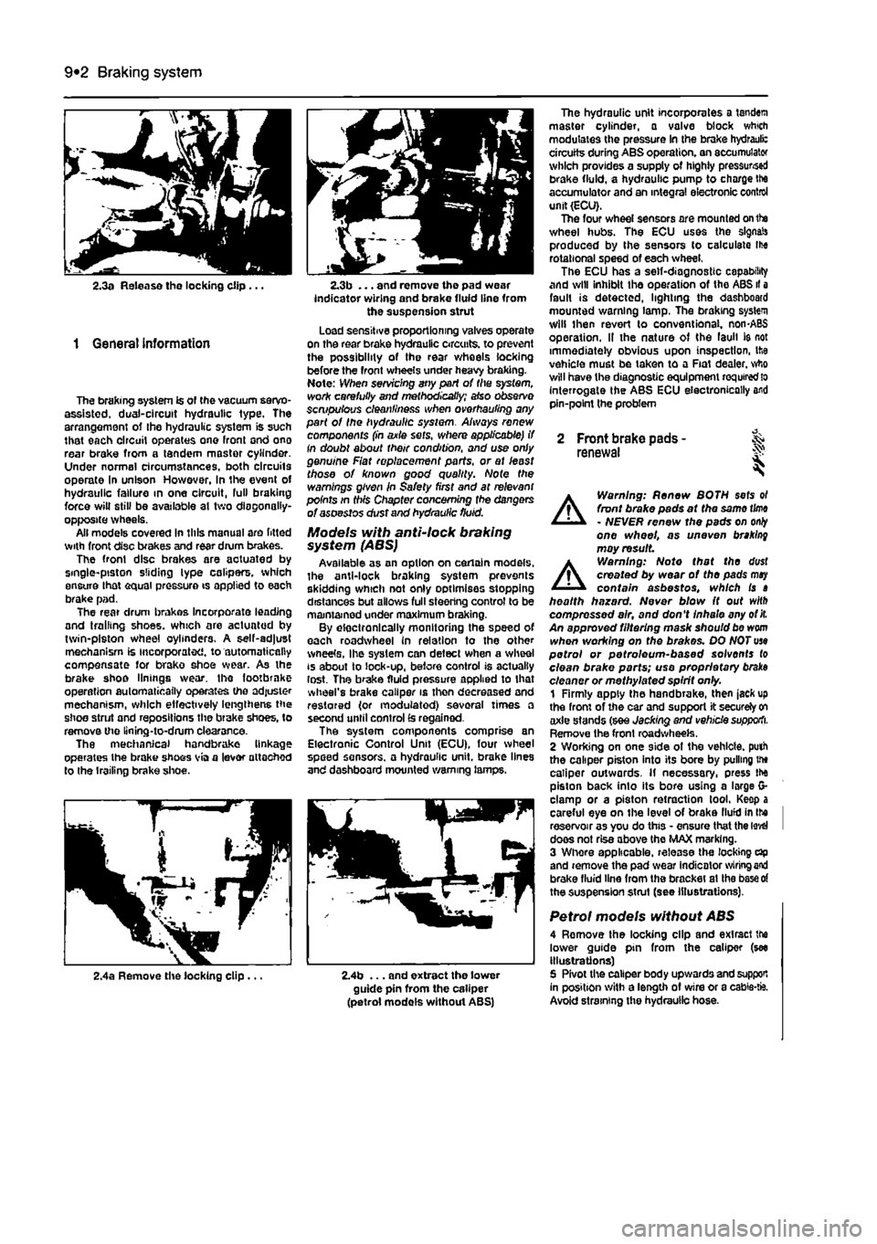
2.3a Release tho locking clip ...
1 General information
The braking system is of the vacuum servo-assisted. dual-circuit hydraulic type. The arrangement of Ihe hydraulic system is such that each circuit operates one front ond ono rear brake from a tandem master cylinder. Under normal circumstances, both circuits operate In unison However, in the event of hydraulic failure in one circuit, lull braking force will still be available at two diagonally-opposite wheels. All models covered in this manual are fitted with front disc brakes and rear drum brakes. The front disc brakes are aotuated by single-piston sliding lype calipers, which ensure lhat equal pressure is applied to each brake pad. The rear drum brakes incorporate leading and trailing shoes, which are actuated by twin-piston wheel cylinders. A self-adjust mechanism is incorporated, to automatically compensate for brako shoe wear. As the brake shoe linings wear, the footbrnke operation automatically operates the adjuster mechanism, which effectively lengthens the shoe strut and repositions the brake shoes, to remove the llning-to-drum clearance. The mechanical handbrake linkage operates the brake shoos via a lever attached to the trailing brake shoe.
2.3b ... and remove the pad wear indicator wiring and brake fluid line from the suspension strut Load sensitive proportioning valves operate on the rear brake hydraulic circuits, to prevent the possibility of the rear wheels locking before the front wheels under heavy braking. Note: When servicing any part of the system, work carefully and methodically; also observe scmpulous cleanliness when overhauling any part of the hydraulic sysiem. Always renew components (in axle sets, where applicable) if In doubt about their condition, and use only genuine Fiat replacement parts, or at least those of known good quality. Note the warnings given in Safety first and at relevant points in this Chapter concerning fhe dangers of asoestos dust and hydraulic fluid.
Models with anti-lock braking system (ABS) Available as an option on certain models, the anti-lock braking system prevents skidding which not only optimises stopping distances but allows full steering control to be maintained under maximum braking. By electronically monitoring the speed of each roadwheel in relation to the other wneete, Ihe system can detect when a wheel is about to lock-up, before control is actually lost. The brake fluid pressure applied to that wheel's brake caliper is then decreased and restored (or modulated) several times a second until control
£s
regained. The system components comprise an Electronic Control Unit (ECU), four wheel speed sensors, a hydraulic unit, brake lines and dashboard mounted warning lamps.
The hydraulic unit incorporates a tandem master cylinder, a valve block which modulates the pressure in the brake hydrauli: circuits during ABS operation, an accumulator which provides a supply of highly pressursed brake fluid, a hydraulic pump to charge Ihe accumulator and an integral electronic control unit (ECU). The four wheel sensors are mounted on the wheel hubs. The ECU uses the signals produced by the sensors to calculate Ihe rotational speed of each wheel, The ECU has a self-diagnostic capability and will inhibit the operation of the ABS il a fault is detected, lighting the dashboard mounted warning lamp. The braking system will then revert lo conventional. non-ABS operation. II the nature of the laull ie not immediately obvious upon inspection, the vehicle must be taken to a Fiat dealer, who will have the diagnostic equipment
required
lo interrogate the ABS ECU electronically and pin-point the problem
2 Front brake pads - & renewal S
A
Warning: Renew BOTH sets ol front brake pads at the same
time
- NEVER renew the pads on
only
one wheel, as uneven braking may result
A
Warning: Note that the dust created by wear of the pads
may
contain asbestos, which is a health hazard. Never blow It out with compressed air, and don't inhale any of
it.
An approved filtering mask should be worn when working on the brakes. DO NOT use petrol or petroleum-based solvents to clean brake parts; use proprietary braks cleaner or methylated spirit only. 1 Firmly apply the handbrake, then jack up the front of the car and support it securely
on
axle stands (see Jacking and vehicle supporti. Remove the front roadwheeis. 2 Wording on one side of the vehicle, puth the caliper piston into its bore by pulling the caliper outwards. If necessary, press the piston back into its bore using a large G-clamp or a piston retraction tool. Keep a careful eye on the level of brake llufd in Ihe I reservoir as you do this - ensure that the
level
I does not rise above the MAX marking. 3 Whore applicable, release the locking dp and remove the pad wear indicator
wiring end
brake fluid line from the bracket at Ihe
base of
the suspension strut (see illustrations).
Petrol models without ABS 4 Remove the locking clip and exlracl the lower guide pin from the caliper (see illustrations) 5 Pivot the caliper body upwards and support In position with a length of wire or a cabie-fc. Avoid straining the hydraulic hose.
2,4a Remove the locking clip ... 2.4b ... and extract the lower guide pin from the caliper (petrol models without ABS)
Page 179 of 225
Braking system 9®3
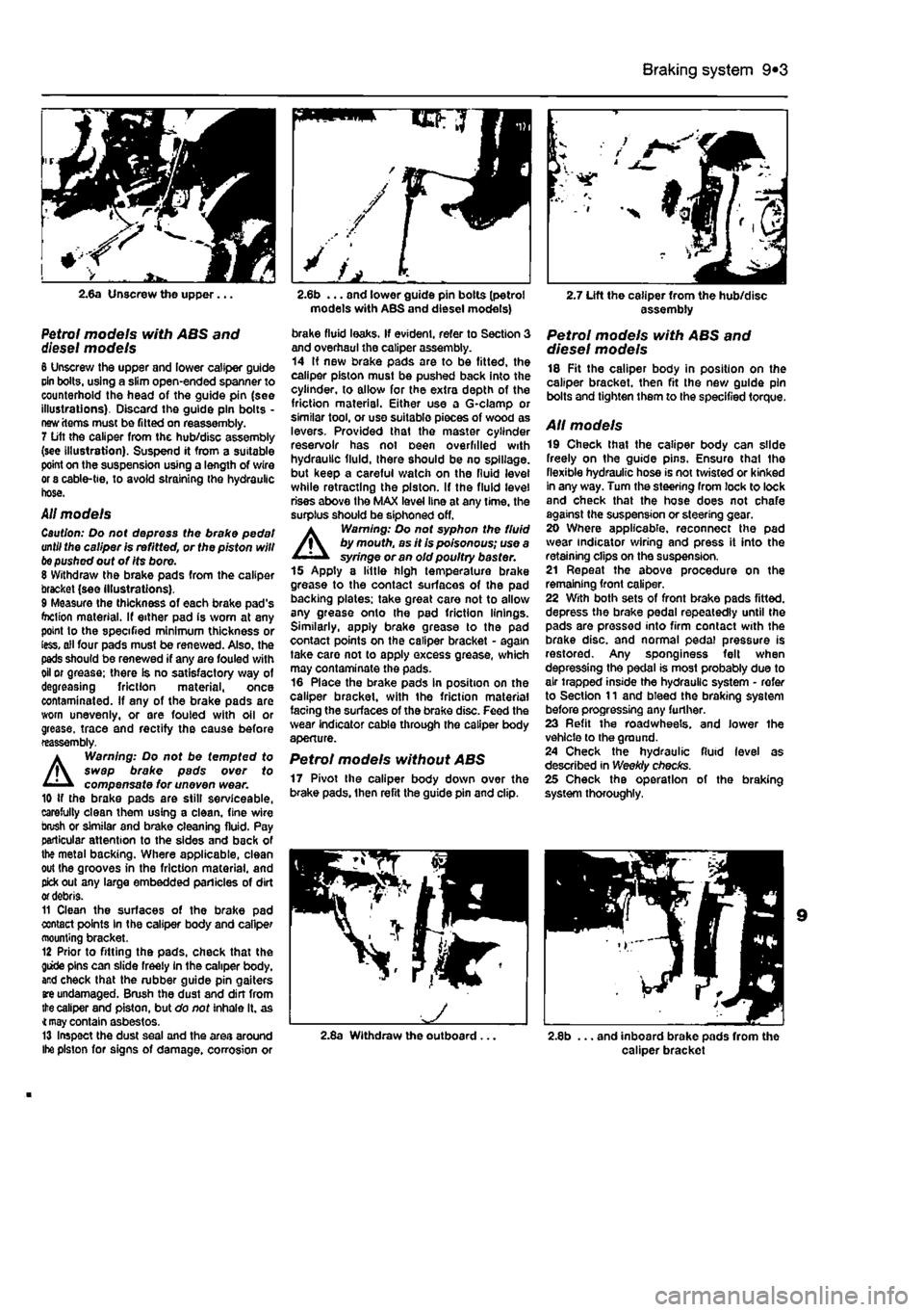
2.6a Unscrew the upper...
Petrol models with ABS and diesel models 6 Unscrew the upper and lower caliper guide cin bolts, using a slim open-ended spanner to counterhold the head of the guide pin (see illustrations). Discard the guide pin bolts -new items must be fitted on reassembly. 7 Lift the caliper from the hub/disc assembly (see illustration). Suspend it from a suitable point on the suspension using a length of wire or 8 cable-tie, to avoid straining the hydraulic hose.
All models Caution: Do not depress the brake pedal until the caliper is refitted, or the piston will
be
pushed out of Its bore. 8 Withdraw the brake pads from the caliper bracket (see illustrations). 9 Measure the thickness of each brake pad's foclion material. If either pad is worn at any point to the specified minimum thickness or less, all four pads must be renewed. Also, the pads should be renewed if any are fouled with oil or grease; there is no satisfactory way of degreasing friction material, once contaminated. If any of the brake pads are worn unevenly, or are fouled with oil or grease, trace and rectify the cause before reassembly.
A
Warning: Do not be tempted to swap brake pads over to compensate for uneven wear. 10 if the brake pads are still serviceable, carefully clean them using a clean, fine wire brush or similar and brake cleaning fluid. Pay particular attention to the sides and back of the metal backing. Where applicable, clean out the grooves in the friction material, and pick out any large embedded panicles of dirt
or
debris. 11 Clean the surfaces of the brake pad contact points In the caliper body and caliper mounting bracket. 12 Prior to fitting the pads, check that the giide pins can slide freely in the caliper body, and check that the rubber guide pin gaiters
are
undamaged. Brush the dust and din from
the
caliper and piston, but do not inhale it. as
4 may
contain asbestos. 13 Inspect the dust seal and the area around Ihe piston for signs of damage, corrosion or
models with ABS and diesel models)
brake fluid leaks. If evident, refer to Section 3 and overhaul the caliper assembly. 14 If new brake pads are to be fitted, the caliper piston must be pushed back into the cylinder, to allow for the extra depth of the friction material. Either use a G-clamp or similar tool, or use suitable pieces of wood as levers. Provided that the master cylinder reservoir has not oeen overfilled with hydraulic fluid, there should be no spillage, but keep a careful watch on the fluid level while retracting the piston. If the fluid level rises above the MAX level line at any time, the surplus should be siphoned off. A Warning: Do not syphon the fluid by mouth, as it is poisonous; use a syringe or an old poultry baster. 15 Apply a little high temperature brake grease to the contact surfaces of the pad backing plates: take great care not to allow any grease onto the pad friction linings. Similarly, apply brake grease to the pad contact points on the caliper bracket - again take care not to apply excess grease, which may contaminate the pads. 16 Place the brake pads in position on the caliper bracket, with the friction material facing the surfaces of the brake disc. Feed the wear indicator cable through the caliper body aperture.
Petrol models without ABS 17 Pivot the caliper body down over the brake pads, then refit the guide pin and clip.
2.7 Lift the caliper from the hub/disc assembly
Petrol models with ABS and diesel models 18 Fit the caliper body in position on the caliper bracket, then fit the new guide pin bolts and tighten them to the specified torque.
AH models 19 Check that the caliper body can slide freely on the guide pins. Ensure that the flexible hydraulic hose is not twisted or kinked In any way. Turn the steering from lock to lock and check that the hose does not chafe against the suspension or steering gear. 20 Where applicable, reconnect the pad wear indicator wiring and press it into the retaining clips on the suspension. 21 Repeat the above procedure on the remaining front caliper. 22 With both sets of front brake pads fitted, depress the brake pedal repeatedly until the pads are pressed into firm contact with the brake disc, and normal pedal pressure is restored. Any sponginess felt when depressing the pedal is most probably due to air trapped inside the hydraulic system - refer to Section 11 and bleed the braking system before progressing any further. 23 Refit the roadwheels. and lower the vehicle to the ground. 24 Check the hydraulic fluid level as described in Weekly checks. 25 Check the operation of the braking system thoroughly,
2.8a Withdraw the outboard... 2.8b ... and inboard brake pads from the caliper bracket
Page 180 of 225
9*4 Braking system
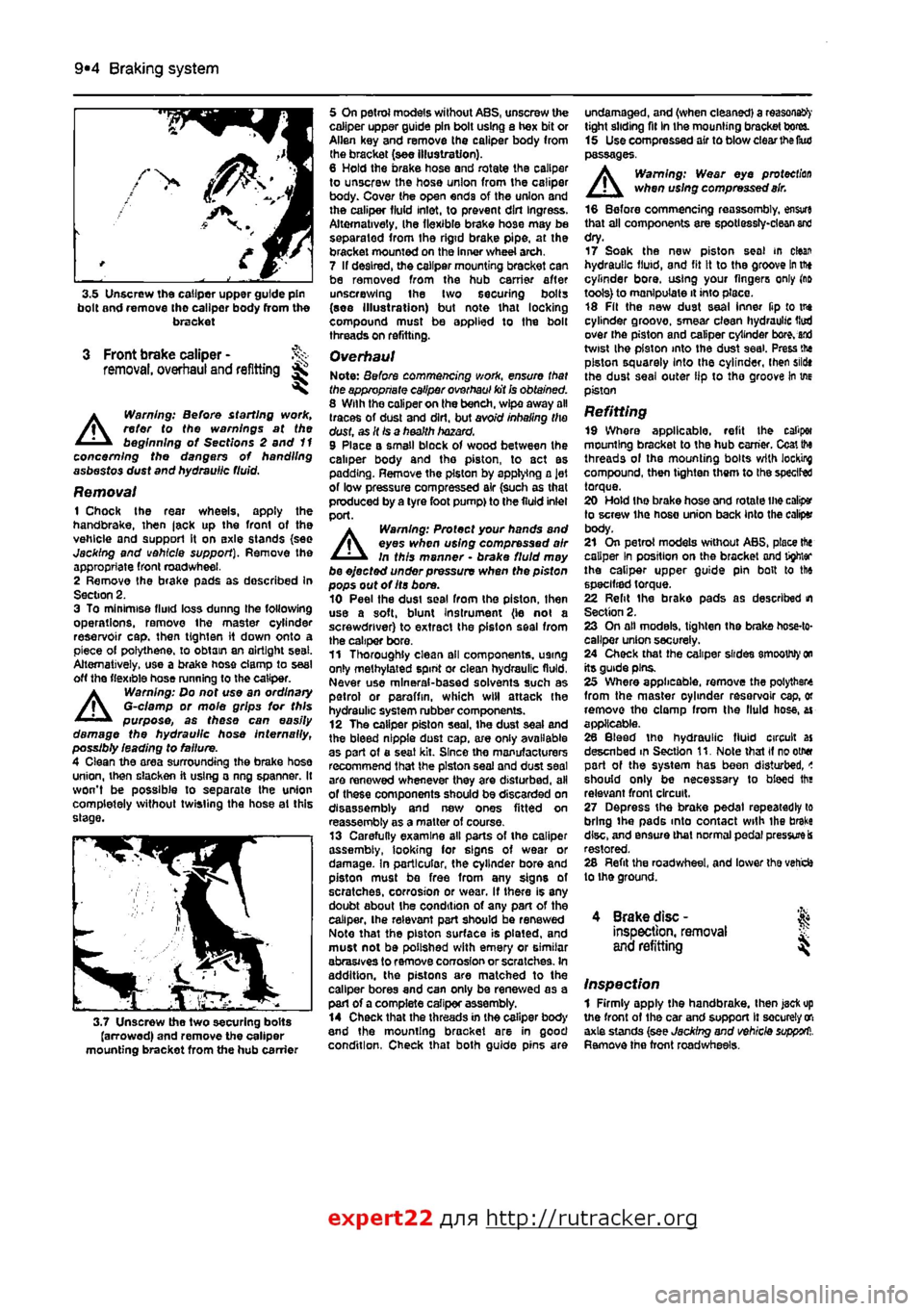
3.5 Unscrew the caliper upper guide pin bolt and remove tho caliper body (torn the bracket
3 Front brake caliper -removal, overhaul and refitting ^
A
Warning: Before starting work, refer to the warnings at the beginning of Sections 2 and 11 concerning the dangers of handling asbestos dust and hydraulic fluid.
Removal 1 Chock the rear wheels, apply the handbrake, then |ack up the front of the vehicle and support it on axle stands {see Jacking and vehicle support). Remove the appropriate front roadwheel. 2 Remove the brake pads as described In Section 2. 3 To minimise fluid loss dunng the following operations, remove the master cylinder reservoir cap. then
tig hi en
it down onto a piece of polythene, to obtain an airtight seat. Alternatively, use a brake hose clamp to seal off the flexible hose running to the caliper.
A
Warning: Do not use an ordinary G-clamp or mole grips for this purpose, as these can easily damage the hydraulic hose Internally, possibly leading to failure. 4 Clean the area surrounding the brake hose union, then slacken ft using a ring spanner. It won't be possible to separate the union completely without twisting the hose ai this slage.
3.7 Unscrew the two securing bolts (arrowed) and remove the caliper mounting bracket from the hub carrier
5 On petrol models without ABS, unscrew the caliper upper guide pin bolt using a hex bit or Allen key and remove the caliper body from the bracket (see illustration). 6 Hold the brake hose and rotate the caliper to unscrew the hose union from the caliper body. Cover the open ends of the union and the caliper fluid inlet, to prevent dirt Ingress. Alternatively, Ihe flexible brake hose may be separated from the rigid brake pipe, at the bracket mounted on the Inner wheel arch. 7 If desired, the caliper mounting bracket can be removed from the hub carrier after unscrewing ihe two securing bolts (see Illustration) but note that locking compound must be applied to the bolt threads on refitting.
Overhaul Note: Before commencing work, ensure that the appropriate caliper overhaul kit
Ss
obtained. 8 With the caliper on the bench, wipe away all (races of dust and dirt, but avoid inhaling the dust, as It
Is
a health hazard. 9 Place a small block of wood between the caliper body and tho piston, to act as padding. Remove the piston by applying a Jet of low pressure compressed air (such as that pioduced by a tyre foot pump) to the fluid inlel port.
A
Warning: Protect your hands and eyes when using compressed air In this manner • brake fluid moy be ejected under pressure when the pisfon pops out of Its bore. 10 Peel the dusi seal from the piston, then use a soft, blunt instrument (ie not a screwdriver) to extract the piston seal from the caliper bore. 11 Thoroughly clean all components, U9tng only methylated spint or clean hydraulic fluid, Never use mineral-based solvents such as petrol or paraffin, which will attack Ihe hydraulic system rubber components. 12 The caliper piston seal, the dust seal and the bleed nipple dust cap, a/e oniy available as part of a seat kit. Since the manufacturers recommend that the piston seal and dust seal are renewed whenever they are disturbed, all of these components should be discarded on disassembly and new ones fitted on reassembly as a matter of course. 13 Carefully examine all parts of the caliper assembly, looking for signs of wear or damage. In particular, the cylinder bore and piston must be free from any signs of scratches, corrosion or wear. If there is any doubt about ihe condition of any part of the caliper, the relevant port should be renewed Note that the piston surface is plated, and must not be polished with emery or similar abrasives to remove corrosion or scratches. In addition, the pistons are matched to the caliper bores and can only be renewed as a part of a complete caliper assembly. 14 Check that the threads in the caliper body and the mounting bracket are in good condition, Check that both guide pins are
undamaged, and (when cleaned) a reasons^' tight sliding fit In the mounting bracket bores. 15 UsecompressedairtOblow clear the IkuJ passages. Warning: Wear eye protection when using compressed
air.
16 Before commencing reassembly, en$vr« that all components are spotlessly-clean
and
dry. 17 Soak the new piston seal m clean hydraulic fluid, and fit it to the groove
In
tftt cylinder bore, using your fingers only (rift tools) to manipulate it into place. 18 Fit the new dust seal inner ftp to tne cylinder groove, smear clean hydraulic Hud over the piston and caliper cylinder
bore, and
twist ihe pfaton into the dust seal. Press tne piston squarely Into the cylinder, then sildt the dust seal outer lip to tho groove in we piston
Refitting 19 Where applicable, refit the caliper mounting bracket to thB hub earner. Ccaitto threads ol the mounting bolts with locking compound, then tighten them to the speclfed torque. 20 Hold the brake hose and rotate Ihe calip* to screw the hose union back Into the caliper body. 21 On petrol models without ABS, place the caliper In position on the bracket and tighter the caliper upper guide pin bolt to the specified torque. 22 Relit ihe brake pads as described m Section 2. 23 On all models, tighten the brake hose-to-callper union securely. 24 Check that the caliper slides smoothly
on
its guide pins. 25 Where applicable, remove the polytbste from the master oyhnder rasarvoir cap, or remove tho clomp from the fluid hose, ai applicable. 26 Bleed tho hydraulic fluid circuit as desenbed m Section 11. Note that if rootMf part of the system has been disturbed, < should only be necessary to bleed tha relevant front circuit, 27 Depress the brake pedal repeatedly to bring ihe pads into contact with ihe brake disc, and ensure that normal pedal
pressure is
restored. 28 Refit the roadwheel, and lower tha veti'cfc lo ihe ground.
4 Brake disc -
inspection,
removal
and
refitting
Inspection 1 Firmly apply the handbrake, then jaefcup the front of the car and support It securely
oft
axle stands (see Jacking and vehicle
support1,.
Remove the front roadwhesls.
expert22 f
a http://rutracker.org
Page 181 of 225
Braking system 9®5
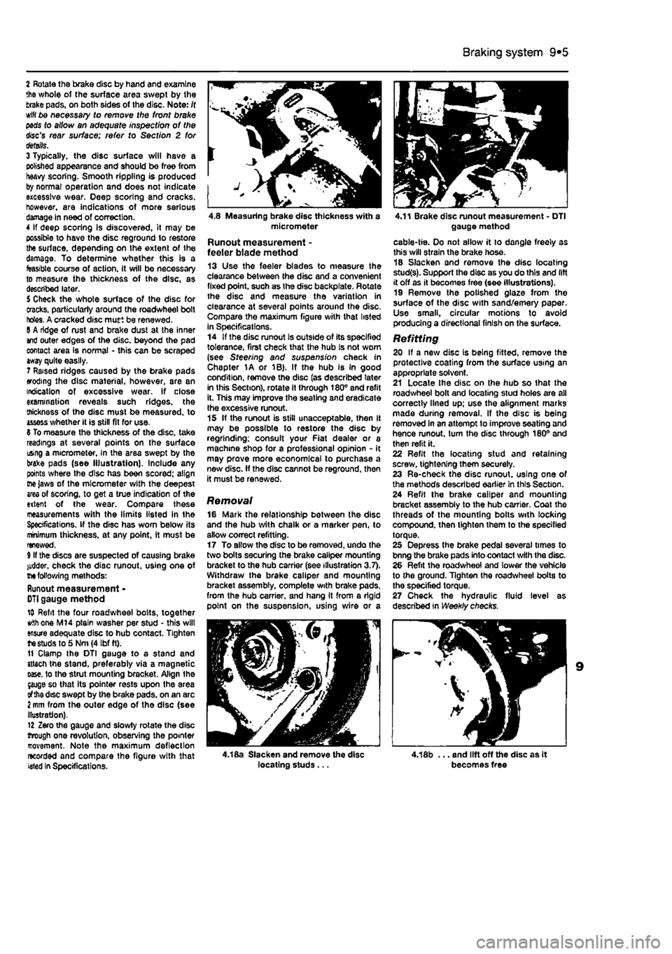
2 Rotate the brake disc by hand and examine the whole of the surface area swept by the brake pads, on both sides ot the disc. Note: /( will bo necessary to remove the front brake pads to allow an adequate inspection of the disc's rear surface; refer to Section 2 tor details. 3 Typically, the disc surface will have a polished appearance and should be free from heavy scoring. Smooth rippling is produced by normal operation and does not indicate excessive wear. Deep scoring and cracks, however, are indications of more serious damage in need of correction. 4 If deep scoring Is discovered, it may be possible to have the disc reground to restore the surface, depending on the extent of the damage. To determine whether this is a feasible course of action, it will be necessary to measure the thickness of the disc, as described later. 5 Check the whole surface of the disc for cracks, particularly around the roadwheel bolt holes. A cracked disc mutt be renewed. 6 A ridge of rust and brake dust at the inner and outer edges of the disc, beyond the pad contact area is normal - this can be scraped tway quite easily. 7 Raised ridges caused by the brake pads eroding the disc material, however, are an indication of excessive wear. If close examination reveals such ridges, the oiicknoss of the disc must be measured, to usess whether it is still fit for use. 8 To measure the thickness of the disc, take readings at several points on the surface using a micrometer. In the area swept by the brake pads (see Illustration). Include any points where the disc has been scored: align me Jaws of the micrometer with the deepest ares of scoring, to get a true indication of the extent of the wear. Compare these ineasurements with the limits listed in the Specifications. If the disc has worn below its minimum thickness, at any point, it must be renewed. 9 If the discs are suspected of causing brake luddor, check the disc runout, using one of
me
following methods: Runout measurement -
DTI
gauge method 10 Refit the four roadwheel bolts, together
w.1h
one M14 plain washer per stud • this will ensure adequate disc to hub contact. Tighten te studs to 5 Nm (4 Ibf ft). 11 Clamp the DTI gauge to a stand and attach the stand, preferably via a magnetic oase. to the strut mounting bracket. Align the jauge so that its pointer rests upon the area of the dtsc swept by the brake pads, on an arc i mm from the outer edge of tho disc (soe illustration). 12 Zero the gauge and slowly rotate the disc trough one revolution, observing tho pointer rcovement. Note the maximum deflection recorded and compare the figure with that >«ted In Specifications.
4.8 Measuring brake disc thickness with a micrometer
Runout measurement -feeler blade method 13 Use the feeler blades to measure the clearance between the disc and a convenient fixed point, such as the disc backplate. Rotate the disc and measure the variation in clearance at several points around the disc, Compare the maximum figure with that listed in Specifications. 14 If the disc runout Is outside of its specified tolerance, first check that the hub Is not worn (see Steering and suspension check in Chapter 1A or 1B). If the hub is In good condition, remove the disc (as described later in this Section), rotate it through 180° and refit it. This may improve the seating and eradicate Ihe excessive runout. 15 If the runout is still unacceptable, then It may be possible to restore the disc by regrinding; consult your Fiat dealer or a machine shop for a professional opinion - it may prove more economical to purchase a new disc. If the disc cannot be reground, then it must be renewed.
Removal 16 Mark the relationship between the disc and the hub with chalk or a marker pen, to allow correct refitting. 17 To allow the disc to be removed, undo the two bolts securing (he brake caliper mounting bracket to the hub carrier (see illustration 3.7). Withdraw the brake caliper and mounting bracket assembly, complete with brake pads, from the hub carrier, and hang it from a rigid point on the suspension, using v/lre or a
4.18a Slacken and remove the disc locating studs ...
4.11 Brake disc runout measurement - DTI gauge method
cable-tie. Oo not allow it to dangle freely as this will strain the brake hose. 18 Slacken and remove the disc locating stud(s). Support the disc as you do this and lift it off as it becomes free (see illustrations). 19 Remove the polished glaze from the surface of the disc with sand/emery paper. Use small, circular motions to avoid producing a directional finish on the surface.
Refitting 20 If a new disc Is being fitted, remove the protective coating from the surface U9ing an appropriate solvent. 21 Locate Ihe disc on ihe hub so that the roadwheel bolt and locating stud holes are all correctly lined up; use the alignment marks made during removal. If the disc is being removed in an attempt to improve seating and hence runout, turn the disc through 180° and then refit it. 22 Refit the locating stud and retaining screw, tightening them securely. 23 Re-check the disc runout, using one of the methods described earlier in this Section. 24 Refil the brake caliper and mounting bracket assembly to the hub carrier. Coat the threads of the mounting bolts with locking compound, then tighten them to the specified torque. 25 Depress the brake pedal several times to bnng the brake pads into contact with the disc. 26 Refit the roadwheel and lower the vehicle to the ground. Tighten the roadwheel bolts to the specified torque. 27 Check the hydraulic fluid level as described in Weekly checks.
4,18b ... and lift off the disc as It becomes free
Page 182 of 225
9*6 Braking system
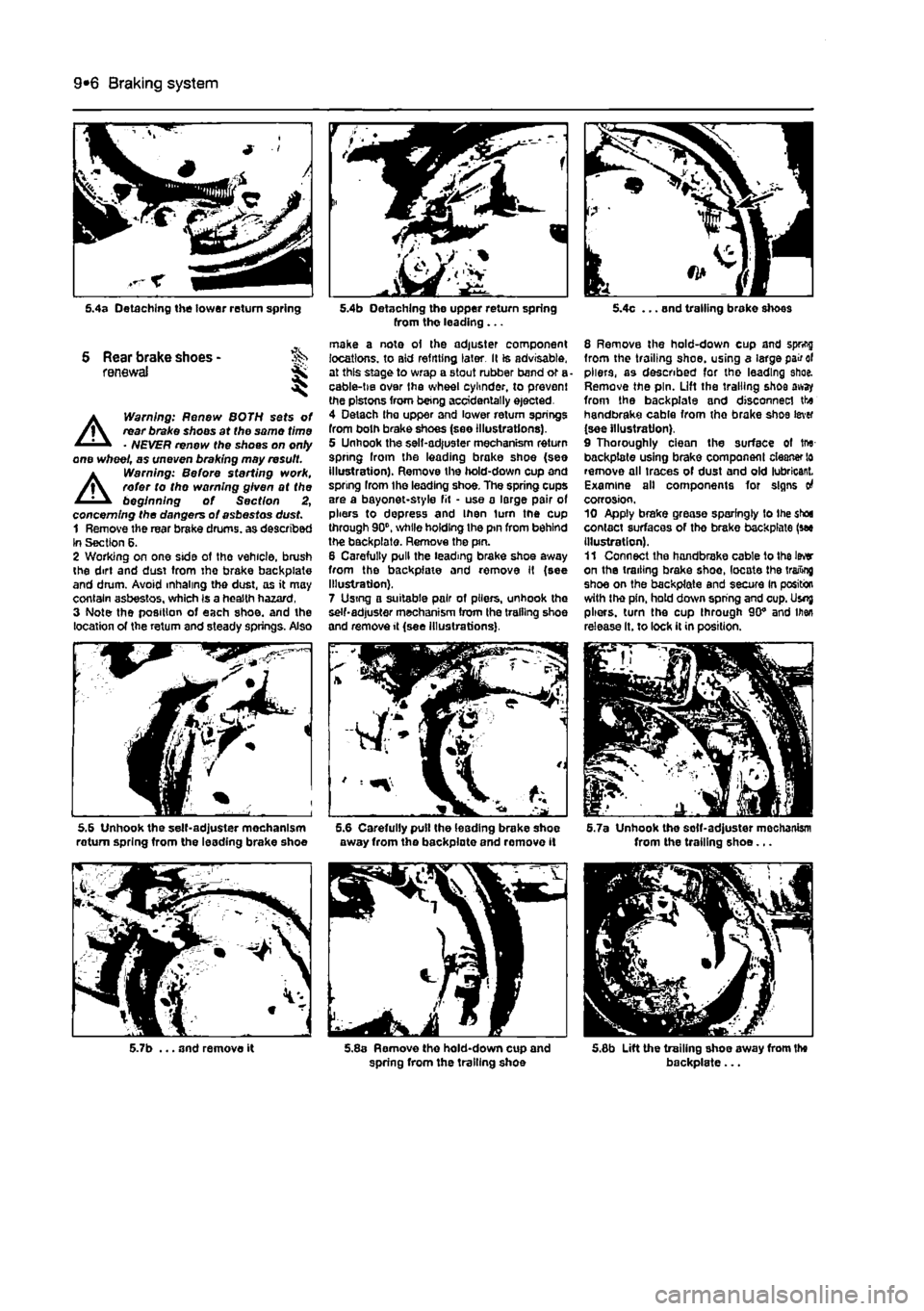
5.4a Detaching the tower return spring
S Rear brake shoes -renewal ji,
A
Warning: Renew BOTH sets of rear brake shoos at the same time • NEVER renew the shoes on onty one wheel, as uneven braking may result.
A
Warning: Before sterling work, refer to tho warning given at the beginning of Section 2, concerning the dangers of asbestos dust. 1 Remove the rear brake drums, as described In Section 6. 2 Working on one side ot the vehicle, brush the dirt and dust tram tho brake backpiate and drum. Avoid inhaling the dust, as it may contain asbestos, which Is a health hazard, 3 Note the position of each shoe, and the location of the return and steady springs. Also
5.6 Unhook the self-adjuster mechanism roturn spring from the leading brake shoe
5.7b ... and remove it
5.4b Detaching the upper return spring from tho leading ...
make a note oi the adjuster component locations, to aid refitting later. Il is advisable, at this stage to wrap a stout rubber band or a cable-tie over Ihe wheel cylinder, to prevent the pistons from being accidentally ejected. 4 Detach tha upper and lower return springs from both brake shoes (see illustrations). 5 Unhook the sell-adjuster mechanism return spring Iroin the leading brake shoe (see illustration). Remove the hold-down cup and spring from the leading shoe. The spring cups are a bayonet-style fit • use a large pair of pliers to depress and Ihen turn the cup through 90", while holding Ihe pin from behind the backpiate. Remove the pin. 6 Carefully pull the leading brake shoe away from the backpfaie and remove It (see Illustration). 7 Using a suitable pair of pliers, unhook the self-adjuster mechanism from the trailing shoe and remove it (see Illustrations).
away from the backpiate and remove it
5.8a Remove the hold-down cup and spring from the trailing shoe
5.4c ... and trailing brake shoes
8 Remove the hold-down cup and spring from the trailing shoe, using a large pair of pliers, as described for the leading shoe. Remove the pin. Lift the trailing shoe away from the backpiate and disconnect the handbrake cable from the brake shoe lever (see illustration). 9 Thoroughly ciean the surface of tru-backpiate using brake component cleaner lo remove all traces of dust and old lubricant. Examine all components for signs o4 corrosion. 10 Apply brake grease sparingly to the shoe contact surfaces of tho brake backpiate (see Illustration). 11 Connect tha handbrake cable to the Iwr on the trailing brake shoe, locate the trailing shoe on the backpiate and secure In position with the pin, hold down spring and cup. Usnj pliers, turn the cup through 90" and men release It. to lock it in position.
5.7a Unhook the solf-adjuster mochanism from the trailing shoe...
5.6b Lift the trailing shoe away from the backpiate...
Page 185 of 225
Braking system 9®9
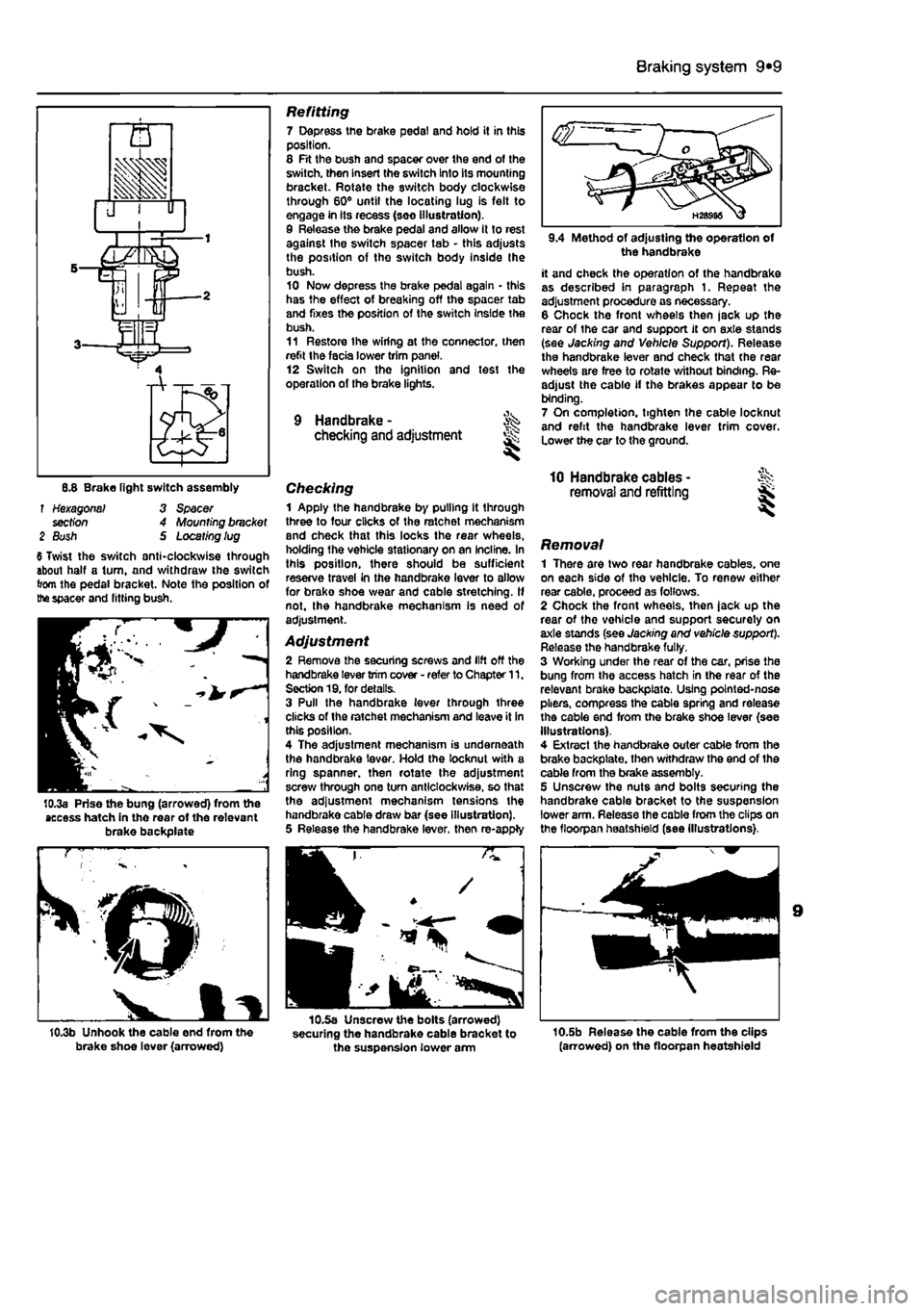
6.8 Brake light switch assembly f Hexagonal' 3 Spacer section 4 Mounting bracket 2 Bush S Locating lug 6 Twist the switch anti-clockwise through about half a turn, and withdraw the switch from the pedal bracket. Note the position of the spacer and fitting bush.
10.3a Prise the bung (arrowed) from the access hatch in the rear of the relevant brake backplate
10.3b Unhook the cable end from the brake shoe lever (arrowed)
Refitting 7 Depress the brake pedal and hold it in this position. 8 Fit the bush and spacer over the end of the switch, then Insert the switch Into its mounting bracket. Rotate the switch body clockwise through 60° until the locating lug is felt to engage in its recess (seo illustration). 9 Release the brake pedal and allow It to rest against the switch spacer tab - this adjusts the position of the switch body Inside Ihe bush. 10 Now depress the brake pedal again - this has the effect of breaking off the spacer tab and fixes the position of the switch Inside the bush. 11 Restore Ihe wiring at the connector, then refit the facia lower trim panel. 12 Switch on the ignition and test the operation of the brake lights.
9 Handbrake - ^ checking and adjustment
Checking 1 Apply the handbrake by pulling it through three to four clicks of the ratchet mechanism and check that this locks the rear wheels, holding the vehicle stationary on an incline. In this position, there should be sufficient reserve travel in the handbrake lever to allow for brako shoe wear and cable stretching. If not. Ihe handbrake mechanism Is need of adjustment.
Adjustment 2 Remove the securing screws and lift off the handbrake lever trim cover - refer to Chapter 11. Section 19. for details. 3 Pull the handbrake lever through three clicks of the ratchet mechanism and leave it in this position. 4 The adjustment mechanism is underneath the handbrake lever. Hold the locknut with a ring spanner, then rotate the adjustment screw through one turn anticlockwise, so that the adjustment mechanism tensions the handbrake cable draw bar (see illustration). 5 Release the handbrake lever, then re-apply
10.5a Unscrew the bolts (arrowed) securing the handbrake cable bracket to the suspension lower arm
the handbrake it and check the operation of the handbrake as described in paragraph 1. Repeat the adjustment procedure as necessary. 6 Chock the front wheels then |ack up the rear of the car and support it on axle stands (see Jacking and Vehicle Support). Release the handbrake lever and check that the rear wheels are free to rotate v/ithout binding. Re-adjust the cable if the brakes appear to be binding. 7 On completion, tighten the cable locknut and refit the handbrake lever trim cover. Lower the car to the ground.
10 Handbrake cables -removal and refitting
Removal 1 There are two rear handbrake cables, one on each side of the vehicle. To renew either rear cable, proceed as follows. 2 Chock the front wheels, then jack up the rear of tho vehicle and support securely on axle stands (see Jacking and vehicle support). Release the handbrake fully, 3 Working under the rear of the car, prise the bung from the access hatch in the rear of the relevant brake backplato, Using pointed-nose pliers, compress the cable spring and release the cable end from the brake shoe lever (see Illustrations). 4 Extract the handbrake outer cable from the brake backplate. then withdraw the end of the cable from the brake assembly. 5 Unscrew the nuts and bolts securing the handbrake cable bracket to the suspension lower arm. Release the cable from the clips on the floorpan heatshield (see Illustrations).
10.5b Release the cable from the clips (arrowed) on the floorpsn heatshield