Pipes FIAT PUNTO 1998 176 / 1.G User Guide
[x] Cancel search | Manufacturer: FIAT, Model Year: 1998, Model line: PUNTO, Model: FIAT PUNTO 1998 176 / 1.GPages: 225, PDF Size: 18.54 MB
Page 140 of 225
Fuel system - diesel models
4C*3
7.4 Unscrew the access screw from the 7.5 Dial gauge and adapter (Bosch) rear of the Injection pump (Bosch)
7 Injection timing ^ (Bosch fuel injection pump) -checking and adjustment ^
Caution: Some of the Injection pump uttlngs and access plugs may be sealed ty the manufacturers at the factory, using
paint
or locking wire and lead seals. Do not
disturb
the seals If the vehicle is still within the warranty period, otherwise the warranty will be invalidated. Also do not attempt the timing procedure unless
accurate
Instrumentation Is available. Note: To check the injection pump timing a special
timing
probe and mounting bracket is required. Without access to this piece of
tquipment.
injection pump timing should be intrusted to a Fiat dealer or other suitably
eqwpped
specialist. 1
H
the Injection timing is being checked with ffie pump in position on the engine, rather rian as part ot the pump refitting procedure, disconnect the battery negative terminal (refer to
Disconnecting
the battery in the Reference S«ction of this manual), and remove the air rtel ducting from the front of the engine. 2 Unscrew the union nuts and disconnect the injector pipes from the Injection pump and injectors. Counterhold the unions on the pump, while unscrewing the pipe-to-pump irion
nuts.
Remove the pipes as a set. Cover open unions to keep dirt out, using small plastic bags, or fingers cut from discarded
ibut clean!)
rubber gloves. 3 Referring to Chapter 2C, set the engine at
TDC on
cylinder No 1. 4 Unscrew the access screw, situated In the centre of the four injector pipe unions, from the rear of the Injection pump (see illustration). As the screw Is removed, position a suitable container beneath the
pump
to catch any escaping fuel, Mop up any tpilt fuel with a clean cloth. 5 Screw the adapter into the rear of the pump
and
mount the dial gauge in ihe adapter (see •ustration). If access to the special Fiat *Japter cannot be gained, they can be purchased from most good motor factors. Position the dial gauge so that its plunger is at
Ifce
mid-point of its travel and securely tighten Ite adapter locknut. 6 Slowly rotate the crankshaft first back then towards whilst observing the dial gauge, to ctotermlne when the Injection pump piston is
a',
the bottom of Its travel (BDC), When the pston Is correctly positioned, zero the dial
7 Rotate the crankshaft slowly in the correct direction until the TDC timing marks are tfjned on both the crankshaft, camshaft and rjecbon pump sprockets.
6
The reading obtained on the dial gauge should be equal to the specified pump timing measurement given in the Specifications at ew start of this Chapter, If adjustment is necessary, slacken the fronl and rear pump mounting nuts/bolts and slowly rotate the
pump body until the point is found where the specified reading Is obtained. When the pump is correctly posilioned, tighten both its front and rear mounting nuts and bolts securely. 9 Rotate the crankshaft through one and three quarter rotations in the normal direction of rotation. Find the injection pump piston BDC as described in paragraph 6 and zero the dial gauge. 10 Rotate the crankshaft slowly in the correct direction of rotation until the TDC marks are aligned. Recheck the timing measurement. 11 If adjustment is necessary, slacken the pump mounting nuts and bolts and repeat the operations In paragraphs 8 to 10. 12 When the pump timing Is correctly set, unscrew the adapter and remove the dial gauge. 13 Refit the screw and sealing washer to the pump and tighten it securely. 14 If the procedure is being carried out as part of the pump refitting sequence, proceed as described in Section 5, 15 If the procedure is being carried out with the pump fitted to the engine, refit the injector pipes tightening their union nuts to the specified torque setting. Reconnect the battery and refit the air inlet ducting. 16 Start the engine, and check for any leakage at the luel unions. To enable the engine to start it may be necessary to loosen the injector union nuts while turning tho engine on the starter motor in order to purge trapped air. 17 Check and if necessary adjust the idle speed as described in Chapter 1B.
8.4 Removing the injection pump timing inspection plug (Lucas)
8 injection timing ^ (Lucas fuel injection pump) - ^ checking
and
adjustment ^
Caution: Some of the injection pump settings and access plugs may be sealed by the manufacturers at the factory, using paint or locking wire and lead seo/s. Do not disturb the seals if the vehicle Is still within the warranty period, otherwise tho warranty will be Invalidated. Also do not affempf the timing procedure unless accurate instrumentation is available.
Note: To check the Injection pump timing a speciai timing probe and mounting bracket Is required. Without access to this piece of equipment, injection pump timing should be entrusted to a Fiat dealer or other suitably equipped specialist. 1 If the injection timing is being checked with the pump tn position on the engine, rather than as part of the pump refitting procedure, disconnect the battery negative terminal (refer to Disconnecting the battery in the Reference Section of this manual), and remove the air inlet ducting from the front of the engine. 2 Unscrew the union nuts and disconnect the injector pipes from the Injection pump and In-jectors. Counterhold the unions on the pump, while unscrewing the pipe-to-pump union nuts. Remove the pipes as a set. Cover open unions to keep dirt out. using smalt plastic bags, or fingers cut from discarded (but clean!) rubber gloves. 3 Referring to Chapter 2C, set the engine at TDC on cylinder No 1, then turn the crank-shaft backwards (anti-clockwise) approx-imately a quarter of a turn. 4 Unscrew the access plug from the guide on the top of the pump body and recover the sealing washer (soe Illustration). Insert the special liming probe Into the guide, making sure it Ib correctly seated against the guide seating washer surface. Note: The timing probe must be seated against the guide sealing washer surface and not the upper lip of the guide for the measurement to be accurate. 5 Mount the bracket on the pump guide (using adapter tool) and securely mount the dial gauge {dial test indicator) In the bracket
expert22 fl/i* http://rutracker.org
Page 141 of 225
Fuel system - diesel models 4C*3
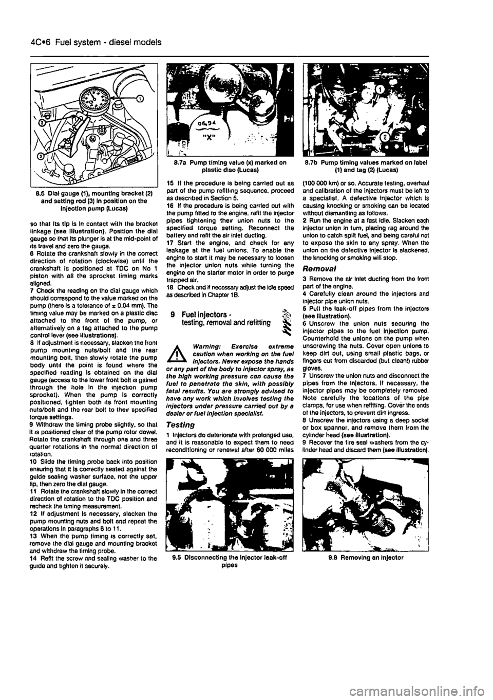
8.5 Dial gauge (1), mounting bracket (2) and setting rod (3) In position on the injection pump (Lucas)
so that Its tip Is In contact with the bracket linkage (see Illustration). Position the dial gauge so that its plunger is at the mid-point of its travel and zero the gauge. 6 Rotate the crankshaft slowly in the correct direction of rotation (clockwise) until the crankshaft is positioned at TDC on No 1 piston with ell the sprocket timing marks aligned. 7 Check the reading on the dial gauge which should correspond to the value marked on the pump (there is a tolerance of * 0.04 mm). The timing value may be marked on a plastic disc attached to the front of the pump, or alternatively on a tag attached to Ihe pump control lever (see illustrations). 8 If adjustment is necessary, slacken the front pump mounting nuts/bolt and the raar mounting bolt, then slowly rotate tne pump body until the point is found where the specified reading is obtained on the dial gauge (access to the lower front bolt is gained through the hole in the injection pump sprocket). When the pump Is correctly positioned, tighten both its front mounting nuta/bolt and the rear bolt to their specified torque settings. 9 Withdraw the timing probe slightly, so that it
8.7a Pump timing value (x) marked on plastic diso (Lucas)
15 If the procedure is being carried out as part of the pump refilling sequence, proceed as described in Section 5. 16 If the procedure is being carried out with the pump fitted to the engine, refit the injector pipes tightening their union nuts to the specified torque setting. Reconnect the battery and refit the air inlet ducting. 17 Start the engine, and check for any leakage at the fuel unions. To enable the engine to start it may be necessary to loosen tho injector union nuts while turning the engine on the starter motor in order to purge trapped air. 18 Check and If necessary adjust the Idle speed as described In Chapter 1B.
9 Fuel Injectors -testing, removal and refitting Sk ^
A
Warning: Exercise extreme caution when working on the fuel injectors. Never expose the hands or any part of the body to Injector spray, as the high working pressure can cause the fuel to pen ot rate the skin, with possibly fatal results. You are strongly advised to have any work which involves testing the injectors under pressure carried out by a dealer or fuel Injection specie list.
Testing 1 Injectors do deteriorate with prolonged uso, and it is reasonable to expect them to need reconditioning or renewal after 60 000 miles
8.7b Pump timing values marked on label (1) and tag (2) (Lucas)
(100 000 km) or so. Accurate testing, overhaul and calibration of the Injectors must be left to a specialist. A defective injector which Is causing knocking or smoking can be located without dismantling as follows. 2 Run the engine at a fast idle. Slacken each Injector union In turn, placing rag around the union to catch spilt fuel, and being careful not to exposa the skin to any spray. When tho union on the defective Injector is slackened, the knocking or smoking will stop.
Removal 3 Remove ihe air Inlet ducting from tho front part of the onglne. 4 Carefully clean around the Injectors and injector pipe union nuts. 5 Pull the leak-off pipes from the injectors (see illustration). 6 Unscrow the union nuts securing Ihe injector pipes to the fuel Injection pump. Counterhold the unions on the pump when unscrewing the nuts. Cover open unions lo keep dirt out, using small plastic bags, or fingers cut from discarded (but clean!) rubber gloves. 7 Unscrew the union nuts and disconnect the pipes from the ln|ectors, If necessary, the Injector pipes may be completely removed-Note carefully the locations of the pipe clamps, for use when refitting. Cover tho onds ot (he injectors, to prevent dirt ingress. 8 Unscrew the injectors using a deep socket or box spanner, and remove Ihem from the cylinder head (see Illustration). 9 Recover the tire seal washers from the cy-linder head and discard them (see illustration).
9.5 Disconnecting the Injector leak-off pipes 9.8 Removing an injector
Page 142 of 225
Fuel system - diesel models
4C*3
9.9 Removing the fire seal washor 9.13 Tightening an injector with a torque wrench
Refitting 10 Obtain new fire seal washers. 11 Take care not to drop the Injectors, or tfow the needles at their tips to become damaged. The injectors are prectsion-mado to Ine knits, and must not be handled roughly. In particular, never mount them in a bench vice. 12 Commence refitting by inserting the fire
seal
washers {convex face uppermost}. 13 Insert the injectors and tighten them to the specified torque (see illustration). 14 Refit the injector pipes and tighten the union nuts. Make sure the pipe clamps are in Iteir previously-noted positions. If the clamps
are
wrongly positioned or missing, problems may be expenenced with pipes breaking or splitting,
15 Reconnect the leak-off pipes. 16 Refit the air ducting. 17 Start the engine, and check for any leakage at the fuel unions. To enable the engine to start it may be necessary to loosen the Injector union nuts while turning the engine on the starter motor in order to purge trapped air.
10 Fuel gauge sender unit -removal and refitting
Refer to Chapter 4A, hov/ever note that the unit does not Incorporate a pump (see illustrations).
11 Fuel tank -removal and refitting
Refer to Chapter 4A, however note that in addition a safety valve with an anti-roll device is fitted in the top of the tank with a ventilation pipe to the front of the tank. The fuel gauge sender unit does not Incorporate a pump as this unit is located In the injection pump.
12 Inlet manifold - ^ removal and refitting %
Note: The Inlet and exhaust manifolds are both located on the rear of the engine and share the same securing bolts and gasket. Although the following procedure describes removal of the Inlet manifold separately it may be necessary to remove the exhaust manifold as well In order to renew the gasket.
Removal 1 Remove the air cleaner and ducting as described in Section 2. 2 Unbolt and remove the relay guard and bracket from the left-hand side of the engine. 3 On turbo models disconnect the air duct from the inlet manifold elbow. If necessary the elbow can be unbolted from the manifold and the sealing ring removed. 4 Unscrew the nuts securing the inlet manifold to the cylinder head noting the position of the support bracket. Note lhat some of the nuts also secure the exhaust manifold. Withdraw the inlet manifold from the studs (see illustrations), 5 Examine the gasket. If It is damaged it will be necessary to remove the exhaust manifold in order to renew it.
Refitting 6 Refitting Is a reversal of removal, but tighten all nuts and bolts lo the specified torque.
12.4c Removing the Inlet manifold
Page 157 of 225
5C«2 Preheating system - diesel models
2.3 No 4 glow plug showing the main supply lead end the interconnecting strap 2.5 Removing a glow plug
2 Glow plugs -removal, Inspection and refitting
Removal Caution: If the preheating system has just been energised, or If tho engine has been running, the glow plugs will be very hot
1 Disconnect the battery negative terminal (refer to Disconnecting the battery in the Reference Section of this manual), 2 Remove Ihe air Inlet ducting from the front of the engine with reference to Chapter 4C, Section 2. 3 Unscrew the nut from the relevant glow plug lerminai(s). and recover the washer(s). Note that tho main supply cable is connected to Number 4 cylinder glow plug and an interconnecting strap lis fitted between the four plugs (see Illustration). 4 Where applicable, carefully move any obstructing pipes or wires lo one side to enable access to the relevant glow plug(s). 5 Unscrew the glow plug(s) and remove from the cylinder head (see illustration).
Inspection 8 Inspect each glow plug for physical damage. Burnt or eroded glow plug tips can bo caused by a bad Injector spray pattern. Have the Injectors checked if this sort of damage is found. 7 If Ihe glow plugs are In good physical condition, check them electrically using a 12 volt test lamp or continuity tester as described in the previous Section. 8 The glow plugs can be energised by applying 12 volts to them to verity that they heat up evenly and In the required time. Observe the following precautions. a) Support the glow plug by clamping it carefully in a vice or selNocking pliers. Remember it will become red-hot. b) Make sura that the power supply or test lead incorporates a fuse or overload trip to protect against damage from a short-circuit. c) After testing, allow the glow plug to cool for several minutes before attempting to handle it. 9 A glow plug In good condition will start to glow red at the tip after drawing current for 5 seconds or so. Any plug which takes much longer to start glowing, or which starts
glowing in the middle instead of at the lip, « defective. Refitting 10 Refit by reversing the removal operations. Apply a smear of copper-based anti-seize compound to the plug threads and tighten Ihe glow plugs to Ihe specified torque. Do not overtighten, as this can damage the glow plug element.
3 Preheating system control unit -removal
and
refitting I
Removal 1 Disconnect the battery negative terminal (refer to Disconnecting the baffery In Ihe Reference Section of this manual). 2 Unscrew the screws and remove the relay cover located at the left-hand end of the engine. 3 Disconnect the wiring then remove the control unit from the bracket. Refitting 4 Refitting is a reversal of removal.
Page 177 of 225
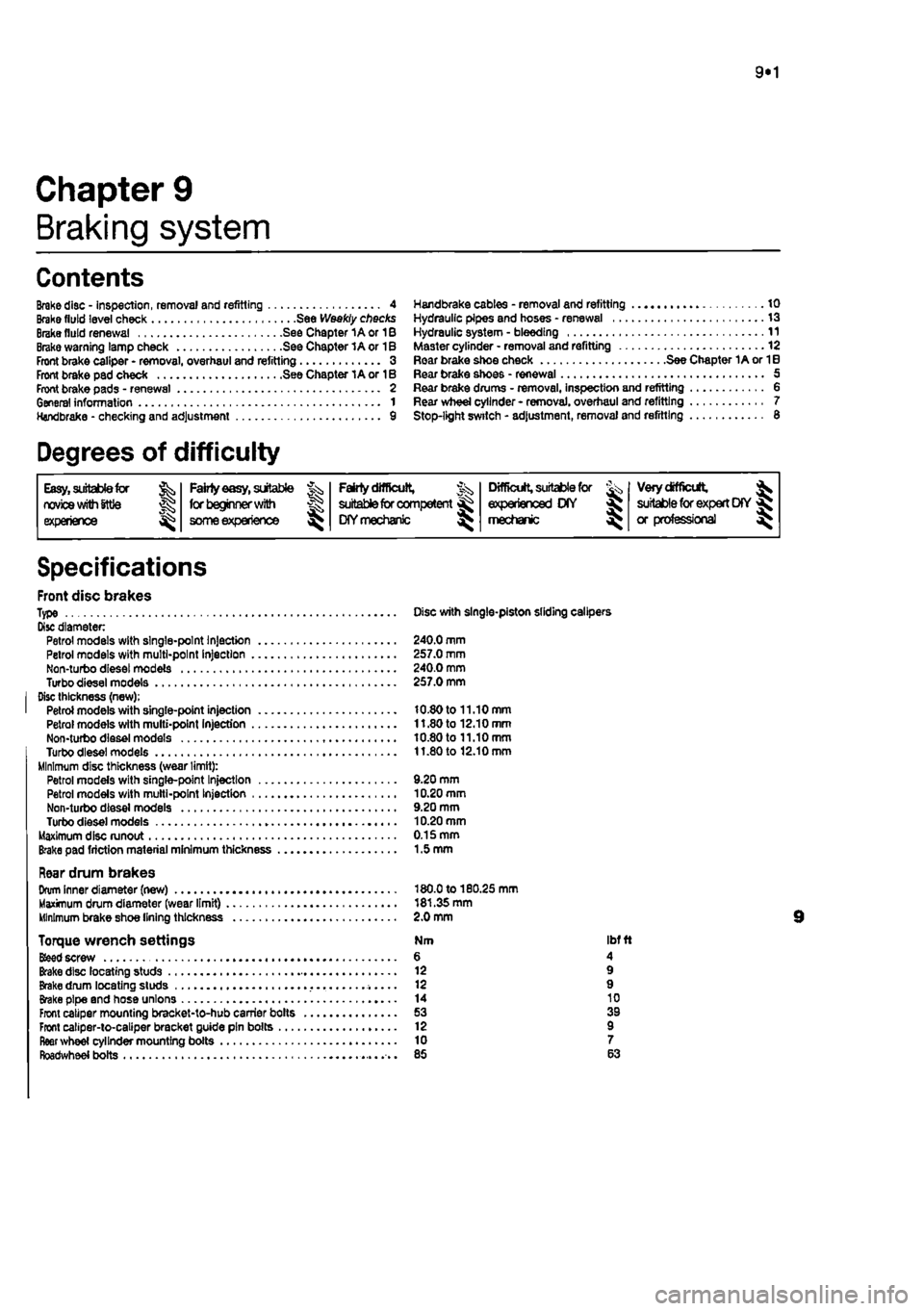
9«1
Chapter 9
Braking system
Contents
Brake disc - inspection, removal and refitting 4 Brake fluid level check See Weekly checks Brake fluid renewal See Chapter 1A or 1B Brake warning lamp check See Chapter 1A or 1B Front brake caliper - removal, overhaul and refitting 3 Front brake pad check See Chapter 1A or 1B Front brake pads - renewal 2 General information 1 Handbrake - checking and adjustment 9
Handbrake cables - removal and refitting 10 Hydraulic pipes end hoses - renewal 13 Hydraulic system - bleeding 11 Master cylinder - removal and refitting 12 Roar brake shoe check See Chapter 1A or 1B Rear brake shoes - renewal 5 Rear brake drums - removal, inspection and refitting 6 Rear wheel cylinder - removal, overhaul and refitting 7 Stop-light switch - adjustment, removal and refitting 6
Degrees of difficulty
Easy, suitable
far
novice with Sttle
experience ^
Fairly
easy,
suitable ^ (orbeginnerwith ®
some
experience
Fairly difficult, suitable
for
compe«ent ^ CHYmechanlc ^
Difficult, suitable for
experienced DIY « mechanic ^
Very difficult, ^
suitable
for
expert DIY
or professional ^
Specifications
Front disc brakes Type Disc with single-piston sliding calipers Disc diameter Petrol models with single-point Injection 240.0 mm Petrol models with multi-point Injection 257.0 mm Non-turbo diesel models 240.0 mm Turbodieselmodels 257.0 mm Disc thickness (new); Petrol models with single-point injection 10.80 to 11.10 mm Petrol models with multi-point Injection 11.80 to 12.10 mm Non-turbo diesel models 10.80 to 11.10 mm Turbodieselmodels 11.80 to 12.10 mm Minimum disc thickness (wear limit): Petrol models with single-pant Injection 9.20 mm Petrol models with multi-point Injection 10.20 mm Non-turbo diesel models 9.20 mm Turbo diesel models 10.20 mm Maximum disc runout 0.15 mm Brake pad friction material minimum thickness 1.5 mm
Rear drum brakes Drum Inner diameter (new) 180.0 to 180.25 mm Maximum drum diameter (wear limit) 181.35 mm Minimum brake shoe lining thickness 2.0 mm
Torque wrench settings Nm ibf ft
Bfeed
screw 6 4 Brake disc locating studs 12 9 Brake drum locating studs 12 9 Brake pipe and hose unions 14 10 Front caliper mounting bracket-to-hub carrier bolts 53 39 Front caliper-to-caliper bracket guide pin bolts 12 9 fleer wheel cylinder mounting boils 10 7 Roadwheel bolts 85 63
Page 186 of 225
9*10 Braking system
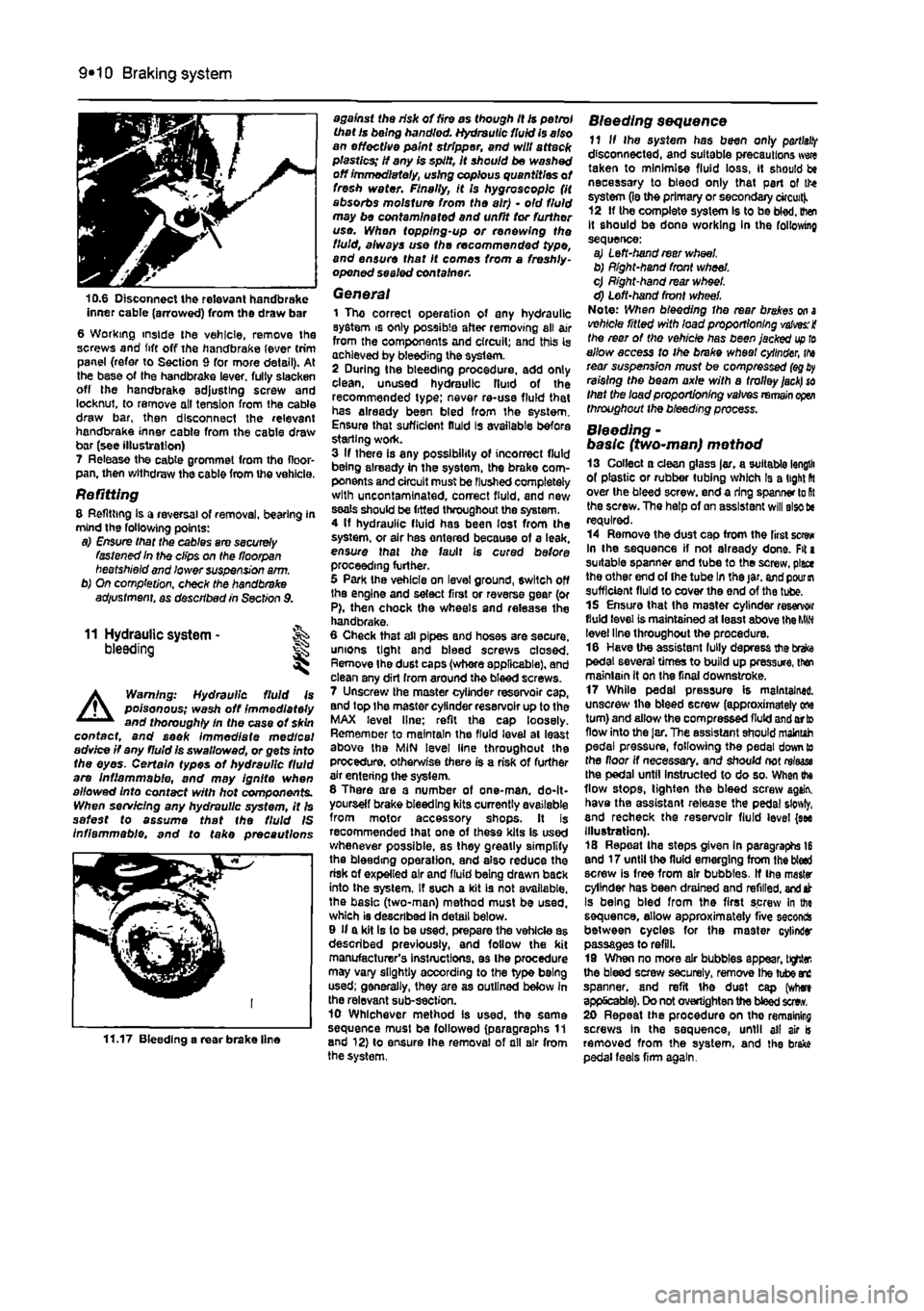
10.6 Disconnect the relevant handbrake inner cable (arrowed) from the draw bar 6 Working inside ihe vehicle, remove Ihe screws and lift off the handbrake lever trim panel (refer to Section 9 for more detail). At the base of the handbrake lever, full/ slacken off the handbrake adjusting screw and locknut, to remove oil tension from the cable draw bar, then disconnect the relevant handbrake inner cable from the cable draw bar (see illustration) 7 Release the cable grommet from tho floor-pan, then withdraw the cable from the vehicle.
Refitting 8 Refitting Is a reversal of removal, bearing in mind the following points: a) Ensure that the cables are securely fastened In the clips on the floorpan beetshield and lower suspension a/m. b) On completion, check the handbrake adiustment, as described in Section 9.
11 Hydraulic system -bleeding
A
Warning: Hydraulic fluid is poisonous; wash off immediately and thoroughly In the case ot skin contact, and seek immediate medical advice if any fluid is swallowed, or gets into the eyes. Certain types of hydraulic fluid are Inflammable, and may ignite when allowed into contact with hot components. When servicing any hydraulic system, it Is safest to assume that the fluid IS inflammable, and to take precautions
11.17 Bleeding a rear brake line
against the risk of fire as though it is petrol that Is being handled. Hydraulic fluid is also an effective paint stripper, and will attack plastics; If any is spilt, It should be washed off immediately, using copious quantities of fresh water. Finally, it Is hygroscopic (it absorbs moisture from the air) • old fluid may be contaminated and unfit tor further use. Whan topping-up or renewing the fluid, always use the recommended type, and ensure that It comes from a freshly-opened sealed container.
General 1 The correct operation of any hydraulic system is only possible after removing all air from the components and circuit; and this Is achieved by bleeding the syslem. 2 During the bleeding procedure, add only clean, unused hydraulic fluid of the recommended type; never re-use fluid that has already been bled from the system. Ensure that sufficient fluid is available before starting work. 3 If there is any possibility of incorrect fluid being already in the system, the brake com-ponents and circuit must be Flushed completely with uncontamlnated, correct fluid, and new seals should be fitted throughout the system. 4 If hydraulic fluid has been lost from the system, or air has ontered because of a leak, ensure that the fault is cured before proceeding further. 5 Park Ihe vehicle on level ground, switch off the engine and select first or reverse gear (or P), then chock the wheels and release the handbrake. 6 Cheek that all pipes and hoses are secure, unions tight and bleed screws closed. Remove Ihe dust caps (whore applicable), and clean any dirt from around the bleed screws. 7 Unscrew the master cylinder reservoir cap, and top Ihe master cylinder reservoir up to the MAX level line; refit the cap loosely. Rememoer to maintain the fluid level at least above the MIN level line throughout the procedure, otherwise there is a risk of further air entering the syslem. 8 There are a number of one-man. do-It-yourself brake bleeding kits currently available from motor accessory shops. It is recommended that one of these kits is used whenever possible, as they greatly simplify the bleeding operation, and also reduce the risk of expelled air and fluid being drawn back into the system. If such a kit is not available, the basic (two-man) method must be used, which is described in detail below. 9 If a kit Is to be used, prepare the vehicle as described previously, and follow the kit manufacturer's instructions, as Ihe procedure may vary slightly according to the type being used; generally, they are as outlined below in the relevant sub-section. 10 Whichever method is used, the same sequence must be followed (paragraphs 11 and 12) to ensure Ihe removal of all air from the system.
Bleeding sequence 11 If Ihe system has been only
partial!?
disconnected, and suitable precautions wwe taken to minimise fluid loss, it should be necessary to bteod only that part of the system (le the primary or secondary circuit). 12 If the complete system Is to be bled, then It should be done working in the following sequence: a) Left-hand rear wheel b) Right-hand front wheel. c) Right-hand rear wheel. d) Left-hand front wheel. Note: When bleeding the rear brakes
on a
vehicle ritled with load proportioning valves: i the rear of the vehicle has been jacked
up to
allow access to ihe brake wheel cylinder,
tha
rear suspension must be compressed
(eg
raising the beam axle with a trolley
jack) so
that the load proportioning valves
remain open
throughout the bleeding process.
Bleeding -basic (two~man) method 13 Collect a clean glass jar, a suitable length of plastic or rubber tubing which Is a light fit over the bleed screw, end a ring spanner lo
Rt
the screw. The help of an assistant will also tie required. 14 Remove the dust cap from the first screw In the sequence if not already done. Fit a suitable spanner and tube to the screw, place the other end of Ihe tube In the jar. and
pour in
sufficient fluid to cover the end of the tube. 15 Ensure that the master cylinder reservoir fluid level is maintained at least above the
MIN
level line throughout the procedure. 16 Have the assistant fully depress the brefce pedal several times to build up pressure, then maintain it on the final downstroke. 17 While pedal pressure is maintained, unscrew ihe bleed screw (approximately one turn) and allow the compressed fluid and orto flow into the
Jar,
The assistant should maintah pedal pressure, following the pedal down to the floor if necessary, and should not rrtaase Ihe pedal until instructed to do so. When ihe flow stops, tighten the bleed screw again, have the assistant retease the pedal sfowty, and recheck the reservoir fluid level (see Illustration). 18 Repeat Ihe steps given in paragraphs 16 end 17 until the fluid emerging from the bled screw is free from air bubbles. If Ihe master cylinder has been drained and refilled,
and
at Is being bled from the first screw In the sequence, allow approximately five seconds between cycles for the master cylinder passages to refill. 19 When no more air bubbles appear, tighter, the bleed screw securely, remove Ihe tube arc spanner, and refit the dust cap (where applicable). Do not overtighten the bleed sew. 20 Repeat the procedure on tho remaining screws In the sequence, until ail air is removed from the system, and the brake pedal feels firm again.
Page 187 of 225
Braking system 9®11
Bleeding • using a one-way valve kit 21 As their name implies, these kits consist ol a length of tubing with a one-way valve Fitted, to prevent expelled air and fluid being drawn back into the system; some kits include a translucent container, which can be positioned so that the air bubbles can be more easily seen flowing from the end of the tube. 22 The kit is connected to the bleed screw, which is then opened. The user returns to the driver's seat, depresses the brake pedal with a smooth, steady stroke, and stowty releases it; this is repeated until the expelled fluid is clear of air bubbles. 23 Note that these kits simplify work so much that It is easy lo forget the master cylinder reservoir fluid level; ensure that this Is maintained at least above the MIN level line at all times.
Bleeding -using a pressure-bleeding kit 24 These kits are usually operated by the reservoir of pressurised air contained in the spare tyre. However, note that it will probably be necessary to reduce the pressure lo a lower level than normal; refer to the instructions supplied with the kit. 2$ By connecting a pressurised, fluid-filled container to the master cylinder reservoir, bleeding can be carried out simply by opening each screw In turn (in the specified sequence), and allowing the fluid to flow out until no more air bubbles can be seen in the expelled fluid. 28 This method has the advantage that the large reservoir of fluid provides an additional safeguard against air being drawn into the system during bleeding. 27 Pressure-bleeding is particularly effective when bleeding 'difficult' systems, or when bleeding the complete system at the time of routine fluid renewal.
All methods 28 When bleeding is complete, and firm pedal feel is restored, wash off any split fluid, lighten the bleed screws securely, and refit their dust caps (where applicable). 29 Check the hydraulic fluid level in the master cylinder reservoir, and top-up if necessary. 30 Discard any hydraulic fluid thai has been Wed from the system; it will not be fit for re-use. 91 Check the feel of the brake pedal. If it feels at all spongy, air must still be present in Vie system, and further bleeding is required. Failure to bleed satisfactorily after a reasonable repetition of the bleeding procedure may be due to worn master cylinder seals.
12 Master cylinder- % removal
and
refitting SK
A
Warning: 8efore starting work, refer to the warning at the beginning of Section 11 concerning the dangers of hydraulic fluid.
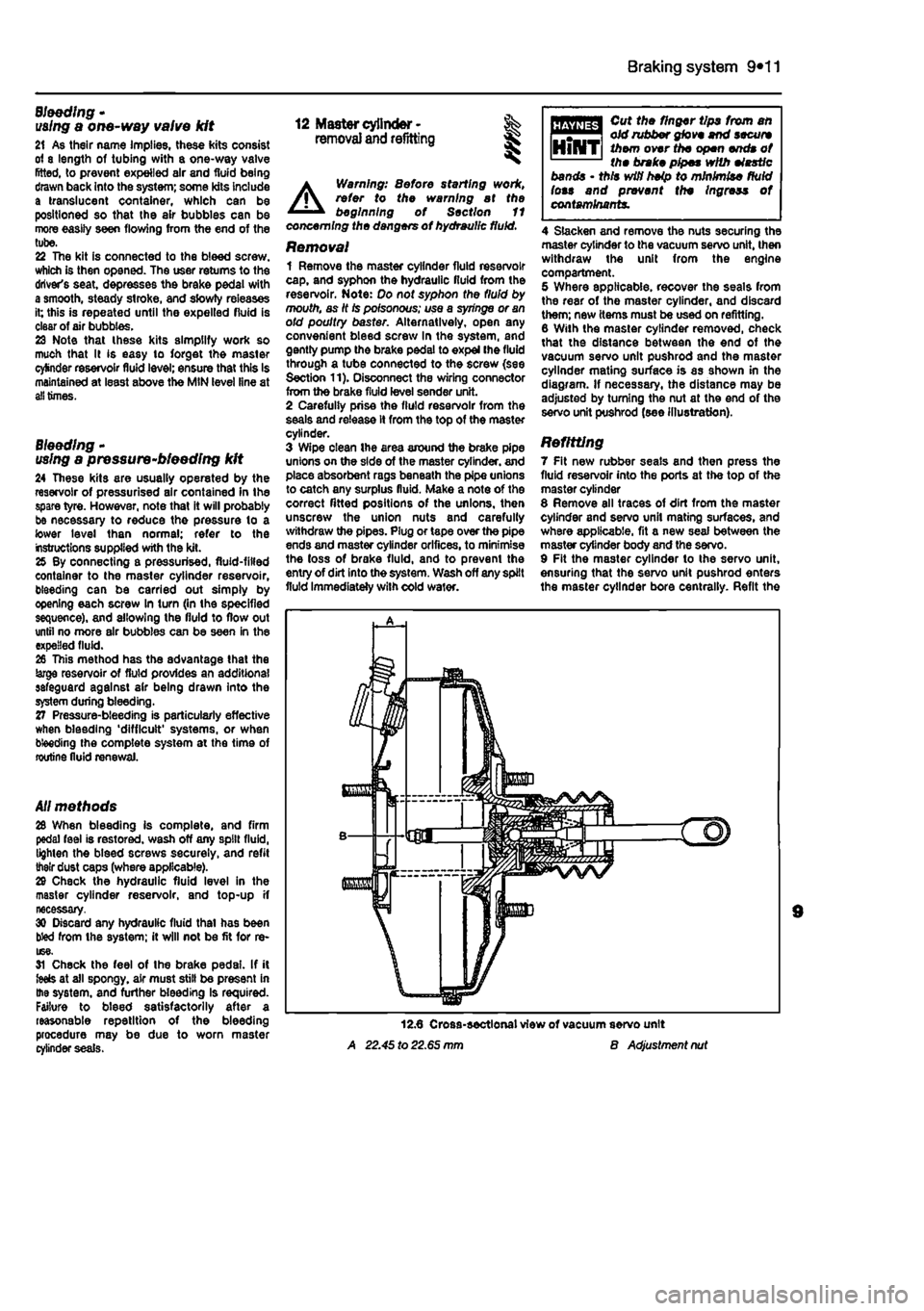
Removal 1 Remove the master cylinder fluid reservoir cap, and syphon the hydraulic fluid from the reservoir. Note: Do not syphon the fluid by mouth, as It Is poisonous; use a syringe or an old poultry baster. Alternatively, open any convenient bleed screw In the system, and gently pump the brake pedal to expel (he fluid through a tube connected to the screw (see Section 11). Disconnect the wiring connector from the brake fiuld level sender unit. 2 Carefully prise the fiuld reservoir from the seals and release it from the top of the master cylinder. 3 Wipe clean Ihe area around the brake pipe unions on the side of the master cylinder, and place absorbent rags beneath the pipe unions to catch any surplus fluid. Make a note of the correct fitted positions of the unions, then unscrew the union nuts and carefully withdraw the pipes. Plug or tape over the pipe ends and master cylinder orifices, to minimise the loss of brake fluid, and to prevent the entry of dirt into the system. Wash off any spilt fluid immediately with cold wafer.
A 22.45 to 22.65 mm
Cut the finger tips from an old rubber glove end secure them over the open ends of the brake pipes with elastic bands • this wifi heip to minimise fluid lots and prevent the Ingress of contaminants.
4 Slacken and remove the nuts securing the master cylinder to the vacuum servo unit, then withdraw the unit from the engine compartment. 5 Where applicable, recover the seals from the rear of the master cylinder, and discard them; new items must be used on refitting. 8 With the master cylinder removed, check that the distance between the end of the vacuum servo unit pushrod and the master cylinder mating surface is as shown in the diagram. If necessary, the distance may be adjusted by turning the nut at the end of the servo unit pushrod (see illustration).
Refitting 7 Fit new rubber seals and then press the fluid reservoir into the ports at the top of the master cylinder 8 Remove all traces of dirt from the master cylinder and servo unit mating surfaces, and where applicable, fit a new seal between the master cylinder body and the servo. 9 Fit the master cylinder to the servo unit, ensuring that the servo unit pushrod enters the master cylinder bore centrally. Refit the
B Adjustment nut
Page 188 of 225
9*12 Braking system
master cylinder mounting nuts, and tighten them securely. 10 Wipe clean the brake pipe unions, then refit them to the correct master cylinder ports, as noted before removal, and lighten the union nuts securely. 11 Refill tha master cylinder reservoir with new fluid, and bleed the complete hydraulic system as described In Section 11. 12 Check the operation of the braking system thoroughly.
13 Hydraulic pipes and hoses - % renewal S§
A
Warning: Before starting work, refer to the warning at the beginning of Section 11 concerning the dangers of hydraulic fluid, 1 If any pipe or hose is to be renewed, minimise fluid loss by first removing the master cylinder reservoir cap. then tighten the cap down onto a piece of polythene to obtain
an airtight seal. Alternatively, flexible hoses can be sealed, If required, using a proprietary brake hose clamp; metal brake pipe unions can be plugged (if care Is taken not to allow dirt into the system) or capped immediately they are disconnected. Place a wad of rag under any union that is to be disconnected, to catch any spilt fluid-2 If a flexible hose Is to be disconnected, unscrew the brake pipe union nut before removing the spring clip which seeurea the hose to its mounting bracket. 3 To unscrew the union nuts, ll is preferable lo obtain a brake pipe spanner of the correct size; these are available from most large molor accessory shops. Failing this, a close-fitting open-ended spanner will be required, though if the nuts are tight or corroded, their flats may be rounded-off if the spanner slips. In such a case, a self-locking wrench is often the only way to unscrew a stubborn union, but It follows that Ihe pipe and the damaged nuts must be renewed on reassembly. Always clean a union and surrounding area before disconnecting it If disconnecting a compo-
nent with more than one union, make a carefJ note of the connections before disturbing
any
of them. 4 If a brake pipe Is to be renewed, it can b« obtained, cut to length and with the union nuts and end flares in place, from Fiat dealers. All that is then necessary is to bend It to shape, following the line of the original, baton fitting It to the vehicle. Alternatively, most motor accessory shops can make up bra Ha pipes from kits, bul this requires very carefii measurement of the original, to ensure (hat the replacement is of the correct length. Tha safest answer is usually to take the original lo the shop as a pattern. 5 On refitting, do not overtighten the union nuts. It is not necessary to exercise brute force to obtain a sound joint. 6 Ensure that the pipes and hoses an correctly routed, with no kinks, and that they are secured in the clips or brackets provided. After fitting, remove the polythene from lbs reservoir, and bleed the hydraulic system
88
described In Section 11. Wash off any split fluid, and check carefully for fluid leaks.
Page 198 of 225
10*10 Suspension and steering
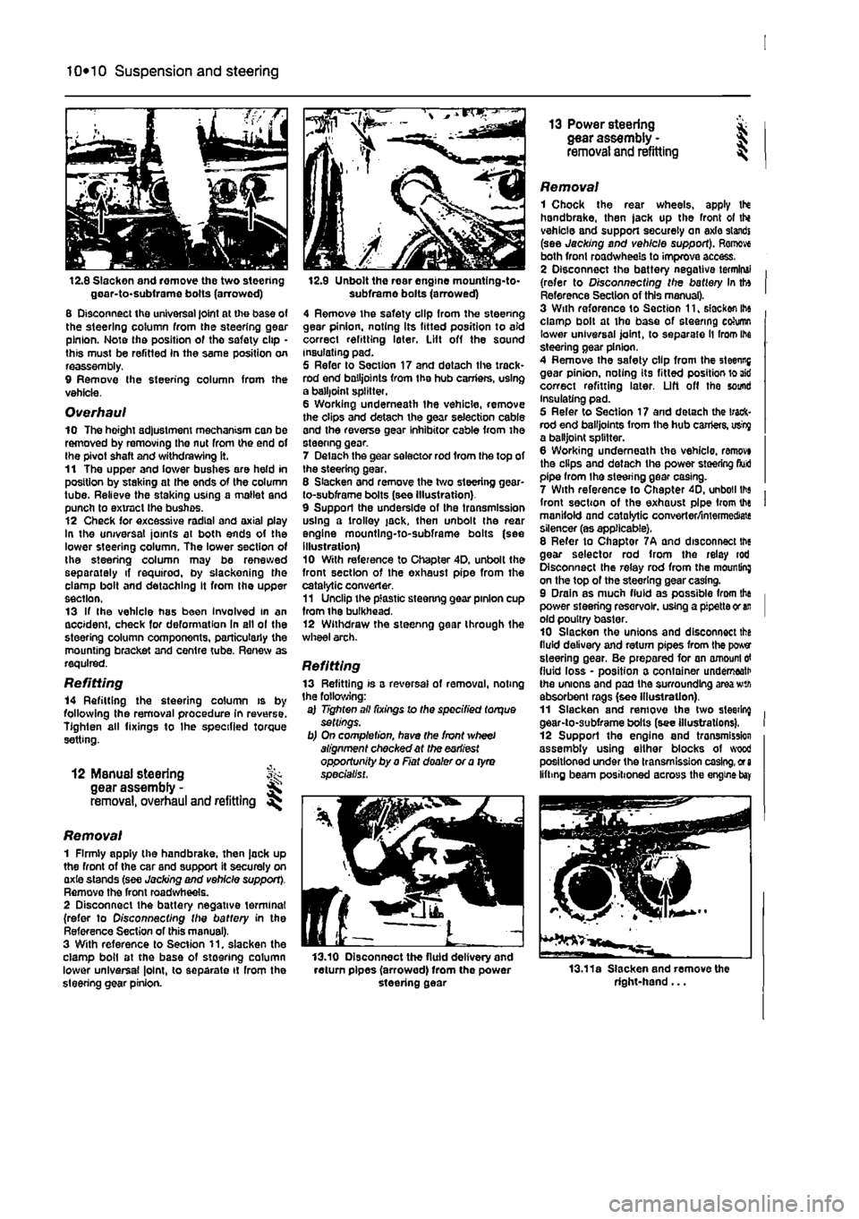
12.8 Slacken and remove the two steering goar-to-subirame bolts (arrowed) 8 Disconnect the universal joint at the base of the steering column from the steering gear pinion. Note the position of tho safety clip • this must be refitted In the same position on reassembly. 9 Remove Ihe steering column from the vehicle.
Overhaul 10 The hoight adjustment mechanism can be removed by removing the nut from the end of the pivot shaft and withdrawing it. 11 The upper and lower bushes are held in position by staking at the ends of the column tube. Relieve the staking using a mallet and punch to extract the bushes. 12 Check for excessive radial and axial play In the universal joints at both ends of the lower steering column. The lower section of the steering column may be renewed separately if required, by slackening the clamp bolt and detaching It from the upper section. 13 If the vehicle has been Involved in an accident, check for deformation In all ol the steering column components, particularly the mounting bracket and centre tube. Renew as required.
Refitting 14 Refitting the steering column is by following the removal procedure in reverse. Tighten all fixings to Ihe specified torque setting.
12 ManuaJ steering fk gear assembly -removal, overhaul and refitting
Removal 1 Firmly apply the handbrake, then jack up the front of the car and support it securely on axie stands (see Jacking and vehicle support). Remove the front road wheels. 2 Disconnect the battery negative terminal (refer to Disconnecting the battery in the Reference Section of this manual). 3 With reference to Section 11. slacken the clamp boil at the base of steering column lower universal |o!nt, to separate it rrom the steering gear pinion.
12.9 Unbolt the rear engine mountlng-to-subframe bolts (arrowed) 4 Remove the safety clip from the steering gear pinion, noting Its fitted position to aid correct refitting later. Lift off the sound insulating pad. 5 Refer to Section 17 and dotach the track* rod end bailjoints from the hub carriers, using a balljoint splitter. 6 Working underneath the vehicle, remove the clips and detach the gear selection cable and the reverse gear inhibitor cable from the steenng gear. 7 Delach the gear selector rod from the top of the steering gear, 8 Slacken and remove the two steering gear-to-subframe bolts (see Illustration) 9 Support the underside of the transmission using a trolley jack, then unbolt the rear engine mountlng-to-subframe bolts (see illustration) 10 With reference to Chapter 4D. unbolt the front section of the exhaust pipe from the catalytic converter. 11 Unclip the plastic steenng gear pinion cup from ihe bulkhead. 12 Withdraw the steenng gear through the wheel arch.
Refitting 13 Refitting is a reversal of removal, noting the following: a) Tighten all fixings lo the specified torque settings. b) On completion, have the front wheel alignment checked at the earliest opportunity by a Fiat dealer or a tyro specialist.
13.10 Disconnect the fluid delivery and return pipes (arrowed) from the power steering gear
13 Power steering * gear assembly - J removal and refitting ^
Removal 1 Chock the rear wheels, apply tN handbrake, then jack up the front ot thi vehicle and support securely on axle standi (see Jacking and vehicle support). Remove both front roadwheels to improve access. 2 Disconnect the battery negative terminal (refer to Disconnecting the battery In tto Reference Section of this manual). 3 With reforence to Section 11, slacken ihe clamp bolt at the base of steering cohimn lower universal joint, to separate ll from Ihe steering gear pinion. 4 Remove the safety clip from the steenng gear pinion, noting its fitted position lo aid correct refitting later. Lift off the sound Insulating pad. 5 Refer to Section 17 and detach the track-rod end bailjoints from the hub carriers, usty a balljoint splitter. 6 Working underneath the vehicle, ranwvi the clips and detach the power steering fluid pipe from the steering gear casing. 7 With reference to Chapter 40, unboil lbs front section of the exhaust pipe from the manifold and catalytic converter/intermediate silencer (as applicable). 8 Refer to Chaptor 7A and disconnect the gear selector rod from the relay rod Disconnect the relay rod from the mounting on the top of the steering gear casing. 9 Drain as much fluid as possible from the power steering reservoir, using a pipette or
an
old poultry baster. 10 Slacken the unions and disconnect the fluid delivery and return pipes from the power steering gear. Be prepared for an amount
erf
fluid loss - position a container underneath the unions and pad the surrounding area wth absorbent rags (see Illustration). 11 Slacken and remove the two sleeting gear-to-subframe bolts (see illustrations). 12 Support the engine and tronsmission assembly using either blocks of wood positioned under the transmission casing,
or a
lifting beam positioned across the engine
bay
13.11a Slacken and remove the right-hand...
Page 203 of 225
11 *2 Bodywork and fittings
on vehicles with wax-based underbody protective coating, or the coating will be removed. Such vehicles should be inspected annually, preferably just prior lo Winter, when the underbody should be washed down, and any damage to the wax coating repaired. Ideally, a completely fresh coat should be applied. It would also be worth considering the use of such wax-based protection for injection into door panels, sills, box sections, etc, as an additional safeguard against rust damage, where such protection Is not provided by the vehicle manufacturer. After washing paintwork, wipe off with a chamois feather to give an unspotted clear finish. A coat of clear protective wax polish wilt give added protection against chemical pollutants in the air. If the paintwork sheen has duiled or oxidised, use a cleaner/polisher combination to restore the brilliance of the shine. This requires a little effort, but such dulling Is usually caused because regular washing has been neglected. Care needs to be taken with metallic paintwork, as special non-abrasive cleaner/polisher is required to avoid damage to the finish, Always check that the door and ventilator opening drain holes and pipes are completely clear, so that water can be drained out. Brightwork should be treated In the same way as paintwork. Windscreens and windows can be kept clear of the smeary film which often appears, by the use of proprietary glass cleaner. Nover use any form of wax or other body or chromium polish on glass.
Maintenance -upholstery and carpets
Mats and carpets should be brushed or vacuum-cleaned regularly, to keep them free of grit. If they are badly stained, remove them from the vehicle for scrubbing or sponging, and make quite sure they are dry before refitting. Seats and interior trim panels can be kept clean by wiping with a damp cloth. If they do become stained (which can be more apparent on light-coloured upholstery), use a little liquid detergent and a soft nail brush lo scour the grime out of the grain of the material. Do not forget to keep the headlining clean in the same way as the upholstery. When using liquid cleaners inside the vehicle, do not over-wet the surfaces being cleaned. Excessive damp could get Into the seams and padded interior, causing stains, offensive odours or even rot.
If the Inside of the vehicle gets wet accidentally, tt Is worthwhile taking some trouble to dry ft out property, particularly where carpets an involved. Do not leave oil or electric heaters inside the vehicle for this purpose.
4 Minor body damage -repair
Repairs of minor scratches In bodywork If the scratch Is very superficial, and does not penetrate to the metal of the bodywork, repair is very simple. Lightly rub the area of the scratch with a paintwork renovator, or a very fine cutting paste, to remove loose paint from the scratch, and to clear the surrounding bodywork of wax polish, Rinse the area with clean water. Apply touch-up paint to ihe scratch using a fine paint brush; continue to apply fine layers of paint until the surface of the paint In the scratch Is level with the surrounding paintwork. Allow Ihe new paint at least two weeks to harden, then blend it Into the surrounding paintwork by rubbing the scratch area with a paintwork renovator or a very fine cutting paste. Finally, apply wax polish. Where the scratch has penetrated right through to the metal of the bodywork, causing the metal to rust, a different repair technique Is required. Remove any loose rust from the bottom of the scratch with a penknife, then apply rust-inhibiting paint to prevent the formation of rust in the future. Using a rubber or nylon applicator, fill the scratch with bodystopper paste. If required, this paste can be mixed with cellulose thinners to provide a very thin paste which is ideal for filling narrow scratches. Before the stopper-paste in Ihe scratch hardens, wrap a piece of smooth cotton rag around the top of a finger. Dip the finger in cellulose thinners, and quickly sweep it across the surface of the stopper-paste in the scratch: this will ensure that the surface of the stopper-paste is slightly hollowed. The scratch can now be painted over as described earlier In this Section.
Repairs of dents in bodywork When deop denting of the vehicle's bodywork has taken place, the first task is to put) the dent out. until the affected bodywork almost attains rts onginal shape. There is little polnl in trying to restore Ihe original shape completely, as the metal in the damaged area will have stretched on impact, and cannot be reshaped fully to its original contour. It Is better to bring the level of the dent up to a point which is about 3 mm below the level of the surrounding bodywork. In cases where Ihe dent is very shallow anyway, It is not worth trying to pull it out at all. If the underside of the dent is accessible, it can be hammered out gently from behind, using a mallet with a wooden or plastic head, Whilst doing this, hold a suitable block of wood firmly against (he outside of Ihe panel, to absorb the impact from the hammer blows and thus prevent a large area of the bodywork from being 'belled-out".
Should the dent be In a section of (I* bodywork which has a double skin, or seme other factor making It Inaccessible from behind, a different technique is called for. Dull several small holes through the metal inside Ihe area - particularly in the deeper section. Then screw long self-tapping screws Into the holes, just sufficiently for them to gain a good purchase in the metal. Now the dent can be pulled out by pulling on the protruding heads of the screws with a pair of pliers. The next stage of the repair Is the removal of the paint from the damaged area, and from an inch or so of the surrounding 'sound' bodywork. This is accomplished most easily by using a wire brush or abrasive pad on a posver drill, although it can be done just as effectively by hand, using sheets of abrasive paper. To complete the preparation for filling, score the surface of the bare metal wflhi screwdriver or the tang of 8 file, or alternatively, drill small holes In the affected area. This will provide a really good 'key' for the filler paste. To complete the repair, see the Section on filling and respraying.
Repairs of rust holes or gashes in bodywork Remove all paint from the affected area, and from an inch or so of the surrounding 'sound' bodywork, using an abrasive pad
or a
wire brush on a power drill. If these are not available, a few sheets of abrasive paper wil do the job most effectively. With the paint removed, you will be able to judge the severity of the corrosion, and therefore decide whether to renew the whole panel (if this is possible) or to repair the affected area. New body panels are not as expansive as most people think, and it is often quicker and more satisfactory to fit a new panel than to attempt to repair large areas of corrosion. Remove all fittings from Ihe affected area, except those which will act as a guide to ttie original shape of the damaged bodywork (eg headlight shells etc). Then, using tin snips
or a
hacksaw blade, remove all loose metal snd any other metal badly affected by corrosion. Hammer the edges of the hole inwards, in order to create a slight depression for the filer paste. Wire-brush the affected area to remove tha powdery rust from the surface of the remaining metal. Paint Ihe affected area with rust-inhibiting paint, if the beck of the rusted area is accessible, treat this also. Before filling can take place, ft will be necessary to block the hole in some
way.
TNs can be achieved by the use of aluminium cr plastic mesh, or aluminium tape. Aluminium or plastic mesh, or glass-fibre matting, is probably the best material to use for a large hole. Cut a piece to tha approximate size and shape of tho hole to b« filled, then position it In the hole so that its edges are below the level of the surrounding bodywork. It can be retained in position by