tailgate FIAT PUNTO 1998 176 / 1.G Workshop Manual
[x] Cancel search | Manufacturer: FIAT, Model Year: 1998, Model line: PUNTO, Model: FIAT PUNTO 1998 176 / 1.GPages: 225, PDF Size: 18.54 MB
Page 16 of 225
Weekly checks 015
Automatic transmission fluid level
Before you start: • Park the vohicle on level ground, and apply the handbrake firmly. Let the engine idle, and select P or N.
Safety First! • The need for frequent topping-up indicates a leak, which should bo Investigated immediately.
I
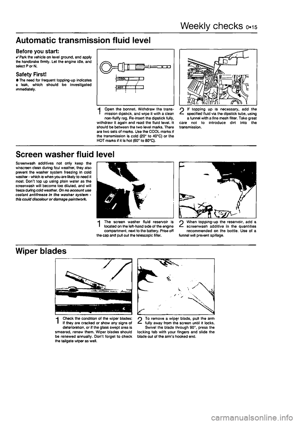
Open the bonnet. Withdraw the trans-mission dipstick, and wipe it with a clean non-fluffy rag. Re-Insert the dipstick fully, withdraw it again and read the fluid level. II should be between (he two level marks. There are two sets of marks. Use the COOL marks if the transmission is cold (20" to 40°C) or the HOT marks if it Is hot (60" to 809C).
2
If topping up fs necessary, add the specified fluid via the dipstick tube, using a funnel with a fine mesh filter. Take great care nol to introduce dirt into the transmission.
Screen washer fluid level
Screenwash additives not only keep the wlnscreen clean during foul weather, they also prevent the washer system freezing kn cold weather • which is when you are likely to need it most. Don't top up using plain water as the screenwash will become too diluted, and will freeze during cold weather. On no account use coolant antifreeze In the washer system • this could discolour or damage paintwork.
3H
m
I
The screen washer fluid reservoir is located on the left-hand side of the engine compartment, next to the battery. Prise off the cap and pull out the telescopic filler.
2
When topping-up the reservoir, add a screenwash additive In the quantities recommended on the bottle. Use of a funnel wilt prevent spillage.
Wiper blades
1
Check the condition of the wiper blades; if they are cracked or show any signs of deterioration, or if the glass swept area is smeared, renew them. Wiper blades should be renewed annually. Don't forget to check the tailgate wiper as well.
2
To remove a wiper blade, pull the arm fully away from the screen until It locks. Swivel the blade through 90", press the locking tab with your fingers and slide the blade out of the arm's hooked end.
Page 32 of 225
Every 20 000 miles - petrol models 1A.13
20 Ignition system check
81
21 Engine management system check
A
Warning: Voltages produced by an electronic ignition system are considerably higher than those produced by conventional ignition systems. Extreme care must be taken when working on the system with the Ignition switched on. Persons with surgically-Implanted cardiac pacemaker devices should keep well clear of the ignition circuits, components and test oquipment. 1 The ignition system components should be checked for damage or deterioration as follows.
General component check 2 The spark plug (HT) leads should be checked whenever new spark plugs are fitted. 3 Pull the leads from the plugs by gripping
the end
fitting, not the lead, otherwise the lead connection may be fractured.
Ensure that the leads are i numbered before removing i them, to avoid confusion when refitting
4 Check Inside the end fitting for signs of corrosion, which will look like a white crusty powder. Push the end fitting back onto the spark plug, ensuring that it is a tight fit on the plug. if not, remove the lead again and use pliers to carefully crimp the metal connector inside the end fitting until it fits securely on the
end
of the spark plug. 5 Using a clean rag, wipe Ihe emlre length of the lead to remove any built-up dirt and grease. Once the lead is clean, check for bums, cracks and other damage. Do not bend the lead excessively, nor pull the lead lengthways - the conductor inside might break. 6 Disconnect the other end of the lead from the ignition coll. Again, pull only on the end fitting. Check for corrosion and a tight fit in the
same
manner as the spark plug end. Refit the bad securely on completion. 7 Check the remaining leads one at a time, in
ihe same
way. 8 if new spark plug (HT) leads are required, purchase a set for your specific car and engine. 9 Even with the ignition system In first-class condition, some engines may still occasionally experience poor starting attributable to damp ignition components. To disperse moisture, a water-dispersant aerosol should be liberally
Ignition timing -
check
and adjustment 10 Check the ignition timing as described In Chapter 58.
1 This check is part of the manufacturer's maintenance schedule, and Involves testing Ihe engine management system using special dedicated test equipment. Such testing will allow the test equipment to read any fault codes stored in the electronic control unit memory. 2 Unless a fault is suspected, this test te not essential, although it should be noted that it is recommended by the manufacturers. 3 If access to suitable test equipment is not possible, make a thorough check of all ignition, fuel and emission control system components, hoses, and wiring, for security and obvious signs of damage. Further details of the fuet system, emission control system and ignition system can be .found In the relevant parts of Chapters 4 and 5.
22 Hinge and lock lubrication %
1
1 Lubricate the hinges of the bonnet, doors and tailgate with a light general-purpose oil. Similarly, lubricate ail latches, locks and lock strikers. At the same time, check the security and operation of all the locks, adjusting them If necessary (see Chapter 11). 2 Lightly lubricate the bonnet release mechanism and cable with a suitable grease.
23 Headlight beam adjustment % & ^
1 Accurate adjustment of the headlight beam is only possible using optical beem-setting equipment, and this work should therefore be carried out by a Fiat dealer or service station with the necessary facilities. In an emergency, however, the following procedure will provide an acceptable light pattern. 2 Position the car on a level surface with tyres correctly inflated, approximately 10 metres in front of. and at right-angles to, a wall or garage door, 3 Draw a horizontal line on the wall or door at headlamp centre height. Draw a vertical line corresponding to the centre line of the car, then measure off a point either side of this, on the horizontal line, corresponding with the headlamp centres. 4 Switch on the main beam and check that the areas of maximum illumination coincide with the headlamp centre marfcs on Ihe wall, if not. turn the adjustment screw located on the upper inside edge of the headlight unit to adjust the beam laterally, and the adjustment screw located on the upper outside edge of the headlight unit to adjust the beam
vertically. On models with electric headlight adjustment, make sure that it is set at its basic setting before making the adjustment.
24 Road test
Instruments and electrical equipment 1 Check the operation of all Instruments and electrical equipment. 2 Make sure that all instruments read correctly, and switch on all electrical equipment in turn, to check that it functions properly.
Steering and suspension 3 Check for any abnormalities in the steering, suspension, handling or road feel. 4 Drive the vehicle, and check that there are no unusual vibrations or noises. 5 Check that the steering feels positive, with no excessive sloppiness, or roughness, and check for any suspension noises when cornering and driving over bumps.
Drivetrain 6 Check the performance of the engine, clutch (where applicable), transmission and driveshafts. 7 Listen for any unusual noises from the engine, clutch and gearbox/transmission. 8 Make sure that the engine runs smoothly when Idling, and that there Is no hesitation when accelerating. 9 Check that, where applicable, the clutch action Is smooth and progressive, that the drive is taken up smoothly, and that the pedal travel is not excessive. Also listen for any noises when the clutch pedal is depressed. 10 On manual gearbox models, check that all gears can be engaged smoothly without noise, and that the gear lever action is not abnormally vsgue or notchy. 11 On automatic transmission models, check that all Ihe gear positions can be selected with the vehicle at rest, if any problems are found, they should be referred to a Flat dealer. 12 Listen for a metallic clicking sound from the front of the vehicle, as the vehicle is driven slowly in a circle with the steering on full-lock. Carry out this check in both directions. If a clicking noise is heard, this Indicates wear in a drtveshaft joint, In which case renew the joint if necessary.
Check the braking system 13 Make sure that the vehicle does not pull to one side when braking, and that the wheels do not lock prematurely when braking hard. 14 Check that there is no vibration through the steering when braking. 15 Check that the handbrake operates correctly without excessive movement of the lever, and that It holds the vehicle stationary on a slope.
Page 36 of 225
Every 2 years - petrol models ia.i?
check, and if necessary top-up, the level in the expansion tank. Refit the cap on completion. Antifreeze mixture 22 The antifreeze should always be renewed at the specified Intervals. This is necessary not only to maintain the antifreeze properties, but also to prevent corrosion which would otherwise occur as the corrosion inhibitors
beoome
progressively less effective. 23 Always use an ethylene-glycol based antifreeze which Is suitable for use In mixed-metal cooling systems, The quantity of antifreeze and levels of protection are
Indicated In
the Specifications. 24 8efore adding antifreeze, the cooling system should be completely drained, preferably flushed, and all hoses checked for condition and security. 25 After filling with antifreeze, a label should
be attached
to the expansion tank, stating the type and concentration of antifreeze used, and the date installed. Any subsequent lopping-up should be made with the same
type and
concentration of antifreeze. 26 Do not use engine antifreeze In the windscreen/tailgate washer system, as it will
cause damage to the vehicle paintwork. A screenwash additive should be added to the washer system in the quantities stated on the bottle.
34 Brake fluid renewal | I
A
Warning: Brake hydraulic fluid can harm your eyes and damage painted surfaces, so use extreme caution when handling and pouring H. Do not use fluid that has been standing open for some t/me, as it absorbs moisture from the air. excess moisture can cause a dangerous ioss of braking effectiveness. 1 The procedure is similar to that for the bleeding of the hydraulic system as described in Chapter 9, except that the brake fluid reservoir should be emptied by siphoning, using a clean poultry baster or similar before starting, and allowance should be made for the old fluid to be expelled when bleeding a section of the circuit. 2 Working as described In Chapter 9, open the first bleed screw in the sequence, and
pump the brake pedal gently until nearly all the old fluid has bsen emptied from the master cylinder reservoir.
Old hydraulic fluid Is Invariably much darker In colour than the new, making It easy to distinguish the two.
3 Top-up to the MAX level with new fluid, and continue pumping until onty the new fluid remans in the reservoir, and new fluid can be seen emerging from the bleed screw. Tighten the screw, and top the reservoir level up to the MAX level line. 4 Work through all the remaining bleed screws in the sequence until new fluid can be seen at all of them. Be careful to keep the master cylinder reservoir topped-up to above the MIN level et all times, or air may enter the system and greatly increase the length of the task. 5 When the operation Is complete, check that all bleed screws are securely tightened, and that their dust caps are refitted. Wash off all traces of spilt fluid, and recheck the master cylinder reservoir fluid level. 6 Check the operation of the brakes before taking the car on the road.
1A
Page 47 of 225
Every 20 000 miles - diesel models ib.h
18
Valve clearance check and
adjustment
1 The Importance of having the valve clearances correctly adjusted cannot be Distressed, as they vitally affect the performance of the engine. Adjustment should only be necessary when the valve gear nas become noisy, after engine overhaul, or when trying to trace the cause of power loss. The clearances are checked as follows. The engine must be cold for the check to be ttcurate. 2 Apply the handbrake then jack up the right-hand front of the vehicle and support on an axle stand (see Jacking and vehicle support). Engage 4th gear. The engine can now be rotated by turning the right-hand front roadwfteei. 3 Remove ail four glove plugs as described In Chapter 5C. 4 Remove the air cleaner cover and air duct
then
remove the camshaft cover as described
in
Chapter 2C. 6 Each valve clearance must be checked wnen the high point of the cam is pointing directly upward away from the cam follower. 6 Check the clearances in the firing order 1-3-4-2, No 1 cylinder being at the timing belt end of the engine. This will minimise the amount of crankshaft rotation required. 7 Insert the appropriate feeler blade between
the heel
of the cam and the cam follower shim of the First valve (see Illustration). If necessary alter the thickness of the feeler blade until it is a stiff, sliding fit. Record the thickness, which will, of course, represent the
vafve
clearance tor Ihis particular valve. 8 Turn the engine, check the second valve devance and record it. t Repeat the operations on all the remaining valves. recording their respective clearances. 10 Remember that the clearance for inlet and exhaust valves differs - see Specifications. Counting from the timing cover end of the
engine,
the valve sequence is: Wef 2-4-5-7 Etfiat/sf 7-3-6-8
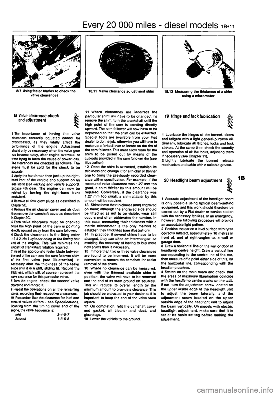
11 Where clearances are incorrect the particular shim will have to be changed. To remove the shim, turn the crankshaft until the high point of the cam is pointing directly upward. The cam follower will now have to bo depressed so that the shim can be extracted. Special tools are available from your Fiat dealer to do the job. otherwise you will have to make up a forked lever to locate on the rim of ihe cam follower. This must allow room for the shim to be prised out by means of the cut-outs provided in the cam follower rim (see illustration). 12 Once Ihe shim is extracted, establish Its thickness and change it for a thicker or thinner one to bring the previously recorded clear-ance within specification, For example, if the measured valve clearance was 1.27 mm too great, a shim thicker by this amount will be required. Conversely, if the clearance was 1.27 mm too small, a shim thinner by this amount will be required. 13 Shims have their thickness (mm) engraved on ihem; although the engraved side should be fitted so as not to be visible, wear still occurs and often obliterates the number. In this case, measuring their thickness with a metric micrometer is the only method to establish their thickness (see illustration). 14 In practice, if several shims have to be changed, they can often be interchanged, so avoiding the necessity of having to buy more new shims than is necessary. 15 If more than two or three valve clearances are found to be incorrect, it will be more convenient to remove the camshaft lor easier removal of the shims. 16 Where no clearance can be measured, even with the Ihinnest available shim in position, the valve will have to be removed and the end of its stem ground off squarely. This will reduce its overall length by the minimum amount to provide a clearance. This job should be entrusted to your dealer as it is important to keep the end of the valve stem square. 17 On completion, refit the camshaft cover and gasket, air cleaner and duct, and glosvplugs. 18 Lower the vehicle to the ground.
19 Hinge and lock lubrication
I
1 Lubricate the hinges of the bonnet, doors and tailgate with a light general-purpose oil. Similarly, lubricate all latches, locks and lock stnkers. At the same time, check the security and operation of all the locks, adjusting them if necessary (see Chapter 11). 2 Lightly lubricate the bonnet release mechanism and cable with a suitable grease.
20 Headlight beam adjustment
I
1 Accurate adjustment of the headlight beam Is only possible using optical beam-setting equipment, and this work should therefore be carried out by a Fiat dealer or service station with the necessary facilities. In an emergency, however, the following procedure will provide an acceptable light pattern. 2 Position the car on a level surface with tyres correctly inflated, approximately 10 metres in front of, and at right-angles to, a wall or garage door. 3 Draw a horizontal tine on the wall or door at headlamp centre height. Draw a vertical line corresponding to the centre line of the car. then measure off a point either side of this, on the horizontal line, corresponding with the headlamp centres. 4 Switch on the main beam and check that the areas of maximum Illumination coincide with the headlamp centre marks on the wall. If not, turn the adjustment screw located on the upper Inside edge of the headlight unit to adjust the beam laterally, and the adjustment screw located on the upper outside edge of the headlight unit to adjust the beam vertically. On models with electric headlight adjustment, make sure that it Is set at its basic setting before making the adjustment,
Page 50 of 225
ib.14 Every 2 years - diesel models
Radiator flushing 7 To flush the radiator disconnect the top and bottom hoses and any other relevant hoses from the radiator, with reference to Chapter 3. 8 Insert a garden hose into the radiator top inlet. Direct a flow of dean water through the radiator, and continue Hushing until clean water emerges from the radiator bottom outlet. 9 II after a reasonable period, the water still does not run clear, the radiator can be flushed with a good proprietary cooling system cleaning agent. It is important that their manufacturer's instructions are followed carefully. If Ihe contamination is particularly bad, insert the hose in the radiator bottom outlet, and reverse-flush the radiator.
Engine flushing 10 To flush tho engine, remove the thermostat as described in Chapter 3. 11 With the bottom hose disconnected, direct a clean flow of water through the engine, and continue Hushing until clean water emerges from the radiator bottom hose. 12 On completion of flushing, refit the thermostat and reconnect the hose with reference to Chapter 3.
Cooling system filling 13 Before attempting to fill the cooling system, make sure that all hoses and clips are in good condition, and that the clips are tight. Note that an antifreeze mixture must be used all year round, to prevent corrosion of the engine components (see following sub* Section). 14 Remove the expansion tank filler cap. and fill the system by slowly pouring the coolant Into Ihe expansion tank to prevent airlocks from forming. Ensure that all bleed plugs/screws are open. 15 If the coolant is being renewed, begin by pouring in a couple of litres of water, followed by the correct quantity of antifreeze, then top* up with more water. 18 Once ihe level in the expansion tank starts to rise, squeeze the radiator top and bottom hoses to help expel any trapped air in
the system. Once all the air is expelled, top-up the coolant level to the MAX mark and refit the expansion tank cap. Close all bleed plugs. 17 Start Ihe engine and run il until it reaches normal operating temperature, then stop the engine and allow It to cool. 18 Check for leaks, particularly around disturbed components. Check the coolant level In the expansion tank, and top-up if necessary. Note that the system must be cold before an accurate level Is indicated In the expansion tank. If the expansion tank cap Is removed while the engine is still warm, cover the cap with a thick cloth, and unscrew the cap slowly to gradually relieve the system pressure (a hissing sound will normally be heard). Wait until any pressure remaining in the system Is released, then continue to turn the cap untH it can be removed.
Antifreeze mixture 19 The antifreeze should always be renewed at the specified intervals. This is necessary not only to maintain the antifreeze properties, but also to prevent corrosion which would otherwise occur as the corrosion Inhibitors become progressively less effective. 20 Always use an ethylene-glycol based antifreeze which is suitable for use in mixed-metal cooling systems. The quantity of antifreeze and levels of protection are indicated in the Specifications. 21 Before adding antifreeze, the cooling system should be complelely drained, preferably flushed, and all hoses checked for condition and security. 22 After filling with antifreeze, a label should be attached to the expansion tank, stating the type and concentration of antifreeze used, and the dale installed. Any subsequent topping-up should bs made with the same type and concentration of antifreeze. 23 Do not use engine antifreeze In the windscreen/tailgate washer system, as it will cause damage to the vehicle paintwork. A screenwash additive should be added to the washer system in the quantities stated on the bottle.
28 Brake fluid renewal
A
Warning: Brake hydraulic fluid can harm your eyas and damage painted surfaces, so use extreme caution when handling and pouring It. Do not use fluid that has been standing open for some time, as It absorbs moisture from the air. Excess moisture can causa a dangerous loss of braking effectiveness. 1 The procedure is similar to that for the bleeding of the hydraulic system as described In Chapter 9. except that the brake fluid reservoir should be emptied by siphoning, using a clean poultry baster or similar before starting, and allowance should be made for the old fluid to be expelled when bleeding a section of the circuit. 2 Working as described in Chapter 9, open Ihe first bleed screw in the sequence, and pump the brake pedal gently until nearly all the old fluid has been emptied from the master cylinder reservoir.
ffffTOgf Old hydraulic fluid Is
lifcjllitt*
Invariably much darker In [HINT] colour than the new, making /{easy to distinguish the two.
3 Top-up to the MAX level with new fluid, and continue pumping until only the new fluid remains in the reservoir, and new fluid can be seen emerging from (he bleed screw. Tighten the screw, and top the reservoir level up to Ihe MAX level line. 4 Work through all the remaining bleed screws In the sequence until new fluid can be seen al all of them. Be careful to keep the master cylinder reservoir topped-up 10 above the MIN level al all limes, or air may enter the system and greatly increase the length of the task. 5 When the operation is complete, check thai all bleed screws are securely tightened, and that their dust caps are refitted. Wash off ail traces of split fluid, and recheck the master cylinder reservoir fluid level. 6 Check the operation of the brakes before taking the car on the road,
Page 149 of 225
5A«2 Starting and charging systems
1 General information and precautions
General information The engine electrical system consists mainly of the charging and starting systems. Because of their engine-related functions, these components are covered separately from the body electrical devices such as the Ilght3, Instalments, etc (which are covered In Chapter 12). On petrol engine models refer to Part B for information on the ignition system, and on diesel models refer to Part C for information on the preheating system. The electncal system Is of 12-volt negative earth type. The battery fitted as original equipment is of maintenance* free (sealed for life} type and Is charged by the alternator, which is belt-driven from the crankshaft pulley. If a non-original battery is fitted It may be of standard or low maintenance type. The starter motor is of the pre-engaged type Incorporating an integral solenoid. On starting, the solenoid moves the drive pinion into engagement with the flywheel ring gear before the starter motor is energised. Once the engine has started, a one-way clutch prevents the motor armature being driven by the engine until the pinion disengages from the flywheel.
Precautions Further details of the various systems are given In the relevant Sections of this Chapter. While some repair procedures are given, the usual course of action is to renew the component concerned. The owner whose interest extends beyond mere component renewal should obtain a copy of the Automobile Electrical & Electronic Systems Manual, available from the publishers of this manual It Is necessary to take extra care when working on the electrical system to avoid damage to semiconductor devices (diodes and transistors), and to avoid the risk of personal injury. In addition to the precautions given in Safety first! at the beginning of this manual, observe the following when working on the system: Always remove rings, watches, etc before working on the electrical system. Even with the battery disconnected, capacitlve discharge could occur If a component's live terminal is earthed through a metal object. This could cause a shock or nasty bum. Do not reverse the battery connections. Components such as the alternator, electronic control units, or any other components having semi-conductor circuitry could be irreparably damaged. If the engine is being started using jump leads and a slave battery, connect the batteries positive-to-posibve and negative-to-
negative (see Jump starting). This also applies when connecting a battery charger but In this case both of the battery terminals should first be disconnected. Never disconnect the battery terminals, the alternator, any electrical wiring or any test Instalments when the engine Is running. Do not allow the engine to turn the alter-nator when the alternator Is not connected. Never test for alternator output by flashing the output lead to earth. Never use an ohmmeter ot the type Incorporating a hand-cranked generator for circuit or continuity testing. Always ensure that the battery negative lead is disconnected when working on the electrical system. Before using electric-arc welding equipment on the car, disconnect the battery, alternator and components such as the fuel Injection/ignition electronic control unit to protect them from the risk of damage. Several systems fitted to the vehicle require battery power to be available at all times, either to ensure their continued operation (such as the clock) or to maintain control unit memories or security codos which would be wiped if the battery were to be disconnected. To ensure that there are no unforeseen consequences of this action. Refer to Disconnecting the battery In the Reference Section of this manual for further Information.
2 Battery- % testing and charging
Standard and tow maintenance battery - testing 1 If the vehicle covers a small annual mileage, it is worthwhile checking the specific gravity of the electrolyte every three months to determine the state of charge of the battery. Use a hydrometer to make the check and compare the results with the following table, Note that the specific gravity readings assume an electrolyte temperature of 15*C (60'F); for every 10*C (18°f) below 158C (60aF) subtract 0.007, For every 108C (16'F) above 15"C (60'F) add 0.007. Ambient temperature Above 26"C Below 25DC Charged 1,210 to 1£30 1,270 to 1.290 70% charged 1.170to1.l90 1.230to1.250 Discharged 1.050toJ.070 1.110 to 1.130 2 If the battery condition is suspect, first check the specific gravity of electrolyte In each cell. A variation of 0.040 or more between any cells indicates loss of electrolyte or deterioration of the internal plates. 3 If the specific gravity variation is 0.040 or more, the battery should be renewed. If the cell variation Is satisfactory but the battery is discharged, it should be charged as described later in this Section.
Maintenance-free battery -testing 4 In cases where a sealed tor life maintenance-free battery is fitted, topplng-up and testing of the electrolyte in each cell Is not possible. The condition of the battery can therefore only be tested using a battery condition Indicator or a voltmeter. 5 Certain models may be fitted with a maintenance-free battery with a built-in charge condition Indicator. The indicator Is located in the top of the battery casing, and indicates the condition of the battery from its colour. If the Indicator shows green, then the battery is In a good state of charge. If the Indicator turns darker, eventually to black, then the battery requires charging, as described later in this Section. If Ihe indicator shows clear/yellow, then the electrolyte level in Ihe battery is too low to allow further use, and tho battery should be renewed. Do not attempt to charge, load or Jump start a battery when the indicator shows dear/yellow. 6 If testing the battery using a voltmeter, connect the voltmeter across the battery and compare the result with those given In the Specifications under 'charge condition'. The test is only accurate if the battery has not been subjected to any kind of charge for the previous six hours. If this is not the esse, switch on the headlights for 30 seconds, then wait four to five minutes baforo testing the battery after switching off the headlights. All other electrical circuits must be switched off, so check that the doors and tailgate are fully shut when making the test, 7 It the voltage reading Is less than 12.2 voHs, then the battery Is discharged, whilst a reading of 12.2 to 12.4 volts indicates 8 partially discharged condition. 6 If the battery Is to be charged, remove It from the vehicle (Section 3) and charge it as described later In this Section.
Standard and low maintenance battery - charging Note: The following is Intended as a guide only. Always refer to the manufacturer's recommendations (often printed on a label attached to the battery) before charging a battery. 9 Charge the battery at a rate of 3.5 to 4 amps and continue to charge the battery at this rate until no further rise In specific gravity Is noted over a four hour period. 10 Alternatively, a trickle charger charging at the rate of 1.5 amps can safely be used overnight. 11 Specially rapid boost charges which are claimed to restore the power of the battery in t to 2 hours are not recommended, as they can cause serious damage to the battery plates through overheating, 12 While charging the battery, note that the temperature of the electrolyte should never exceed 37.8*C(100°F),
Page 202 of 225
10*1
Chapter 11
Bodywork and fittings
Contents
Bonnet • removal and refitting 11 Bonnet lock components - removal and refitting 12 Bonnet release cable - removal and refitting 13 Door - removal and refitting 15 Door handle and lock components • removal and refitting 16 Door inner trim panel • removal and refitting 14 Electric window components • removal and refitting 18 Exterior mirror components - removal and refitting 17 Facia - removal and refitting 19 Front bumper • removal and refitting 6
General Information 1 Maintenance - bodywork and underframe 2 Maintenance - upholstery and carpets 3 Major body damage - repair 5 Minor body damage - repair 4 Rear bumper - removal and refitting 7 Seats • removal and refitting 20 Tailgate - removal and refitting 8 Tailgate lock components - removal and refitting 10 Tailgate strut - removal and refitting 9
Degrees of difficulty
Easy, suitable for
novice with littie experience ^
Fairly
easy,
suitable ^ for beginner with ^
some
experience
Fairty difficult,
^
suitable
fcr competent
DIY
mechanic ^
Difficult,
suitable (or
^ experienced DIY »R mechanic ^
Very difficult,
^
suitable
for
expert CHY
or professional ^
Specifications
! Torque wrench settings Nm ibf ft Bonnet-to-hinge botts 8 6 Door hinge-to-body bolts 35 26
1 Genera! information
The bodyshell is composed of pressed-steel sections which are welded together, although some use of structural adhesives is made. In addition, the front wings are bolted i on. ' The bonnet, door and some other panels I vulnerable to corrosion are fabricated from zinc-coated metal. A coating of anti-chip primer, applied prior to paint spraying I provides further protection. Extensive use is made of plastic materials. ' mainly In the Interior, but also in exterior components. The outer sections of the front l and rear bumpers are injection-moulded from
a
synthetic material which is very strong, and yet light. Plastic components such as wheel | arch liners are fitted to the underside of the vehicle, to improve Ihe body's resistance to I corrosion.
2 Maintenance - ^ bodywork and underframe ||
The general condition of a vehicle's bodywork is the one thing that significantly affects its value. Maintenance is easy, but needs to be regular. Neglect, particularly after minor damage, can lead quickly to further deterioration and costly repair bills. It is important also to keep watch on those parts of the vehicle not immediately visible, for instance the underside, inside all the wheel arches, and the lower part of the engine compartment. The basic maintenance routine for the bodywork is washing - preferably with a lot of water, from a hose. This will remove all the loose solids which may have stuck to the vehicle. It is important to flush these off in such a way as to prevent grit from scratching the finish. The wheel arches and underframe need washing in the same way, to remove any
accumulated mud. which will retain moisture and tend to encourage rust. Paradoxically enough, the best time to clean the underframe and wheel arches is in wet weather, when the mud is thoroughly wet and soft. In very wet weather, the underframe is usually cleaned of large accumulations automatically, and this is a good time for inspection. Periodically, except on vehicles with a wax-based underbody protective coating, it is a good idea to have the whole of the underframe of Ihe vehicle steam-cleaned, engine compartment included, so that a thorough inspection can be carried out to see what minor repairs and renovations are necessary. Steam-cleaning is available at many garages, and is necessary for the removal of the accumulation of oily grime, which sometimes is allowed to become thick In certain areas. If steam-cleaning facilities are
Page 206 of 225
Bodywork and fittings
11
*5
8.2 Release the fixings and lower the trim panel away from the tailgate
Refitting 7 The pumper is refitted by following the removal procedure In reverse.
8 Tailgate- ^ removal and refitting
Removal 1 Disconnect the battery negative tormina) {refer to D/sconnecf/ng the battery In the Reference Section of this manual}. 2 Release the press stud fixings and extract ihe screws, then lower the trim panel away from the tailgate (see illustration). 3 Working inside the tailgate, disconnect all wiring harness connectors and unbolt the earth leads. Check for any other wiring connectors which must be disconnected to facilitate tailgate removal. Note: Carefully label each wiring harness connector (o aid correct refitting. 4 Tie a length of cord to the wiring harness, then bind the loose ends of the cabling together using PVC tape. Prise the winng harness grommets from the upper edge of the tailgate, then feed the wiring through the aperture in the tailgate. Untie the cord from the harness, but leave it In place In the tailgate, to aid refitting later. 5 Where applicable, remove the fluid hose from the tailgate washer nozzle, as described in Chapter 12. Section 16. then tie a length of
8.2a Lever off the balljoint spring clip...
8.8 Slacken and unscrew the bolts (arrowed) securing the hinges to the tailgate
cord to the hose and draw it out of the tailgate, using the same procedure carried out on the wiring harness. 8 Have an assistant support the tailgate in the open position. 7 Detach the upper ends of the support stmts from the tailgate as described in Section 9. 8 Slacken and unscrew the bolts securing tho hinges to the tailgate (seo illustration), then lift the tailgate from the vehicle.
Refitting 9 Refitting is a reversal of removal, bearing in mind the following points. a) Tie the cord to the wiring harness and use It to pull the harness through the aperture and into the tailgate. Where applicable, repeat the procedure on the washer fluid hose. b) Do not fully tighten the hinge bolts until the tailgate adjustment has been checAed, as described in the following paragraphs.
Adjustment 10 Close the tailgate carefully, in case the alignment is Incorrect, which may cause scratching on the tailgate or the body as the tailgate is closed, and check for alignment with the adjacent panels. If necessary, slacken the bolts that secure the hinges to the bodywork and re-align the tailgate to suit. Once the tailgate is correctly aligned, tighten the hinge bolts securely.
9.2b ... and then prise strut balljoint from the stud on tho taitgate
11 Check that the tailgate fastens and releases In a satisfactory manner. If adjustment Is necessary, slacken the striker plate retaining bolts, and adjust the position of the lock to suit (see Section 10). Once the lock is operating correctly, securely tighten the striker plate retaining bolts. 12 If necessary, adjust the protrusion of the rubber buffers at the lower edge of the tailgate, by screwing them in or out as appropriate.
9 Tailgate strut - ^ removal and refitting
Removal 1 Open the tailgate and support it using suitable wooden props. 2 At the upper end of each strut, lever off the balljoint spring clip. Compress tho strut slightly by hand and then prise strut balljoint from the stud on the tailgate (see illustrations),
A
Warning: The strut may still be under tension and could extend suddenly once detached from Its mountings. 3 At the lower end of the strut, unbolt the joint Irom the bodywork. Refitting 4 Refitting is a reversal of removal.
10 Tailgate lock components -removal and refitting ^
Lock and cylinder assembly Removal 1 With the tailgate held In the fully open position, slacken and unscrew the bolts securing the lock assembly to tho lower edge of tho tailgate (soo illustration). 2 Carefully withdraw the lock assembly, together with tne lock cylinder (see Illustration).
10.1 Unscrew the bolts (arrowed) securing the lock assembly to the lower edge of the tailgate
Page 207 of 225
11
*6 Bodywork and fittings
10.3c ... and lift off die lock cylinder
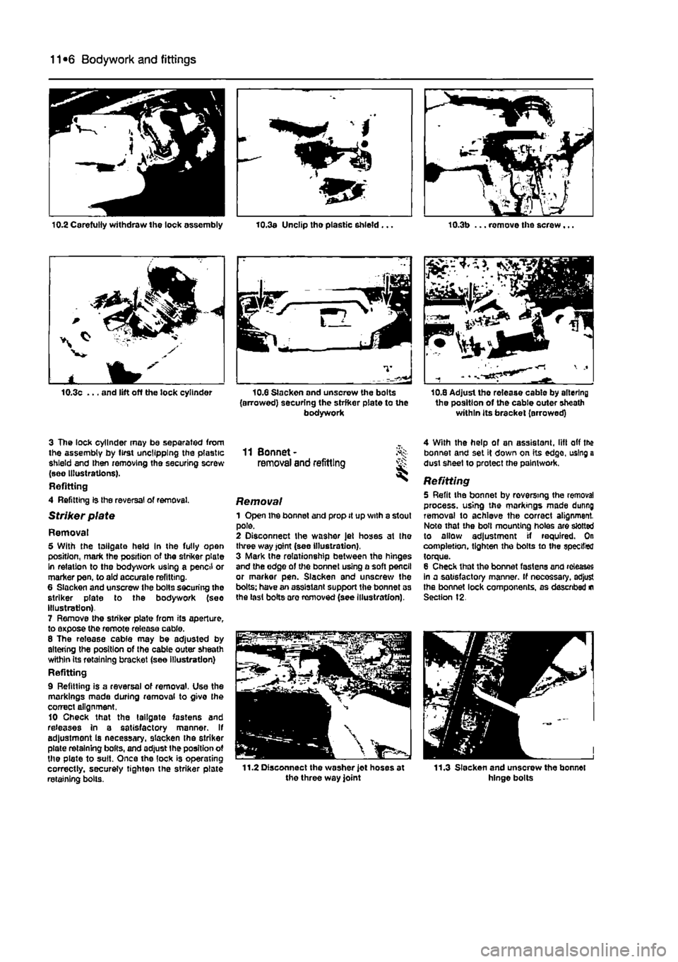
3 The lock cylinder may be separated from the assembly by first uncllpplng the plastic shield and then removing the securing screw (see Illustrations). Refitting 4 Refitting is Ihe reversal of removal.
Striker plate
Removal 5 With the tailgate held In the fully open position, mark the position of the striker plate In relation to the bodywork using a pencil or marker pen, to aid accurate refitting. 6 Slacken and unscrew the bolts securing the striker plate to the bodywork (see Illustration) 7 Remove the striker plate from its aperture, to expose the remote release cable. 8 The release cable may be adjusted by altering the position of Ihe cable outer sheath wKhin its retaining bracket (see illustration) Refitting 9 Refitting is a reversal of removal. Use the markings made during removal to givo Ihe correct alignment. 10 Check that the tailgate fastens and releases in a satisfactory manner. If adjustment Is necessary, slacken the striker plate retaining bolts, and adjust Ihe position ot the plate to suit. Once the lock is operating correctly, securely tighten the striker plate retaining bolls.
10.3a Unclip tho plastic shield... 10.3b ... remove the screw...
10.8 Slackon and unsorew the bolts (arrowed) securing the strfker plate to the bodywork
Si
10,8 Adjust the rolease cable by altering the position of the cable outer sheath within its bracket (arrowed)
11 Bonnet-removal and refitting
Removal 1 Open the bonnet and prop it up with a stout pole. 2 Disconnect the washer Jet hoses at the three way joint (see illustration), 3 Mark the relationship between the hinges and the edge of the bonnet using a soft pencil or markor pen. Slacken and unscrew the bolts: have an assistant support the bonnet as the last bolts aro removed (see Illustration),
4 With the help of an assistant, lift off the bonnet and set it down on its edge, using a dust sheet to protect the paintwork.
Refitting 5 Refit the bonnet by reversing the removal process, using the markings made dunng removal to achieve the correct alignment. Note that the boll mounting holes are slotted to allow adjustment if required. On completion, tighten the bolts to the specified torque. 8 Check that the bonnet fastens and releases in a satisfactory manner. If necessary, adjust the bonnet lock components, as described
m
Section 12.
Page 214 of 225
10*1
Chapter 12
Body electrical systems
Contents
Bulbs (exterior lights) - renewal 4 Bulbs (interior lights) - renewal 5 Electrical fault finding - general information 2 Exterior light units - removal and refitting 6 Fuses and relays - general Information 3 General information and precautions 1 Headlight beam alignment • general Information 6 Horn • removal and refitting 9 Instrument panel - removal and refitting 7 Loudspeakers - removal and refitting 10
Degrees of difficulty
Radio aerial - removal and refitting 11 Radio/cassette player • removal and refitting 12 Speedometer drive cable - removal and refitting 13 Switches - removal end refitting 14 Tailgate wiper motor - removal and refitting 15 Windscreen wiper motor - removal and refitting 17 Windscreen/tailgate washer system components • removal and refitting 16 Wiper arm • removal and refitting 18
Easy,
statable for ^
novice with liffle
|| experience ^
Fairly
easy,
suitable for beginner with ^ some experience ^
Fabtycffficiit,
suitable
for competent ^
DIY
mechanic ^
Difficult, suitable for
^ experienced DIY JR mechanic
Very difficult,
A,
suitable
for
expert DIY
Sj or professional ^
Specifications
Bulb ratings Watts Headlights 60/55 Front long range driving light 55 Front fogllght 55 Front direction Indicator light 21 Front sidelight 5 Front direction indicator repeater light 5 Stop light 21 Tall light 5 Rear direction indicator light 21 Reversing light 21 near fogllght 21 Hear number plate light 5 Courtesy light 10 Map reading light 5
1 Genera! information and precautions
A
Warning: fie/Ore carrying out any work on the electrical system, read through the precautions given in Safety first! at the beginning of this manual, and in Chapter 8. The electrical system is of 12-volt negative earth type. Power for the lights and all electrical accessories is supplied by a lead/acid type battery, which is charged by the alternator. This Chapter covers repair and service procedures for the various electrical components not associated with the engine. Information on the battery, alternator and starter motor can be found in Chapter 5. It should be noted that, prior to working on any component In the electrical system, the
battery negative terminal should first be disconnected, to prevent the possibility of electrical short-circuits and/or fires. Caution: Before proceeding, refer to Disconnecting the battery In the Reference Section of this manual for further information.
2 Electrical fault finding-general information
Note: Refer to the precautions given In Safety first! and in Section 1 of this Chapter before starting work. The following tests relate to testing ot the main electrical circuits, and should not be used to test delicate electronic circuits (such as antHock braking systems), particularly where an electronic con fro/ module is used.
General 1 A typical electrical circuit consists of an electrical component, any switches, relays, motors, fuses, fusible links or circuit breakers related to that component, and the wiring and connectors which link the component to both the battery and the chassis. To help to pinpoint a problem in an electrical circuit, wiring diagrams are Included at the end of this manual. 2 Before attempting to diagnose an electrical fault, first study the appropriate wiring diagram, to obtain a more complete understanding of the components included In the particular circuit concerned. The possible sources of a fault can be narrowed down by noting whether other components related to the circuit are operating properly. If several components or circuits fait at one time, the problem Is likely to be related to a shared fuse or earth connection.