washer fluid FIAT PUNTO 1998 176 / 1.G User Guide
[x] Cancel search | Manufacturer: FIAT, Model Year: 1998, Model line: PUNTO, Model: FIAT PUNTO 1998 176 / 1.GPages: 225, PDF Size: 18.54 MB
Page 50 of 225
ib.14 Every 2 years - diesel models
Radiator flushing 7 To flush the radiator disconnect the top and bottom hoses and any other relevant hoses from the radiator, with reference to Chapter 3. 8 Insert a garden hose into the radiator top inlet. Direct a flow of dean water through the radiator, and continue Hushing until clean water emerges from the radiator bottom outlet. 9 II after a reasonable period, the water still does not run clear, the radiator can be flushed with a good proprietary cooling system cleaning agent. It is important that their manufacturer's instructions are followed carefully. If Ihe contamination is particularly bad, insert the hose in the radiator bottom outlet, and reverse-flush the radiator.
Engine flushing 10 To flush tho engine, remove the thermostat as described in Chapter 3. 11 With the bottom hose disconnected, direct a clean flow of water through the engine, and continue Hushing until clean water emerges from the radiator bottom hose. 12 On completion of flushing, refit the thermostat and reconnect the hose with reference to Chapter 3.
Cooling system filling 13 Before attempting to fill the cooling system, make sure that all hoses and clips are in good condition, and that the clips are tight. Note that an antifreeze mixture must be used all year round, to prevent corrosion of the engine components (see following sub* Section). 14 Remove the expansion tank filler cap. and fill the system by slowly pouring the coolant Into Ihe expansion tank to prevent airlocks from forming. Ensure that all bleed plugs/screws are open. 15 If the coolant is being renewed, begin by pouring in a couple of litres of water, followed by the correct quantity of antifreeze, then top* up with more water. 18 Once ihe level in the expansion tank starts to rise, squeeze the radiator top and bottom hoses to help expel any trapped air in
the system. Once all the air is expelled, top-up the coolant level to the MAX mark and refit the expansion tank cap. Close all bleed plugs. 17 Start Ihe engine and run il until it reaches normal operating temperature, then stop the engine and allow It to cool. 18 Check for leaks, particularly around disturbed components. Check the coolant level In the expansion tank, and top-up if necessary. Note that the system must be cold before an accurate level Is indicated In the expansion tank. If the expansion tank cap Is removed while the engine is still warm, cover the cap with a thick cloth, and unscrew the cap slowly to gradually relieve the system pressure (a hissing sound will normally be heard). Wait until any pressure remaining in the system Is released, then continue to turn the cap untH it can be removed.
Antifreeze mixture 19 The antifreeze should always be renewed at the specified intervals. This is necessary not only to maintain the antifreeze properties, but also to prevent corrosion which would otherwise occur as the corrosion Inhibitors become progressively less effective. 20 Always use an ethylene-glycol based antifreeze which is suitable for use in mixed-metal cooling systems. The quantity of antifreeze and levels of protection are indicated in the Specifications. 21 Before adding antifreeze, the cooling system should be complelely drained, preferably flushed, and all hoses checked for condition and security. 22 After filling with antifreeze, a label should be attached to the expansion tank, stating the type and concentration of antifreeze used, and the dale installed. Any subsequent topping-up should bs made with the same type and concentration of antifreeze. 23 Do not use engine antifreeze In the windscreen/tailgate washer system, as it will cause damage to the vehicle paintwork. A screenwash additive should be added to the washer system in the quantities stated on the bottle.
28 Brake fluid renewal
A
Warning: Brake hydraulic fluid can harm your eyas and damage painted surfaces, so use extreme caution when handling and pouring It. Do not use fluid that has been standing open for some time, as It absorbs moisture from the air. Excess moisture can causa a dangerous loss of braking effectiveness. 1 The procedure is similar to that for the bleeding of the hydraulic system as described In Chapter 9. except that the brake fluid reservoir should be emptied by siphoning, using a clean poultry baster or similar before starting, and allowance should be made for the old fluid to be expelled when bleeding a section of the circuit. 2 Working as described in Chapter 9, open Ihe first bleed screw in the sequence, and pump the brake pedal gently until nearly all the old fluid has been emptied from the master cylinder reservoir.
ffffTOgf Old hydraulic fluid Is
lifcjllitt*
Invariably much darker In [HINT] colour than the new, making /{easy to distinguish the two.
3 Top-up to the MAX level with new fluid, and continue pumping until only the new fluid remains in the reservoir, and new fluid can be seen emerging from (he bleed screw. Tighten the screw, and top the reservoir level up to Ihe MAX level line. 4 Work through all the remaining bleed screws In the sequence until new fluid can be seen al all of them. Be careful to keep the master cylinder reservoir topped-up 10 above the MIN level al all limes, or air may enter the system and greatly increase the length of the task. 5 When the operation is complete, check thai all bleed screws are securely tightened, and that their dust caps are refitted. Wash off ail traces of split fluid, and recheck the master cylinder reservoir fluid level. 6 Check the operation of the brakes before taking the car on the road,
Page 92 of 225
2D*10 Engine removal and overhaul procedures
Engine and transmission -removal, separation, connection and refitting
Note: The engine Is lowered from the engine compartment as a complete unit with the transmission; tho two are then separated for overhaul.
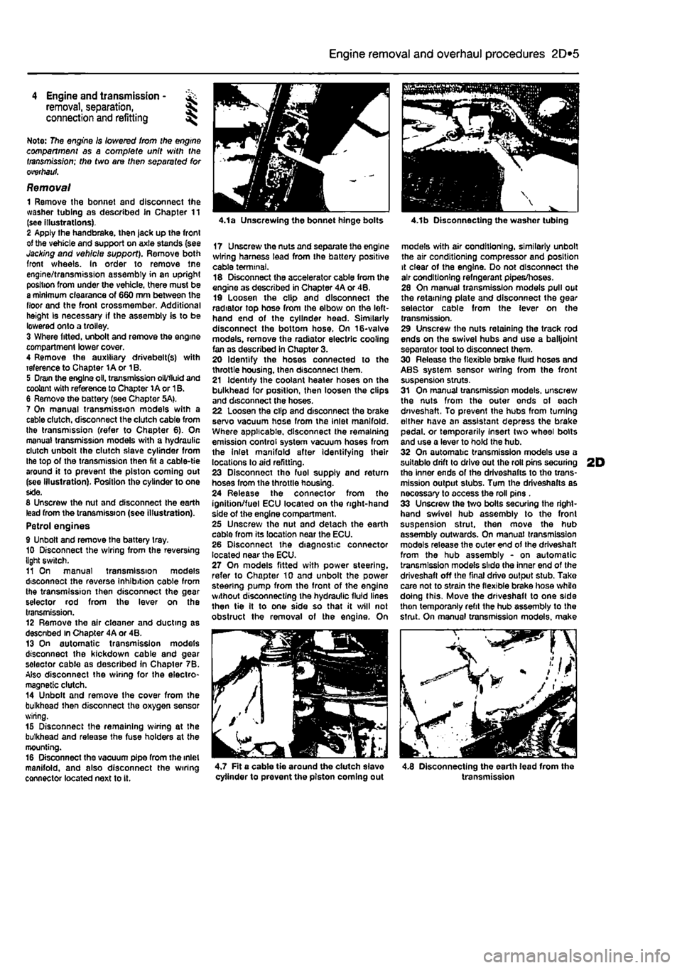
Removal 1 Remove the bonnet and disconnect the washer tubing as described in Chapter 11 (see illustrations). 2 Apply the handbrake, then jack up the front of the vehicle and support on axle stands (see Jacking and vehicle support). Remove both front wheels. In order to remove tne engine/transmission assembly in an upright position from under the vehicle, there must be a minimum clearance of 660 mm between the floor and the front crossmember. Additional height Is necessary if the assembly is to be lowered onto a trolley. 3 Where fitted, unbolt and remove the engine compartment lower cover. 4 Remove the auxiliary drivebelt(s) with reference to Chapter 1A or 1B. 5 Dram the engine oil. transmission oil/fluid and coolant with reference to Chapter 1A or 1B. 6 Remove the battery (see Chapter 5A). 7 On manual transmission models with a cable dutch, disconnect the clutch cable from the transmission (refer to Chapter 6). On manual transmission models with a hydraulic clutch unbolt the clutch slave cylinder from the top of the transmission then fit a cable-tie around it to prevent the piston coming out (see Illustration). Position the cylinder to one side. 8 Unscrew the nut and disconnect the earth lead from the transmission (see illustration). Petrol engines 9 Unbolt and remove the battery tray. 10 Disconnect the wiring from the reversing light switch. 11 On manual transmission models disconnect the reverse Inhibition cable from the transmission then disconnect the gear selector rod from the lever on the transmission. 12 Remove the air cleaner and ducting as descnbed In Chapter 4A or 4B. 13 On automatic transmission models disconnect the kickdown cable and gear selector cable as described in Chapter 7B. Also disconnect the wiring for the electro-magnetic clutch. 14 Unbolt and remove the cover from the bulkhead then disconnect the oxygen sensor wiring. 15 Disconnect the remaining wiring at the bulkhead and release the fuse holders at the mounting. 16 Disconnect the vacuum pipe from the inlet manifold, and also disconnect the wiring connector located next to it.
4.1a Unscrewing the bonnet hinge bolts
17 Unscrewthenutsandseparatetheengine wiring harness lead from the battery positive cable terminal. 18 Disconnect the accelerator cable from the engine as described in Chapter 4A or 4B, 19 Loosen the clip and disconnect the radiator top hose from the elbow on the left-hand end of the cylinder head. Similarly disconnect the bottom hose. On 16-valve models, remove the radiator electric cooling fan as described in Chapter 3. 20 Identify the hoses connected to the throttle housing, then disconnect them. 21 Identify the coolant heater hoses on the bulkhead for position, then loosen the clips and disconnect the hoses. 22 Loosen the clip and disconnect the brake servo vacuum hose from the Inlet manifold. Where applicable, disconnect the remaining emission control system vacuum hoses from the Inlet manifold after Identifying their locations to aid refitting. 23 Disconnect tho fuel supply and return hoses from the throttle housing. 24 Release the connector from the ignition/fuel ECU located on the right-hand side of the engine compartment. 25 Unscrew the nut and detach the earth cable from its location near the ECU. 26 Disconnect the diagnostic connector located near the ECU. 27 On models fitted with power steering, refer to Chapter 10 and unbolt the power steering pump from the front of the engine without disconnecting the hydraulic fluid lines then tie It to one side so that it will not obstruct the removal of the engine. On
4.1b Disconnecting the washer tubing
models with air conditioning, similarly unbolt the air conditioning compressor and position it clear of the engine. Do not disconnect the air conditioning refngerant pipes/hoses. 26 On manual transmission models pull out the retaining plate and disconnect the gear selector cable from the lever on the transmission. 29 Unscrew the nuts retaining the track rod ends on the swivel hubs and use a balljoint separator tool to disconnect them. 30 Release the flexible brake fluid hoses and ABS system sensor wrring from the front suspension struts. 31 On manual transmission models, unscrew the nuts from the outer ends of each driveshaft. To prevent the hubs from turning either have an assistant depress the brake pedal, or temporarily Insert two wheel bolts and use a lever to hold the hub. 32 On automatic transmission models use a suitable drift to drive out Ihe roll pins securing 2D the inner ends of the drlveshafts to tho trans-mission output stubs. Turn the driveshalts as necossary to access the roll pins . 33 Unscrew the two bolts securing the right-hand swivel hub assembly to the front suspension strut, then move the hub assembly outwards. On manual transmission models release the outer end of the driveshaft from the hub assembly - on automatic transmission models slide the inner end of the driveshaft off the final drive output stub. Take care not to strain the flexible brake hose while doing this. Move the driveshaft to one side thon temporanly refit the hub assembly to the strut. On manual transmission models, make
^ - / //
4.7 Fit a cable tie around the dutch slave cylinder to prevent the piston coming out 4.8 Disconnecting the earth lead from the transmission
Page 160 of 225
Clutch 6*3
6 WorWng inside the vehicle, extract the split pin and remove the washer securing the master cylinder pushrod to the clutch pedal. Dsoonnect the pushrod from the pivot. 7 Have an assistant support the master cylinder In the engine compartment, then unscrew the mounting bolts. Withdraw the master cylinder from the engine compartment, 8 II is not possible to obtain an overhaul kit from Flat however some motor factors may be abls to supply one. Follow the Instructions with the repair kit if obtained.
Refitting 9 Refit the clutch master cylinder by following ihe removal procedure In reverse, noting the following. a) Apply a
Utile
high-melting point grease to the clutch pedal pivot. b) Tighten the mounting bolts and union nut securely. cj Fit a new split pin to the pushrod. d) Where removed, refit the alternator
as
described In Chapter 5A e) On completion bleed the clutch hydraulic system as descnbed in Section
A.
7 Clutch assembly -
removal,
inspection
and
refitting
S Clutch slave cylinder-removal and refitting
Note: This procedure applies to models fitted
ivrth
the hydraulically-operated clutch release mechanism. Note: Refer to the warning at the beginning
of
Section A regarding the hazards of working
with
hydraulic fluid.
Removal 1 Remove the battery and battery tray as described in Chapter 5A. 2 Fit a brake hose clamp to tha hose leading to the clutch slave cylinder. 3 Unscrew the union nut and disconnect the hydraulic pipe from the slave cylinder. Be prepared for some fluid loss by placing rags beneath the cylinder. 4 Unscrew the mounting bolts and release the slave cylinder pushrod from the release am on the transmission, then remove the unit from the engine compartment (see Illustration). 5 It is not possible to obtain an overhaul kit from Flat however some motor factors may be able to supply one. Follow tha instructions with the repair kit if obtained.
Refitting 6 Refit the clutch slave cylinder by following the removal procedure In reverse, noting the following. a) Apply a little high-melting point grease to the tip of the slave cylinder pushrod. b) Tighten the mounting bolts and union nut securely. c) On completion bleed the dutch hydraulic system as described in Section A.
A
Warning: Dust created by clutch wear and deposited on the clutch components may contain asbestos, which Is a health hazard. DO NOT blow it out with compressed air, or inhale any of it. DO NOT use petrol or petroleum-based solvents to clean off the dust. Brake system cleaner or methylated spirit should be used to flush the dust Into a suitable receptacle. After the clutch components are wiped clean with rags, dispose of the confam/nafed rags and cleaner In a sealed, marked container. Note: Although some friction materials may no longer contain asbestos, it is safest to assume that they DO. and to take precautions accordingly.
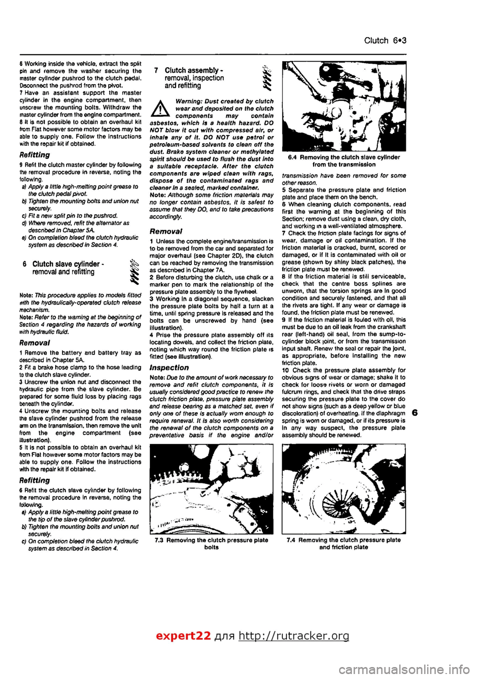
Removal 1 Unless the complete engine/transmission is to be removed from the car and separated for major overhaul (see Chapter 2D), Ihe clutch can be reached by removing the transmission as descnbed in Chapter 7A, 2 Before disturbing the clutch, use chalk or a marker pen to mark the relationship of the pressure plate assembly to the flywheel. 3 Working In a diagonal sequence, slacken the pressure plate bolts by half a turn at a time, until spring pressure Is released and the bolls can be unscrewed by hand (see Illustration). 4 Prise the pressure piate assembly off its locating dowels, and collect the friction plate, noting which way round the friction plate is fitted (see Illustration).
Inspection Note: Due to the amount of work necessary to remove and refit clutch components, It is usually considered good practice to renew the clutch friction plate, pressure plate assembly and release bearing as a matched set. even if only one of these is actually worn enough to require renewal. It Is also worth considering the renewal of the clutch components on a preventative basis if the engine and/or
6.4 Removing the clutch slave cylinder from the transmission fransmj'ss/on have been removed for some other reason. 5 Separate the pressure plate and friction plate and place them on the bench. 6 When cleaning clutch components, read first the warning at the beginning of this Section; remove dust using a clean, dry cloth, and working in a well-ventilated atmosphere. 7 Check the friction plats facings for signs Of wear, damage or oil contamination. If the friction material is cracked, burnt, scored or damaged, or if It is contaminated with oil or grease (shown by shiny black patches), the friction plate must be renewed. 8 If tho friction material Is still serviceable, check that the centre boss splines are unworn, that the torsion springs are In good condition and securely fastened, and that all the rivets are tight. If any wear or damage is found, the friction plate must be renewed. 9 If the friction material is fouled with oil, this must be duo to an oil leak from the crankshaft rear (left-hand) oil seal, from the sump-to-cytinder block joint, or from the transmission Input shaft. Renew tha soal or repair the Joint, as appropriate, before Installing the new friction plate. 10 Check tha pressure plate assembly for obvious signs of wear or damage; shake it to check for looss rivets or worn or damaged fulcrum rings, and check thai the drive straps securing the pressure plate to the cover do not show signs (such as a deep yellow or blue discoloration) of overheating. If the diaphragm spring is worn or damaged, or if its pressure is In any way suspect, the pressure plate assembly should be renewed.
7.3 Removing the clutch pressure plate bolts 7.4 Removing the clutch pressure plate and friction plate
expert22 {
a http://rutracker.org
Page 181 of 225
Braking system 9®5
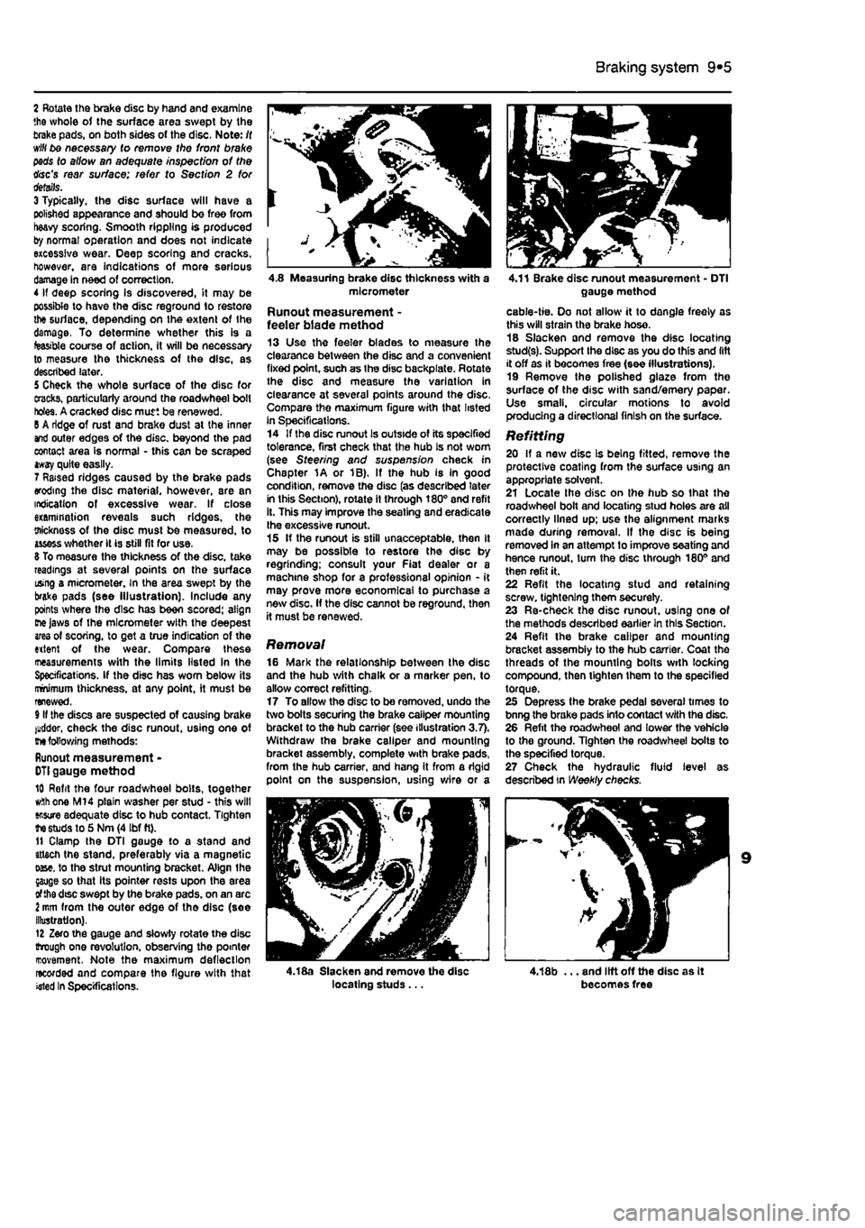
2 Rotate the brake disc by hand and examine the whole of the surface area swept by the brake pads, on both sides ot the disc. Note: /( will bo necessary to remove the front brake pads to allow an adequate inspection of the disc's rear surface; refer to Section 2 tor details. 3 Typically, the disc surface will have a polished appearance and should be free from heavy scoring. Smooth rippling is produced by normal operation and does not indicate excessive wear. Deep scoring and cracks, however, are indications of more serious damage in need of correction. 4 If deep scoring Is discovered, it may be possible to have the disc reground to restore the surface, depending on the extent of the damage. To determine whether this is a feasible course of action, it will be necessary to measure the thickness of the disc, as described later. 5 Check the whole surface of the disc for cracks, particularly around the roadwheel bolt holes. A cracked disc mutt be renewed. 6 A ridge of rust and brake dust at the inner and outer edges of the disc, beyond the pad contact area is normal - this can be scraped tway quite easily. 7 Raised ridges caused by the brake pads eroding the disc material, however, are an indication of excessive wear. If close examination reveals such ridges, the oiicknoss of the disc must be measured, to usess whether it is still fit for use. 8 To measure the thickness of the disc, take readings at several points on the surface using a micrometer. In the area swept by the brake pads (see Illustration). Include any points where the disc has been scored: align me Jaws of the micrometer with the deepest ares of scoring, to get a true indication of the extent of the wear. Compare these ineasurements with the limits listed in the Specifications. If the disc has worn below its minimum thickness, at any point, it must be renewed. 9 If the discs are suspected of causing brake luddor, check the disc runout, using one of
me
following methods: Runout measurement -
DTI
gauge method 10 Refit the four roadwheel bolts, together
w.1h
one M14 plain washer per stud • this will ensure adequate disc to hub contact. Tighten te studs to 5 Nm (4 Ibf ft). 11 Clamp the DTI gauge to a stand and attach the stand, preferably via a magnetic oase. to the strut mounting bracket. Align the jauge so that its pointer rests upon the area of the dtsc swept by the brake pads, on an arc i mm from the outer edge of tho disc (soe illustration). 12 Zero the gauge and slowly rotate the disc trough one revolution, observing tho pointer rcovement. Note the maximum deflection recorded and compare the figure with that >«ted In Specifications.
4.8 Measuring brake disc thickness with a micrometer
Runout measurement -feeler blade method 13 Use the feeler blades to measure the clearance between the disc and a convenient fixed point, such as the disc backplate. Rotate the disc and measure the variation in clearance at several points around the disc, Compare the maximum figure with that listed in Specifications. 14 If the disc runout Is outside of its specified tolerance, first check that the hub Is not worn (see Steering and suspension check in Chapter 1A or 1B). If the hub is In good condition, remove the disc (as described later in this Section), rotate it through 180° and refit it. This may improve the seating and eradicate Ihe excessive runout. 15 If the runout is still unacceptable, then It may be possible to restore the disc by regrinding; consult your Fiat dealer or a machine shop for a professional opinion - it may prove more economical to purchase a new disc. If the disc cannot be reground, then it must be renewed.
Removal 16 Mark the relationship between the disc and the hub with chalk or a marker pen, to allow correct refitting. 17 To allow the disc to be removed, undo the two bolts securing (he brake caliper mounting bracket to the hub carrier (see illustration 3.7). Withdraw the brake caliper and mounting bracket assembly, complete with brake pads, from the hub carrier, and hang it from a rigid point on the suspension, using v/lre or a
4.18a Slacken and remove the disc locating studs ...
4.11 Brake disc runout measurement - DTI gauge method
cable-tie. Oo not allow it to dangle freely as this will strain the brake hose. 18 Slacken and remove the disc locating stud(s). Support the disc as you do this and lift it off as it becomes free (see illustrations). 19 Remove the polished glaze from the surface of the disc with sand/emery paper. Use small, circular motions to avoid producing a directional finish on the surface.
Refitting 20 If a new disc Is being fitted, remove the protective coating from the surface U9ing an appropriate solvent. 21 Locate Ihe disc on ihe hub so that the roadwheel bolt and locating stud holes are all correctly lined up; use the alignment marks made during removal. If the disc is being removed in an attempt to improve seating and hence runout, turn the disc through 180° and then refit it. 22 Refit the locating stud and retaining screw, tightening them securely. 23 Re-check the disc runout, using one of the methods described earlier in this Section. 24 Refil the brake caliper and mounting bracket assembly to the hub carrier. Coat the threads of the mounting bolts with locking compound, then tighten them to the specified torque. 25 Depress the brake pedal several times to bnng the brake pads into contact with the disc. 26 Refit the roadwheel and lower the vehicle to the ground. Tighten the roadwheel bolts to the specified torque. 27 Check the hydraulic fluid level as described in Weekly checks.
4,18b ... and lift off the disc as It becomes free
Page 189 of 225
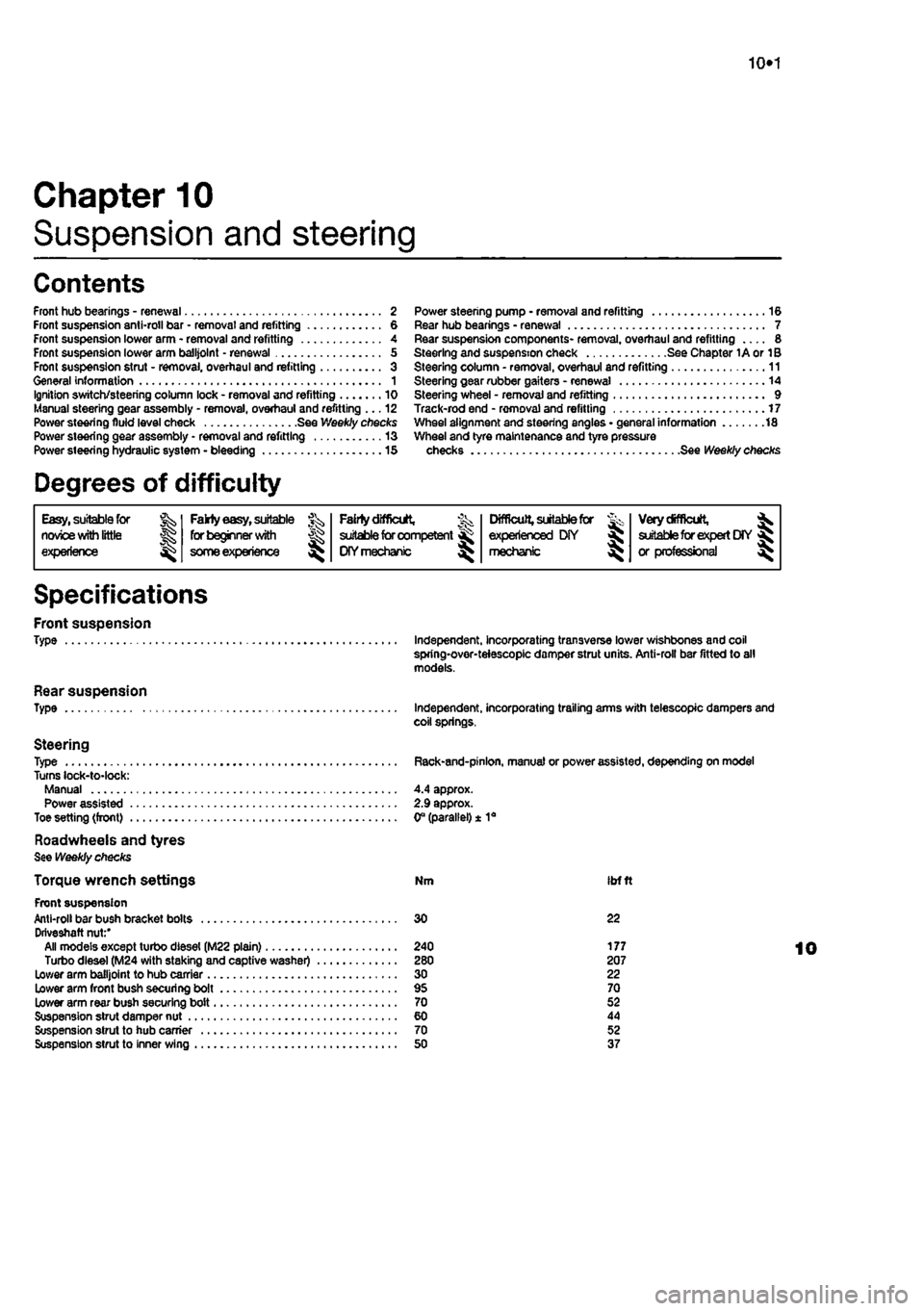
10*1
Chapter 10
Suspension and steering
Contents
Front hub bearings - renewal 2 Front suspension anti-roll bar • removal and refitting 6 Front suspension lower arm - removal and refitting 4 Front suspension lower arm balljolnt - renewal 5 From suspension strut - removal, overhaul and refitting 3 General information 1 Ignition switch/steering column lock - removal and refitting 10 Manual steering gear assembly - removal, overhaul and refitting ... 12 Power steering fluid level check See Weekly checks Power steering gear assembly - removal and refitting 13 Power steering hydraulic system - bleeding 15
Degrees of difficulty
Power steering pump • removal and refitting 16 Rear hub bearings - renewal 7 Rear suspension components- removal, overhaul and refitting 8 Steering and suspension check See Chapter 1A or 1B Steering column - removal, overhaul and refitting 11 Steering gear rubber gaiters - renewal 14 Steering wheel - removal and refitting 9 Track-rod end - removal and refitting 17 Wheel alignment and steering angles • general information 18 Wheel and tyre maintenance and tyre pressure checks See Weekly checks
Easy, suitable for nowoe with little
Jg experience ^
Fakty easy,
suitable for beginner
with
J£>
some experience
^
FaMy difficult,
% suitable for competent ^
DIY mechanic
^
Difficult,
suitable for & experienced DIY « mechsmc ^
Very difficult,
^ suitable for expert
DIY
fij or professional ^
Specifications
Front suspension Type
Rear suspension Type
Steering Type Turns lock-to-lock: Manual Power assisted Toe setting (front)
Roadwheeis and tyres See Weekly checks
Torque wrench settings Front suspension Anti-roll bar bush bracket bolts Driveshaft nut:' All models except turbo diesel (M22 plain) Turbo diesel (M24 with staking and captive washer) Lower arm balljoint to hub carrier Lower arm front bush securing bolt Lower arm rear bush securing bolt Suspension strut damper nut Suspension strut to hub carrier Suspension strut to inner wing
Independent, incorporating transverse lower wishbones and coil spring-over-teiescopic damper strut units. Anti-roll bar fitted to all models.
Independent, incorporating trailing arms with telescopic dampers and coil springs.
Rack-and-pinlon, manual or power assisted, depending on model
4.4 approx. 2.9 approx. 0° (parallel) ± 1a
Nm ibfft
30 22
240 177 280 207 30 22 95 70 70 52 60 44 70 52 50 37
Page 192 of 225
Suspension and steering 10*4
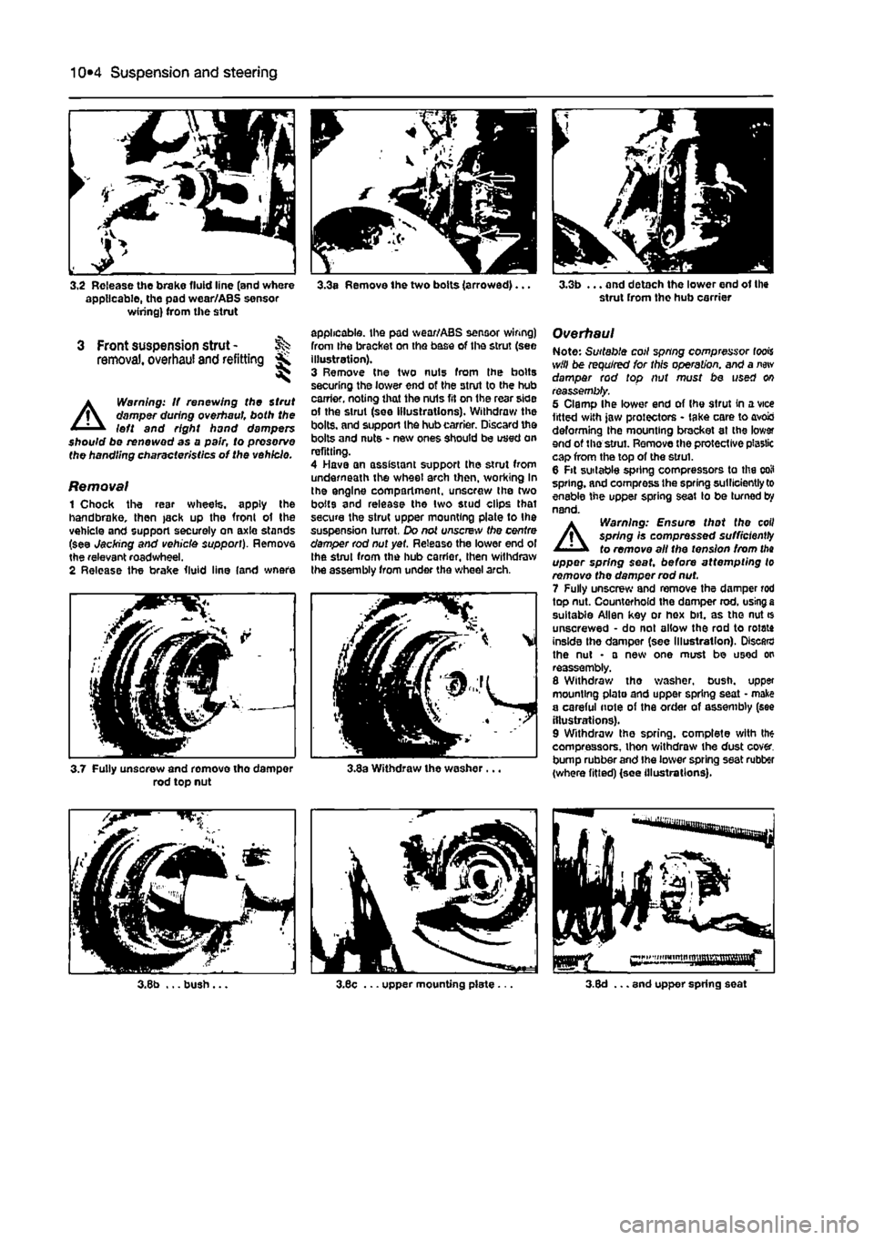
3.2 Release the brake fluid line (and where applicable, the pad wear/ABS sensor wiring) from the strut
3 Front suspension strut -removal, overhaul and refitting *
A
Warning: If renewing the Strut damper during overhaul both the left and right hand dampers should be renewed as a pair, to preserve the handling characteristics of the vehicle.
Removal 1 Chock the resr wheels, apply the handbrake, then jack up the fronl of the vehicle and support securely on axle stands (see Jacking and vehicle support). Remove the relevant roadwheel. 2 Release the brake fluid line (and wnere
3.3a Remove the two bolts (arrowed)...
applicable, the pad wear/ABS sensor wiring) from Ihe bracket on the base of the strut (see illustration). 3 Remove the two nuts from Ihe bolts securing the lower end of the strut to the hub carrier, noting that the nuls fit on the rear side of the strut (see illustrations). Withdraw the bolts, and support the hub carrier. Discard the bolts and nuts • new ones should be used on refitting. 4 Have an assistant support the strut from underneath the wheel arch then, working In the engine compartment, unscrew the two bolts and release the two stud clips that secure the strut upper mounting plate to the suspension turret. Do not unscrew the centre damper rod nut yet. Release the lower end ol the strut from the hub carrier, then withdraw the assembly from under the wheel arch.
3.7 Fully unsorew and remove tho damper rod top nut 3.3a Withdraw the washer.
3.3b ... and detach the lower end of the strut from the hub carrier
Overhaul Note: Suitable coil spring compressor fools will be required for this operation, and a
new
damper rod top nut must be used on reassembly. 5 Clamp Ihe lower end of Ihe strut in a vice fitted with jaw protectors - take care to avois deforming the mounting bracket at the lower end of the strut. Remove the protective plastic cap from the top of the strut. 6 Fit suitable spring compressors to the coil spring, and compress Ihe spring sutllciently to enable the upper spring seat to be turned by nand.
A
Warning: Ensure that the coil spring Is compressed sufficiently to remove all the tension from
tha
upper spring seat, before attempting to remove the damper rod nut. 7 Fully unscrew and remove the damper rod top nut. Countorhofd the domper rod. using
a
suitable Allen key or hex bit. as tho nut * unscrewed • do not allow the rod to rotate inside the damper (see Illustration). Discard the nut • a new one must be used on reassembly. 8 Withdraw tho washer, bush, upper mounting plate and upper spring seat • make a careful note of the order of assembly (see illustrations). 9 Withdraw the spring, complete with the compressors, thon v/ithdraw the dust cover, bump rubber and Ihe lower spring seat rubber (where fitted) (see illustrations).
Page 193 of 225
Suspension and steering 10*5
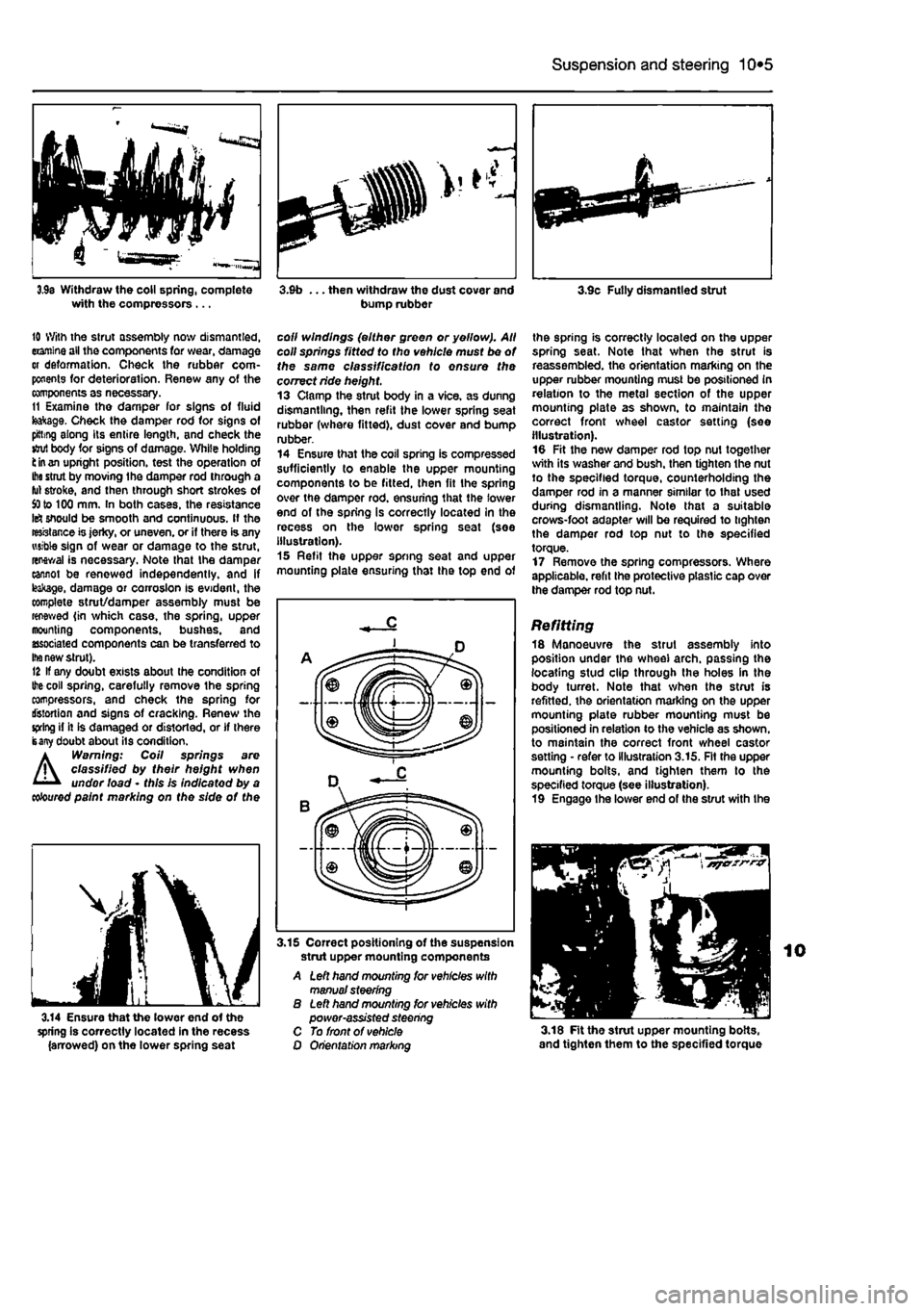
3,9s Withdraw the coll spring, complete with the compressors ... 3.9b ... then withdraw the dust cover and bump rubber 3.9c Fully dismantled strut
10 With the strut assembly now dismantled, examine all the components tor wear, damage or deformation. Check the rubber com-ponents for deterioration. Renew any of the components as necessary. 11 Examine tho damper for signs of fluid teakage. Check the damper rod for signs of pitting along its entire length, and check the stjul body for signs of damage. White holding fc
in an
upright position, test the operation of
Ihe
stmt by moving Ihe damper rod through a fut stroke, and then through short strokes of
SO
to 100 mm. In both cases, the resistance Id should be smooth and continuous. If the resistance is jerky, or uneven, or if there is any wsible sign of wear or damage to the strut, renewal is necessary. Note that the damper cannot be renewed independently, and if leakage, damage or corrosion Is evident, the complete strut/damper assembly must be renewed {in which case, the spring, upper mounting components, bushes, and associated components can be transferred to
Ihe
new strut). 12 If any doubt exists about the condition of
Ihe
coil spring, carefully remove the spring compressors, and check the spring for distortion and signs of cracking. Renew the spring if it is damaged or distorted, or if there isany doubt about its condition. a Warning: Coil springs are /j\ classified by their height when '
11
• undor load • this Is indicatod by a
coloured
paint marking on the side of the
coll windings (either green or yellow). All coll springs fitted to tho vehicle must be of the same classification to ensure the correct ride height. 13 Clamp the strut body in a vice, as dunng dismantling, then refit the lower spring seat rubber (where fitted), dust cover and bump rubber. 14 Ensure that the coil spring is compressed sufficiently to enable the upper mounting components to be fitted, then fit the spring over the damper rod. ensuring that the lower end of the spring is correctly located In the recess on the lower spring seat (soe illustration). 15 Refit the upper spring seat and upper mounting plate ensuring that the top end of
the spring is correctly located on the upper spring seat. Note that when the strut is reassembled, the orientation marking on the upper rubber mounting must be positioned in relation to the metal section of the upper mounting plate as shown, to maintain the correct front wheel castor setting (see illustration). 10 Fit the new damper rod top nut together with its washer and bush, then tighten the nut to the specified torque, counterholding the damper rod in a manner similar to that used during dismantling. Note that a suitable crows-foot adapter will be required to tighten the damper rod top nut to the specified torque. 17 Remove the spring compressors. Where applicable, refit the protective plastic cap over the damper rod top nut.
Refitting 18 Manoeuvre the strut assembly into position under the wheel arch, passing the locating stud clip through the holes in the body turret. Note that when the strut is refitted, the orientation marking on the upper mounting plate rubber mounting must be positioned in relation to the vehicle as shown, to maintain the correct front wheel castor setting • refer to illustration 3.15. Fit the upper mounting bolts, and tighten them to the specified torque (see illustration). 19 Engage Ihe lower end of the strut with the
3.14 Ensure that the lower end of the spring is correctly located in the recess (arrowed) on the lower spring seat
3.15 Correct positioning of the suspension strut upper mounting components A Left hand mounting for vehicles with manual steering B Left hand mounting tor vehicles with power-assisted steering C To front of vehicle O Orientation marking 3.18 Fit the strut upper mounting bolts, and tighten them to the specified torque
Page 206 of 225
Bodywork and fittings
11
*5
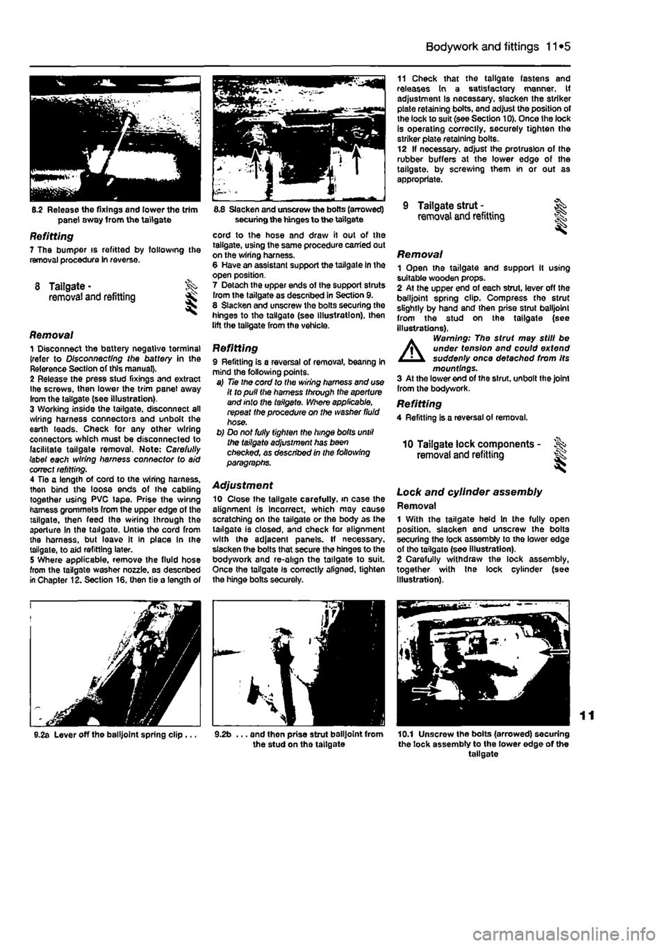
8.2 Release the fixings and lower the trim panel away from the tailgate
Refitting 7 The pumper is refitted by following the removal procedure In reverse.
8 Tailgate- ^ removal and refitting
Removal 1 Disconnect the battery negative tormina) {refer to D/sconnecf/ng the battery In the Reference Section of this manual}. 2 Release the press stud fixings and extract ihe screws, then lower the trim panel away from the tailgate (see illustration). 3 Working inside the tailgate, disconnect all wiring harness connectors and unbolt the earth leads. Check for any other wiring connectors which must be disconnected to facilitate tailgate removal. Note: Carefully label each wiring harness connector (o aid correct refitting. 4 Tie a length of cord to the wiring harness, then bind the loose ends of the cabling together using PVC tape. Prise the winng harness grommets from the upper edge of the tailgate, then feed the wiring through the aperture in the tailgate. Untie the cord from the harness, but leave it In place In the tailgate, to aid refitting later. 5 Where applicable, remove the fluid hose from the tailgate washer nozzle, as described in Chapter 12. Section 16. then tie a length of
8.2a Lever off the balljoint spring clip...
8.8 Slacken and unscrew the bolts (arrowed) securing the hinges to the tailgate
cord to the hose and draw it out of the tailgate, using the same procedure carried out on the wiring harness. 8 Have an assistant support the tailgate in the open position. 7 Detach the upper ends of the support stmts from the tailgate as described in Section 9. 8 Slacken and unscrew the bolts securing tho hinges to the tailgate (seo illustration), then lift the tailgate from the vehicle.
Refitting 9 Refitting is a reversal of removal, bearing in mind the following points. a) Tie the cord to the wiring harness and use It to pull the harness through the aperture and into the tailgate. Where applicable, repeat the procedure on the washer fluid hose. b) Do not fully tighten the hinge bolts until the tailgate adjustment has been checAed, as described in the following paragraphs.
Adjustment 10 Close the tailgate carefully, in case the alignment is Incorrect, which may cause scratching on the tailgate or the body as the tailgate is closed, and check for alignment with the adjacent panels. If necessary, slacken the bolts that secure the hinges to the bodywork and re-align the tailgate to suit. Once the tailgate is correctly aligned, tighten the hinge bolts securely.
9.2b ... and then prise strut balljoint from the stud on tho taitgate
11 Check that the tailgate fastens and releases In a satisfactory manner. If adjustment Is necessary, slacken the striker plate retaining bolts, and adjust the position of the lock to suit (see Section 10). Once the lock is operating correctly, securely tighten the striker plate retaining bolts. 12 If necessary, adjust the protrusion of the rubber buffers at the lower edge of the tailgate, by screwing them in or out as appropriate.
9 Tailgate strut - ^ removal and refitting
Removal 1 Open the tailgate and support it using suitable wooden props. 2 At the upper end of each strut, lever off the balljoint spring clip. Compress tho strut slightly by hand and then prise strut balljoint from the stud on the tailgate (see illustrations),
A
Warning: The strut may still be under tension and could extend suddenly once detached from Its mountings. 3 At the lower end of the strut, unbolt the joint Irom the bodywork. Refitting 4 Refitting is a reversal of removal.
10 Tailgate lock components -removal and refitting ^
Lock and cylinder assembly Removal 1 With the tailgate held In the fully open position, slacken and unscrew the bolts securing the lock assembly to tho lower edge of tho tailgate (soo illustration). 2 Carefully withdraw the lock assembly, together with tne lock cylinder (see Illustration).
10.1 Unscrew the bolts (arrowed) securing the lock assembly to the lower edge of the tailgate
Page 224 of 225
Body electrical systems 12*11
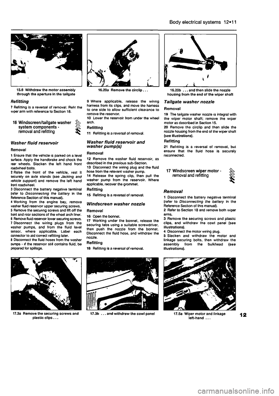
15.6 Withdraw the motor assembly through the aperture in the tailgate
Refitting 7 Refitting is a reversal of removal. Refit the wiper arm with reference to Section 16.
16 Windscreen/tailgate washer % system components • ^ removal and refitting ^
Washer fluid reservoir
Removal 1 Ensure that the vehicle is parked on a level surface. Apply the handbrake and chock the rear wheels. Slacken the left hand front roadwheel bolts. 2 Raise the front of the vehicle, rest it securely on axle stands (see Jacking and vehicle support) and remove the left hand front roadwheel. 3 Disconnect the battery negative terminal {refer to Disconnecting the battery In the Reference Section of this manual). 4 Working from the engine bay, remove washer fluid reservoir upper securing screws. 5 Remove the secunng screws and lift off the front and rear sections of the wheel arch liner. 6 Remove fluid reservoir lower securing screws. 7 Disconnect the sviring plugs from the washer pumps, and from the fluid level sensor, where applicable. Label each connector to aid correct refitting later. 8 Disconnect the fluid hoses from the washer tx/mps • if the reservoir still contains fluid, be prepared tor spillage.
16.20a Remove the circllp...
9 Where applicable, release the wiring harness from its clips, and move the harness to one side to allow sufficient clearance to remove the reservoir. 10 Lower the reservoir from under the wheel arch. Refitting 11 Refitting is a reversal of removal.
Washer fluid reservoir and washer pump(s)
Removal 12 Remove the washer fluid reservoir, as described in the previous sub-Section. 13 Disconnect the wiring plug and the fluid hose from the relevant washer pump. 14 Release the spring clip, then pull the washer pump from the reservoir. Where applicable, recover the grommet. Refitting 15 Refitting is a reversal of removal.
IV/nctecreen washer nozzle
Removal 16 Open the bonnet. 17 Working under the bonnet, release the securing tabs using a suitable screwdriver, then push the nozzle from the bonnet. Disconnect the fluid hose, and withdraw the nozzle. Refitting 18 Refitting is a reversal of removal.
housing from the end of the wiper shaft
Tailgate washer nozzle
Removal 19 The tailgate washer nozzle is integral with the wiper motor shaft; remove the wiper motor as described in Section 15. 20 Remove the circllp and then slide the nozzle housing from the end of the wiper shaft (see illustrations). Refitting 21 Refitting is a reversal of removal, but ensure that the fluid hose is securely reconnected.
17 Windscreen wiper motor -removal and refitting ^
Removal 1 Disconnect the battery negative terminal (refer to Disconnecting the battery In the Reference Section of this manual). 2 Refer to Section 18 and remove both wiper arms. 3 Remove the securing screws and plastic clips, and withdraw the cowl panel (see illustrations). 4 Disconnect the motor wiring plug. 5 Slacken and withdraw the motor and linkage securing bolts, then withdraw the assembly from the bulkhead (see illustrations).
17.3a Remove the securing screws and plasUc clips... 17.3b ... and withdraw the cowl panel 17.5a Wiper motor and linkage left-hand ...