key FIAT PUNTO 1998 176 / 1.G Owner's Manual
[x] Cancel search | Manufacturer: FIAT, Model Year: 1998, Model line: PUNTO, Model: FIAT PUNTO 1998 176 / 1.GPages: 225, PDF Size: 18.54 MB
Page 180 of 225
9*4 Braking system
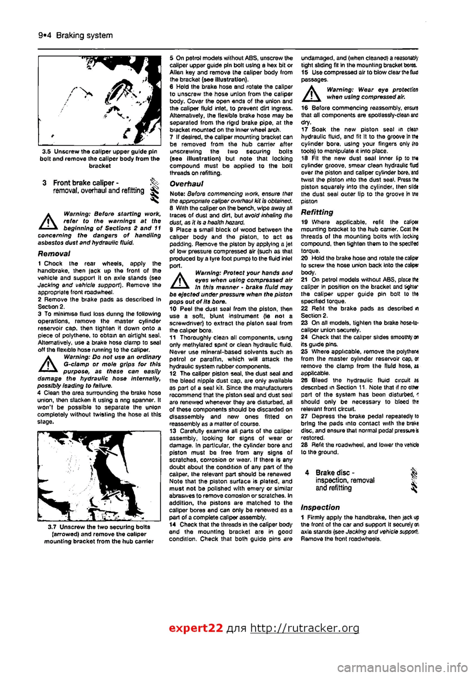
3.5 Unscrew the caliper upper guide pin bolt and remove tho caliper body (torn the bracket
3 Front brake caliper -removal, overhaul and refitting ^
A
Warning: Before starting work, refer to the warnings at the beginning of Sections 2 and 11 concerning the dangers of handling asbestos dust and hydraulic fluid.
Removal 1 Chock the rear wheels, apply the handbrake, then |ack up the front of the vehicle and support it on axle stands {see Jacking and vehicle support). Remove the appropriate front roadwheel. 2 Remove the brake pads as described In Section 2. 3 To minimise fluid loss dunng the following operations, remove the master cylinder reservoir cap. then
tig hi en
it down onto a piece of polythene, to obtain an airtight seat. Alternatively, use a brake hose clamp to seal off the flexible hose running to the caliper.
A
Warning: Do not use an ordinary G-clamp or mole grips for this purpose, as these can easily damage the hydraulic hose Internally, possibly leading to failure. 4 Clean the area surrounding the brake hose union, then slacken ft using a ring spanner. It won't be possible to separate the union completely without twisting the hose ai this slage.
3.7 Unscrew the two securing bolts (arrowed) and remove the caliper mounting bracket from the hub carrier
5 On petrol models without ABS, unscrew the caliper upper guide pin bolt using a hex bit or Allen key and remove the caliper body from the bracket (see illustration). 6 Hold the brake hose and rotate the caliper to unscrew the hose union from the caliper body. Cover the open ends of the union and the caliper fluid inlet, to prevent dirt Ingress. Alternatively, Ihe flexible brake hose may be separated from the rigid brake pipe, at the bracket mounted on the Inner wheel arch. 7 If desired, the caliper mounting bracket can be removed from the hub carrier after unscrewing ihe two securing bolts (see Illustration) but note that locking compound must be applied to the bolt threads on refitting.
Overhaul Note: Before commencing work, ensure that the appropriate caliper overhaul kit
Ss
obtained. 8 With the caliper on the bench, wipe away all (races of dust and dirt, but avoid inhaling the dust, as It
Is
a health hazard. 9 Place a small block of wood between the caliper body and tho piston, to act as padding. Remove the piston by applying a Jet of low pressure compressed air (such as that pioduced by a tyre foot pump) to the fluid inlel port.
A
Warning: Protect your hands and eyes when using compressed air In this manner • brake fluid moy be ejected under pressure when the pisfon pops out of Its bore. 10 Peel the dusi seal from the piston, then use a soft, blunt instrument (ie not a screwdriver) to extract the piston seal from the caliper bore. 11 Thoroughly clean all components, U9tng only methylated spint or clean hydraulic fluid, Never use mineral-based solvents such as petrol or paraffin, which will attack Ihe hydraulic system rubber components. 12 The caliper piston seal, the dust seal and the bleed nipple dust cap, a/e oniy available as part of a seat kit. Since the manufacturers recommend that the piston seal and dust seal are renewed whenever they are disturbed, all of these components should be discarded on disassembly and new ones fitted on reassembly as a matter of course. 13 Carefully examine all parts of the caliper assembly, looking for signs of wear or damage. In particular, the cylinder bore and piston must be free from any signs of scratches, corrosion or wear. If there is any doubt about ihe condition of any part of the caliper, the relevant port should be renewed Note that the piston surface is plated, and must not be polished with emery or similar abrasives to remove corrosion or scratches. In addition, the pistons are matched to the caliper bores and can only be renewed as a part of a complete caliper assembly. 14 Check that the threads in the caliper body and the mounting bracket are in good condition, Check that both guide pins are
undamaged, and (when cleaned) a reasons^' tight sliding fit In the mounting bracket bores. 15 UsecompressedairtOblow clear the IkuJ passages. Warning: Wear eye protection when using compressed
air.
16 Before commencing reassembly, en$vr« that all components are spotlessly-clean
and
dry. 17 Soak the new piston seal m clean hydraulic fluid, and fit it to the groove
In
tftt cylinder bore, using your fingers only (rift tools) to manipulate it into place. 18 Fit the new dust seal inner ftp to tne cylinder groove, smear clean hydraulic Hud over the piston and caliper cylinder
bore, and
twist ihe pfaton into the dust seal. Press tne piston squarely Into the cylinder, then sildt the dust seal outer lip to tho groove in we piston
Refitting 19 Where applicable, refit the caliper mounting bracket to thB hub earner. Ccaitto threads ol the mounting bolts with locking compound, then tighten them to the speclfed torque. 20 Hold the brake hose and rotate Ihe calip* to screw the hose union back Into the caliper body. 21 On petrol models without ABS, place the caliper In position on the bracket and tighter the caliper upper guide pin bolt to the specified torque. 22 Relit ihe brake pads as described m Section 2. 23 On all models, tighten the brake hose-to-callper union securely. 24 Check that the caliper slides smoothly
on
its guide pins. 25 Where applicable, remove the polytbste from the master oyhnder rasarvoir cap, or remove tho clomp from the fluid hose, ai applicable. 26 Bleed tho hydraulic fluid circuit as desenbed m Section 11. Note that if rootMf part of the system has been disturbed, < should only be necessary to bleed tha relevant front circuit, 27 Depress the brake pedal repeatedly to bring ihe pads into contact with ihe brake disc, and ensure that normal pedal
pressure is
restored. 28 Refit the roadwheel, and lower tha veti'cfc lo ihe ground.
4 Brake disc -
inspection,
removal
and
refitting
Inspection 1 Firmly apply the handbrake, then jaefcup the front of the car and support It securely
oft
axle stands (see Jacking and vehicle
support1,.
Remove the front roadwhesls.
expert22 f
a http://rutracker.org
Page 192 of 225
Suspension and steering 10*4
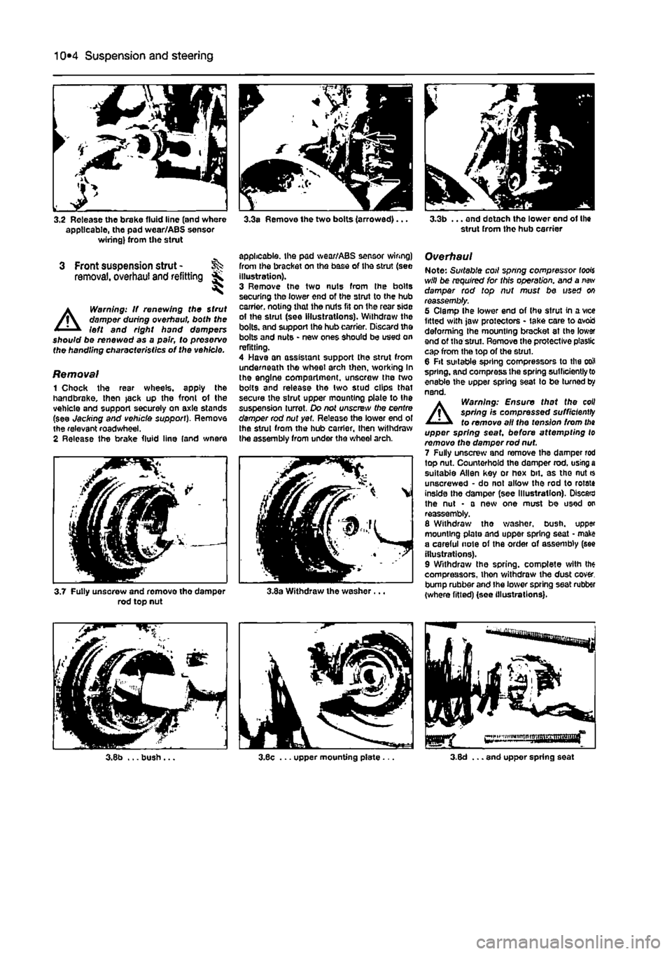
3.2 Release the brake fluid line (and where applicable, the pad wear/ABS sensor wiring) from the strut
3 Front suspension strut -removal, overhaul and refitting *
A
Warning: If renewing the Strut damper during overhaul both the left and right hand dampers should be renewed as a pair, to preserve the handling characteristics of the vehicle.
Removal 1 Chock the resr wheels, apply the handbrake, then jack up the fronl of the vehicle and support securely on axle stands (see Jacking and vehicle support). Remove the relevant roadwheel. 2 Release the brake fluid line (and wnere
3.3a Remove the two bolts (arrowed)...
applicable, the pad wear/ABS sensor wiring) from Ihe bracket on the base of the strut (see illustration). 3 Remove the two nuts from Ihe bolts securing the lower end of the strut to the hub carrier, noting that the nuls fit on the rear side of the strut (see illustrations). Withdraw the bolts, and support the hub carrier. Discard the bolts and nuts • new ones should be used on refitting. 4 Have an assistant support the strut from underneath the wheel arch then, working In the engine compartment, unscrew the two bolts and release the two stud clips that secure the strut upper mounting plate to the suspension turret. Do not unscrew the centre damper rod nut yet. Release the lower end ol the strut from the hub carrier, then withdraw the assembly from under the wheel arch.
3.7 Fully unsorew and remove tho damper rod top nut 3.3a Withdraw the washer.
3.3b ... and detach the lower end of the strut from the hub carrier
Overhaul Note: Suitable coil spring compressor fools will be required for this operation, and a
new
damper rod top nut must be used on reassembly. 5 Clamp Ihe lower end of Ihe strut in a vice fitted with jaw protectors - take care to avois deforming the mounting bracket at the lower end of the strut. Remove the protective plastic cap from the top of the strut. 6 Fit suitable spring compressors to the coil spring, and compress Ihe spring sutllciently to enable the upper spring seat to be turned by nand.
A
Warning: Ensure that the coil spring Is compressed sufficiently to remove all the tension from
tha
upper spring seat, before attempting to remove the damper rod nut. 7 Fully unscrew and remove the damper rod top nut. Countorhofd the domper rod. using
a
suitable Allen key or hex bit. as tho nut * unscrewed • do not allow the rod to rotate inside the damper (see Illustration). Discard the nut • a new one must be used on reassembly. 8 Withdraw tho washer, bush, upper mounting plate and upper spring seat • make a careful note of the order of assembly (see illustrations). 9 Withdraw the spring, complete with the compressors, thon v/ithdraw the dust cover, bump rubber and Ihe lower spring seat rubber (where fitted) (see illustrations).
Page 197 of 225
Suspension and steering 10*9
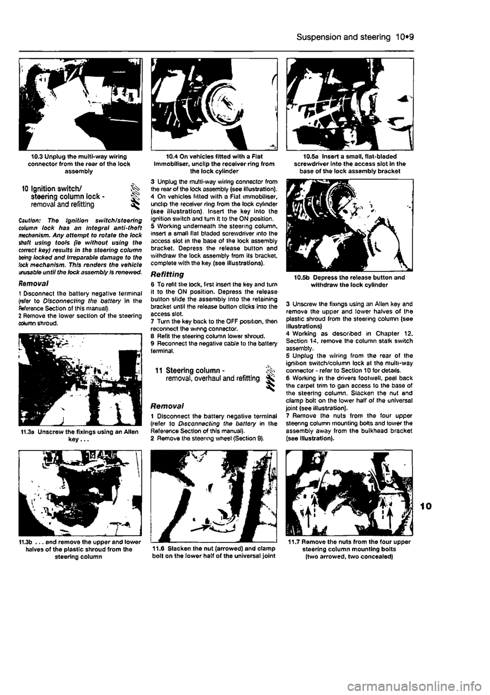
10.3 Unplug the multi-way wiring connector from the rear of tho lock assembly
10 Ignition switch/ steering column lock • ^ removal and refitting ^
Caul/on: The Ignition switch/steering column lock has on integral and-tho ft mechanism. Any attempt to rofafe tho lock shaft using tools (lo without using the correct key) results in the steering column tebg locked and Irreparable damage to the lock mechanism. This renders the vehicle
unusable
until tho lock assembly Is renewed.
Removal 1 Disconnect the battery negative terminal (refer to Disconnecting the battery In the Reference Section of this manual}. 2 Remove the lower section of the steering column shroud.
11.3a Unscrew the fixings using an Allen key...
f
10.4 On vehicles fitted with a Flat Immobiliser, uncllp the receiver ring from the lock cylinder 3 Unplug the multi-way wiring connector from the rear of the lock assembly (see illustration). 4 On vehicles fitted with a Fiat immobiliser. uncltp the receiver ring from the lock cylinder (see illustration). Insert the key Into the ignition switch and turn it to the ON position. 5 Working underneath the steering column, insert a small fiat bladed screwdriver into the access slot in the base of the lock assembly bracket. Depress Ihe release button and withdraw the lock assembly from Its bracket, complete with the key (see illustrations).
Refitting 6 To refit the lock, first inserl the hey and turn it to the ON position. Depress the release button slide the assembly into the retaining bracket until the release button clicks Into the access slot. 7 Turn the key back to the OFF position, then reconnect the wmng connector. 8 Relit the steering column lower shroud. 9 Reconnect the negative cable to the battery terminal.
11 Steering column - ^ removal, overhaul and refitting jK
Removal 1 Disconnect the battery negative terminal (refer to Disconnecting the battery in the Reference Section of this manual). 2 Remove the steenng wheel (Section 9).
10.5a Insert a small, flat-bladed screwdriver into the access slot in the base of the lock assembly bracket
10.5b Depress tho release button and withdraw the lock cylinder
3 Unscrew the fixings using an Allen key and remove the upper and lower halves of the plastic shroud from the steering column (see illustrations) 4 Working as described in Chapter 12. Section 14. remove the column stalk switch assembly, 5 Unplug the wiring from the rear of the ignition switch/column lock at the multi-way connector • refer to Section 10 for details. 6 Working in the drivers footweli. peel back the carpet trim to gam access to the base of the steering column. Slacken the nut and clamp bolt on the lower half of the universal joint (see illustration). 7 Remove Ihe nuts from the four upper steenng column mounting bolts and lower the assembly away from the bulkhead bracket (see illustration).
11.7 Remove the nuts from the four upper steering column mounting bolts (two arrowed, two concealed)
11.3b ... end remove the upper and lower halves of the plastic shroud from the 11-6 Slacken the nut (arrowed) and clamp steering column bolt on the lower half of the universal joint
Page 203 of 225
11 *2 Bodywork and fittings
on vehicles with wax-based underbody protective coating, or the coating will be removed. Such vehicles should be inspected annually, preferably just prior lo Winter, when the underbody should be washed down, and any damage to the wax coating repaired. Ideally, a completely fresh coat should be applied. It would also be worth considering the use of such wax-based protection for injection into door panels, sills, box sections, etc, as an additional safeguard against rust damage, where such protection Is not provided by the vehicle manufacturer. After washing paintwork, wipe off with a chamois feather to give an unspotted clear finish. A coat of clear protective wax polish wilt give added protection against chemical pollutants in the air. If the paintwork sheen has duiled or oxidised, use a cleaner/polisher combination to restore the brilliance of the shine. This requires a little effort, but such dulling Is usually caused because regular washing has been neglected. Care needs to be taken with metallic paintwork, as special non-abrasive cleaner/polisher is required to avoid damage to the finish, Always check that the door and ventilator opening drain holes and pipes are completely clear, so that water can be drained out. Brightwork should be treated In the same way as paintwork. Windscreens and windows can be kept clear of the smeary film which often appears, by the use of proprietary glass cleaner. Nover use any form of wax or other body or chromium polish on glass.
Maintenance -upholstery and carpets
Mats and carpets should be brushed or vacuum-cleaned regularly, to keep them free of grit. If they are badly stained, remove them from the vehicle for scrubbing or sponging, and make quite sure they are dry before refitting. Seats and interior trim panels can be kept clean by wiping with a damp cloth. If they do become stained (which can be more apparent on light-coloured upholstery), use a little liquid detergent and a soft nail brush lo scour the grime out of the grain of the material. Do not forget to keep the headlining clean in the same way as the upholstery. When using liquid cleaners inside the vehicle, do not over-wet the surfaces being cleaned. Excessive damp could get Into the seams and padded interior, causing stains, offensive odours or even rot.
If the Inside of the vehicle gets wet accidentally, tt Is worthwhile taking some trouble to dry ft out property, particularly where carpets an involved. Do not leave oil or electric heaters inside the vehicle for this purpose.
4 Minor body damage -repair
Repairs of minor scratches In bodywork If the scratch Is very superficial, and does not penetrate to the metal of the bodywork, repair is very simple. Lightly rub the area of the scratch with a paintwork renovator, or a very fine cutting paste, to remove loose paint from the scratch, and to clear the surrounding bodywork of wax polish, Rinse the area with clean water. Apply touch-up paint to ihe scratch using a fine paint brush; continue to apply fine layers of paint until the surface of the paint In the scratch Is level with the surrounding paintwork. Allow Ihe new paint at least two weeks to harden, then blend it Into the surrounding paintwork by rubbing the scratch area with a paintwork renovator or a very fine cutting paste. Finally, apply wax polish. Where the scratch has penetrated right through to the metal of the bodywork, causing the metal to rust, a different repair technique Is required. Remove any loose rust from the bottom of the scratch with a penknife, then apply rust-inhibiting paint to prevent the formation of rust in the future. Using a rubber or nylon applicator, fill the scratch with bodystopper paste. If required, this paste can be mixed with cellulose thinners to provide a very thin paste which is ideal for filling narrow scratches. Before the stopper-paste in Ihe scratch hardens, wrap a piece of smooth cotton rag around the top of a finger. Dip the finger in cellulose thinners, and quickly sweep it across the surface of the stopper-paste in the scratch: this will ensure that the surface of the stopper-paste is slightly hollowed. The scratch can now be painted over as described earlier In this Section.
Repairs of dents in bodywork When deop denting of the vehicle's bodywork has taken place, the first task is to put) the dent out. until the affected bodywork almost attains rts onginal shape. There is little polnl in trying to restore Ihe original shape completely, as the metal in the damaged area will have stretched on impact, and cannot be reshaped fully to its original contour. It Is better to bring the level of the dent up to a point which is about 3 mm below the level of the surrounding bodywork. In cases where Ihe dent is very shallow anyway, It is not worth trying to pull it out at all. If the underside of the dent is accessible, it can be hammered out gently from behind, using a mallet with a wooden or plastic head, Whilst doing this, hold a suitable block of wood firmly against (he outside of Ihe panel, to absorb the impact from the hammer blows and thus prevent a large area of the bodywork from being 'belled-out".
Should the dent be In a section of (I* bodywork which has a double skin, or seme other factor making It Inaccessible from behind, a different technique is called for. Dull several small holes through the metal inside Ihe area - particularly in the deeper section. Then screw long self-tapping screws Into the holes, just sufficiently for them to gain a good purchase in the metal. Now the dent can be pulled out by pulling on the protruding heads of the screws with a pair of pliers. The next stage of the repair Is the removal of the paint from the damaged area, and from an inch or so of the surrounding 'sound' bodywork. This is accomplished most easily by using a wire brush or abrasive pad on a posver drill, although it can be done just as effectively by hand, using sheets of abrasive paper. To complete the preparation for filling, score the surface of the bare metal wflhi screwdriver or the tang of 8 file, or alternatively, drill small holes In the affected area. This will provide a really good 'key' for the filler paste. To complete the repair, see the Section on filling and respraying.
Repairs of rust holes or gashes in bodywork Remove all paint from the affected area, and from an inch or so of the surrounding 'sound' bodywork, using an abrasive pad
or a
wire brush on a power drill. If these are not available, a few sheets of abrasive paper wil do the job most effectively. With the paint removed, you will be able to judge the severity of the corrosion, and therefore decide whether to renew the whole panel (if this is possible) or to repair the affected area. New body panels are not as expansive as most people think, and it is often quicker and more satisfactory to fit a new panel than to attempt to repair large areas of corrosion. Remove all fittings from Ihe affected area, except those which will act as a guide to ttie original shape of the damaged bodywork (eg headlight shells etc). Then, using tin snips
or a
hacksaw blade, remove all loose metal snd any other metal badly affected by corrosion. Hammer the edges of the hole inwards, in order to create a slight depression for the filer paste. Wire-brush the affected area to remove tha powdery rust from the surface of the remaining metal. Paint Ihe affected area with rust-inhibiting paint, if the beck of the rusted area is accessible, treat this also. Before filling can take place, ft will be necessary to block the hole in some
way.
TNs can be achieved by the use of aluminium cr plastic mesh, or aluminium tape. Aluminium or plastic mesh, or glass-fibre matting, is probably the best material to use for a large hole. Cut a piece to tha approximate size and shape of tho hole to b« filled, then position it In the hole so that its edges are below the level of the surrounding bodywork. It can be retained in position by
Page 222 of 225
Body electrical systems 12*9
3 Undo the mounting screws and lift out the speaker (see Illustration). Unplug the wiring at the connector. 4 Refitting is a reversal of removal,
Rear parcel shelf speakers 5 Working underneath the relevant parcel shetf support bracket, remove the securing screws and lower the loudspeaker from the support bracket. Unplug the wiring at the connector (see illustration). 6 Refitting is a reversal of removal.
11 Radio aerial - J^s removal and refitting ^
Removal 1 Carefully prise off the plastic cap. then remove the securing screws and withdraw the aerial from the roof. 2 Oraw the aerial co-axial cable through the roof aperture and disconnect it. If there is insufficient slack In the aerial cable, remove the courtesy light unit/overhead panel from the inside of the vehicle (as described earlier in this Chapter) to gain access to the cable connector,
Refitting 3 Refitting Is a reversal of removal, but ensure that seal between the aerial housing and the roof panel is in good condition.
12.2 Removing the radio/cassette unit using the special extraction tools
12.3 Disoonnect the wiring plugs from the rear of the unit. Note the bayonet fuse (arrowed) which is a push fit In the rear of the unit
10.3 Lift out the speaker and unplug the wiring at the connector
12 Radio/cassette player -removal and refitting ^
Removal Note: Once the battery has been disconnected, the radio/cassette unit cannot be re-activated until the appropriate security code has been entered. Do not remove the unit unless the appropriate code Is known. 1 Disconnect the battery negative terminal (refer to Disconnecting the battery in the Reference Section of this manual). 2 Insert the special extraction tools supplied with the vehicle into the holes on either side of the radio/cassette unit. Press them home until the Internal clips can be felt to release (see illustration). 3 Pull the unit forwards from the facia, then disconnect the wiring plugs and the aerial lead from the rear of the unit. Note the bayonet fuse, which is a push fit in the rear of the unit, (see illustration).
Refitting A Refitting is a reversal of removal, ensuring that the wiring Is routed freely behind the unit.
13 Speedometer drive cable - % removal and refitting Ss ^
Note: Later vehicles are fitted with an electronic transducer in place of the mechanical speedometer drive. This is mounted on the fransm/ss/on casing; refer to Chapter 7A, Section 3, for details.
Removal 1 Remove the instrument panel as described in Section 7. 2 Working in the engine compartment, unscrew the sleeve securing the cable end to gearbox, then pull the cable from gearbox. 3 Where applicable, release the cable from the brackets in the engine compartment bulkhead, then pull the cable through into the engine compartment. If necessary, pull the cable grommet from the bulkhead.
10.S Lower the loudspeaker from the support brackot and unplug tho wiring at the connector
Refitting 4 Refitting is a reversal of removal, bearing in mind the following points: a} Ensure that the bulkhead grommet is securely seated. b) Refit the instrument panel with reference to Section 7. c) Note that certain models have alignment marks on the cable outer for use when refitting. The marks should be aligned with the bulkhead bracket when the cable is correctly refitted and routed.
14 Switches -removal and refitting ^
Steering column stalk switches Note: On vehicles equipped with sfeezing wheel-mounted radio controls, the column stalk switch unit also incorporates the rotary contacts for the steering wheel switches. Removal 1 Disconnect the battery negative cable and position it away from the terminal. Turn the steering wheel so that the roadwheeis are pointing in the straight-ahead position. 2 Refer to Chapter 10 and remove the steering wheel from the column. 3 Remove the screws and lift off the upper and lower steering column shrouds. 4 Using an Allen key. slacken Ihe clamp ring at the rear of the switch unit (see illustration),
14.4 Using an Allen key, slacken the clamp ring at the rear of the switch unit