key FIAT PUNTO 1998 176 / 1.G User Guide
[x] Cancel search | Manufacturer: FIAT, Model Year: 1998, Model line: PUNTO, Model: FIAT PUNTO 1998 176 / 1.GPages: 225, PDF Size: 18.54 MB
Page 71 of 225
DOHC (16-valve) petrol engine in-car repair procedures 2B*11
camshaft cover plate... 25 Locate the cam follower retaining tools in position and refit the cylinder head extension
as
described In Section 8.
10
Cylinder head - &
removal and
refitting S
Removal Note; The cylinder head bolts are of special
sekned
design and a Fiat tool should be
obtained
to unscrew them. A Ton key will not
JSt however
in practise It was found that a dose-httlng Alien key could be used as an itemative. 1 Drain the cooling system as described in Chapter 1A. 2 Remove the cylinder head extension as oescAbed
m
Section 8. 3 Disconnect the radiator hose from the thermostat housing on the left-hand end of
Ihe
cylinder head. 4 Disconnect the heater hose from the outlet
at the
rear of the cylinder head. 5 Disconnect the coolant temperature sensor md temperature gauge sensor wiring plugs
torn
the left-hand end of the cylinder head. 9 Undo the engine oil dipstick tube bracket retaining bolt and the two bolts securing the wing harness support clips to the inlet marriold lower section. 7 Undo Ihe retaining nuts and separate the ixhaust system front pipe from the exhaust manifold flange.
8
Check that nothing remains attached to the cinder head likely to impede removal. It Is assumed that the head will be removed complete with exhaust manifold and inlet manifold lower section. 9 Unscrew the cylinder head bolts half a turn K
e
time in the reverse order to that shown in (lustration 10.20a. When the bolts are free. «mwe them from their locations.. Id Lift the cylinder head from the block. If it is stuck tight rock the head to break the joint by mans of the manifolds. On no account drive
levers
into the gasket Joint, nor attempt to tap tf« head sideways, as it is located on positioning dowels. 11 Remove and discard the cylinder head gasket.
JK'
l^. 9.22b ... then apply RTV gasket sealant to the cover plate contact face 12 Refer to Chapter 20 for cylinder head dismantling and inspection procedures. Preparation for refitting 13 The mating faces of the cylinder head and cylinder block must be perfectly dean before refitting the head. Use a hard plastic or wooden scraper to remove all traces of gasket and carbon; also clean the piston crowns, Take particular care when cleaning the piston crowns as the soft aluminium alloy is easily damaged. Make sure that the carbon is not allowed to enter the oil and water passages -this Is particularly important for the lubncahon system, as carbon could block the oil supply to the engine's components. Using adhesive tape and paper, seal the water, oil and bolt holes in the cylinder block. To prevent carbon entering the gap between the pistons and bores, smear a little grease In the gap. After cleaning each piston, use a small brush to remove all traces of grease and carbon from the gap. then wipe away the remainder with a clean rag. Clean all the pistons in the same way. 14 Check the mating surfaces of the cylinder block and the cylinder head for nicks, deep scratches and other damage. If slight, they may be removed carefully with a file, but If excessive, machining may be the only alternative to renewal. If warpage of the cylinder head gasket surface Is suspected, use a straight-edge to check it for distortion. Refer to Part 0 of this Chapter if necessary. 15 Check the condition of the cylinder head bolts, and particularly their threads, whenever they are removed. Wash the bolts In a suitable
sequence
9.24 Lubricate the cam followers and place them in position in their respective bores solvent, and wipe them dry. Check each bolt for any sign of visible wear or damage, renewing them if necessary.
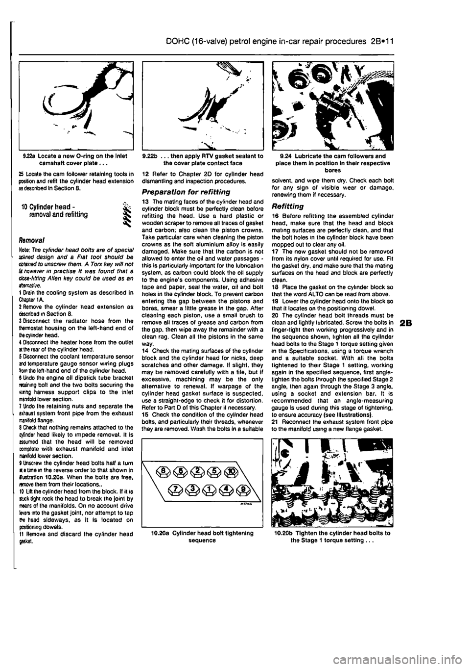
Refitting 18 Before refitting the assembled cylinder head, make sure that the head and block mating surfaces are perfectly clean, and that the bolt holes in the cylinder block have been mopped out to clear any oil, 17 The now gasket should not be removed from its nylon cover until required for use. Fit Ihe gasket dry, and make sure that the mating surfaces on the head and block are perfectly clean. 18 Place the gasket on the cylinder block so that the word ALTO can be read from above. 19 Lower the cylinder head onto the block so that it locates on the positioning dowel. 20 The cylinder head bolt threads must be clean and lightly lubricated. Screw the bolts in finger-tight then working progressively and in the sequence shown, lighten all the cylinder head bolts to the Stage 1 torquo setting given In the Specifications, using a torque wrench and a suitable socket. With all the bolts tightened to their Stage 1 setting, working again in the specified sequence, first angle-tighten the bolts through the specified Stage 2 angle, then again through the Stage 3 angle, using a socket and extension bar. It Is recommended that an angle-measuring gauge Is used during this stage ot tightening, to ensure accuracy (see Illustrations). 21 Reconnect the exhaust system front pipe to the manifold using a new flange gasket.
10.20b Tighten the cylinder head bolts to the Stago 1 torque setting ...
Page 79 of 225
Diesel engine in-car repair procedures
2C*11
5.31c ... followed by the Woodruff key
rocking motion to remove It, Note that the sprocket Is located by an integral key. Inspection 23 With the sprocket removed, examine the crankshaft oil seal for signs of leaking. If necessary, refer to Section 8 and renew it. 24 Check the sprocket teeth for damage. Also check the key and if necessary renew it. 25 Wipe clean the sprocket and crankshaft mating surfaces. Refitting 26 Slide the sprocket onto the crankshaft and engage the key with the slot In the crankshaft. 27 Refit the bolt, washer and spacer and tighten the bolt to the specified torque white holding the crankshaft stationary using the method described in paragraph 21. 28 Refit the timing belt as described in Sectton 4.
6.3a Support bracket positions on the camshaft cover
5.31a Use a puller to release the sprocket from the injection pump shaft
5.35 Tightening the injection pump sprocket bolt
Injection pump sprocket
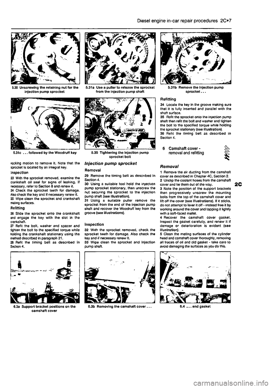
Removal 29 Remove the timing belt as described In Section 4. 30 Using a suitable tool hold Ihe injection pump sprocket stationary, then unscrew the nut securing the sprocket to the injection pump shaft (see illustration). 31 Using a suitable puller remove the sprocket from the end of the injection pump shaft and recover the Woodruff key from the groove (see illustrations),
Inspection 32 With the sprocket removed, check the sprocket teeth for damage. Also check the key and if necessary renew It. 33 Wipe clean the sprocket and injection pump shaft,
5.31b Removo tho injection pump sprocket...
Refitting 34 Locate the key in the groove making sure that it is fully Inserted and parallel with the shaft surface. 35 Refit the sprocket onto the Injection pump shaft then refit the bolt and washer and tighten the bolt to the specified torque while holding the sprocket stationary (soe illustration). 36 Refit the timing belt as described In Section 4,
6 Camshaft cover -removal and refitting ^
Removal 1 Remove the air ducting from the camshaft cover as described in Chapter 40, Section 2. 2 Unclip the coolant hoses from the camshaft cover and tie them out of tho way. 3 Note the position of the support brackets then progressively unscrew the mounting bolts from the top of the camshaft cover and lilt off the cover (see illustrations). If it sticks, do not attempt to lever it off • instead free it by working around the cover and tapping it lightly with a soft-faced mallet. 4 Recover the camshaft cover gasket. Inspect the gasket carefully, and renew It if damage or deterioration is evident (see illustration). 5 Clean the mating surfaces of the cylinder head and camshaft cover thoroughly, removing all traces of oil and old gasket • take oaro to avoid damaging the surfaces as you do this.
6.4 ... and gasket
Page 80 of 225
2C*2 Diesel engine in-car repair procedures
Refitting 6 Locate a new gasket on the cylinder head and make sure tt Is correctly seated. 7 Lower the cover onto the gasket making sure the gasket Is not displaced, 8 Insert the mounting bolts and tighten them securely In a progressive sequence. Position Ihe support brackets as noted during removal. 9 Clip ihe coolant hoses in position then refil the air ducting.
7 Camshaft oil seal -renewal
8 Crankshaft oil seals -renswal I
9 Cylinder head -
removal
and refitting
1 Remove the timing belt and camshaft sprocket as descnbed in Sections 4 and 5. 2 Using a suitable hooked instrument, remove tho oil seal from the cylinder head taking care nol to damage the surface of the camshafl. Alternatively drill a small hole In tho oil seal and Insert a self-topping screw - the seal can then be removed by pulling on the screw with a pair of pliers. 3 Clean the seating In the cylinder head and tho end of the camshaft To prevent damage to the new oil seal as It is being fitted, wrap some adhesive tape around the end ol the camshaft and lightJy oil it. 4 Dip tho new ail s«al In oil then locate it over Ihe camshaft making sure that the sealing lips are facing inwards. 5 Using a suitable tubular drift, drive the oil seal squarely into the cylinder h*ad. Remove the adhesive tap© 6 Refit the camshaft sprocket and timing belt with reference to Sections 6 and 4.
Front (right-hand side) oil seal t The front oil seal is located in the oil pump casing on the front of the crankshaft. Remove the timing belt as described in Section 4 and the crankshaft sprocket as described in Section 5, 2 Using a suitable hooked instrument, remove the oil seal from the oil pump casing taking care not to damage the surface of the crankshaft. Alternatively drill a small hole In the oil soal and insert a self-tapping screw - the seal can then be removed by pulling on the screw with a pair of pliers. 3 Clean the seating in the oH pump and the surface of the crankshaft. To prevent damage to the new off seal as It Is being fitted, wrap some adhesive tape around the end of tha crankshaft and lightly oil it. 4 Oip the new oii seal In oil then otter it up to the oil pump casing making sure that the sealing Hps are facing inwards,
8.Ba Rear oil soal and housing
5 Using a suitable tubular drift, driva the oil sea! squarely into the casing. Remove the adhesive tape. 6 Refit the crankshaft sprocket and timing belt with reference to Sections 5 and 4.
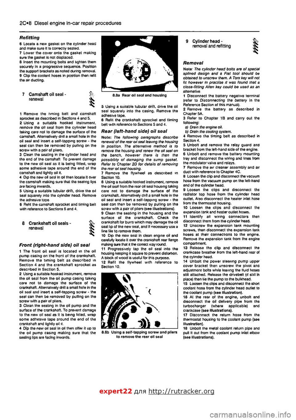
Rear (left-hand side) oil seal Note: The following paragraphs describe renewal of the rear oil seal leaving the housing In position. The alternative mathod is to remove the housing and renew the oil seel on the bench, however there is then the possibility of damaging the sump gasket. Refer to Chapter 2D for details of removing the mar oil sea! housing. 7 Ramove the flywheel as described in Section 10. 8 Using a suitable hooked Instrument. remove 1he oil seat from the roar oil seal housing taking care not to damage Ihe surface of Ihe crankshaft. Alternatively dnll a small hole In the o» seal and insert a self-tapping screw - the seal can ihan be removed by pulling on the screw with a pair of pliers (see Illustrations), 9 Clean the seating in the housing and the surface of the crankshaft. Check the crankshaft for burrs which may damage the oil seal tip of tno new saal, and It necessary use a Una file to removothem. 10 Dip the new soal in clean engine oil and carefully tocato it over tho crankshafl rear Range making sure that
H
the correct way round. 11 Progressively tap the oH seal into the housing keepfng it square to prevent distortion. A block of wood is useful for this purpose. 12 Refit the flywheel with reference to Section 10.
I
5.8b Using a self-tapping screw and pliers to remove the rear oil seal
Removal Note: The cylinder head bolts are of special splined design and a Fiat tool should be obtained to unscrew them. A Torn key will
not
fit however In practise It was found that a close-fitting Allen key could bo used as an alternative. 1 Disconnect the battery negative terminal (refer to Disconnecting the battery in the Reference Section of this manual), 2 Remove tha battery as described In Chapter 5A. 3 Refer to Chapter IB and carry out the following: o) Drain the engine oil, b) Drain the cooling system. 4 Remove the timing belt as described in Section 4. 5 Unbolt and remova the relay guard and bracket from the left-hand side of the engine. 6 Unbolt and remove the battery mounting tray and disconnect the wiring and lines from the modulator valva and relays. 7 Remove the air eleanar assembly and air duct with reference lo Chapter 4C. 8 Loosen the clip and disconnect the vacuum hosa from the vacuum pump on the left-hand end of the cylinder head. 9 Loosen Ihe clips and disconnect the radiator top hose from the cylinder head outlet. Also disconnect the heater inlet hose from the thermostat housing, 10 Loosen the clips and disconnect the expansion tank and heater outlet hoses. 11 Identify all wiring connectors then disconnect them from the cylinder head, 12 Unscrew the expansion tank mounting screws, then disconnect tha expansion tank hoses at their connections to the engine. Remove the expansion tank from tha engine compartment. 13 Release tha clip and disconnect ihe crankcase breather from the left-hand rear of the cylinder head. 14 Unbolt the power steering pump uppar cover bracket then unscrew the pivot ana adjustment bolts while leaving ihe tMd lioses still attached. Release the drivebelt (if still In place) then tie the pump to the bulkhead. 15 Loosen tha clips and disconnect Ihe short coolant hose from the cylinder head outlet to the coolant pump (soe illustration). 18 At the rear of the engine, unbolt and disconnect the oil delivery pipe from the turbocharger (where applicable) and crankcase (see Illustrations). 17 Disconnect the return hose from tha thermostat housing to the coolant pump (see Illustration), 18 Unbolt the metal coolant return pipe and pull it out from the coolant pump inlet elbow (see Illustrations).
expert22 flna http://rutracker.org
Page 96 of 225
2D*10 Engine removal and overhaul procedures
60 At the otl filter, unscrew the union nuts and disconnect the oil cooler lines/hoses then remove the oil cooler from the vehicle (see Illustration). Be prepared for some oil leakage. Note the fitted position of the hoses before disconnecting them so that they can be refitted correctly. 61 Disconnect the reversing light wiring from Ihe switch on the front of the transmission (see illustration) 82 Using an Allen key, unscrew the bolts securing the inner ends of the driveshafts to the flanges on the transmission. The right-hand driveshaft is disconnected from the Intermediate shaft flange on the rear of the engine. Recover the plates beneath the heads ol the driveshaft bolls (see illustrations). 63 Unscrew the bolts securing the front sv/lvel hub assemblies to the struts. Also
4.59c Removing the radiator from the vehicle
4.62a Use an Allen key to unscrew the inner driveshaft bolts
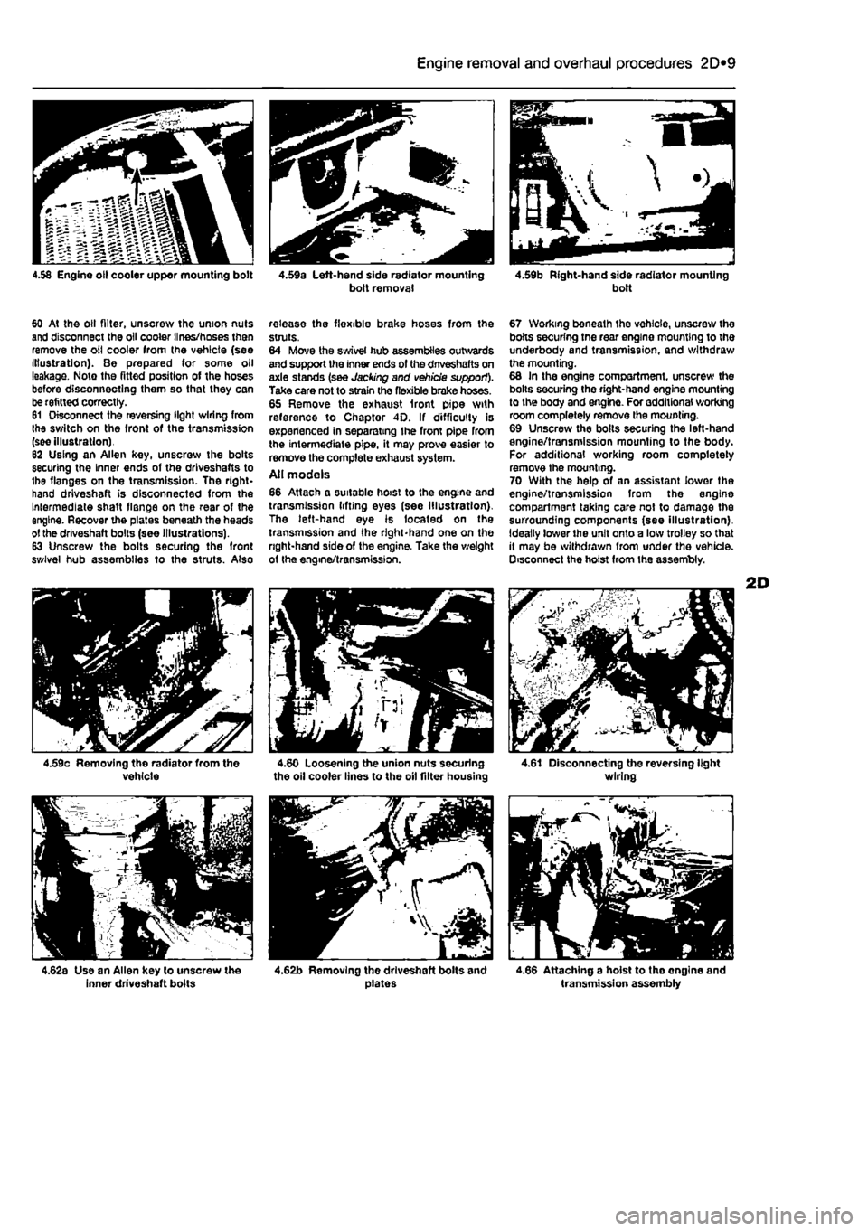
release the flexible brake hoses from the struts. 64 Move the swivel hub assemblies outwards and support the inner ends of the dnveshafts on axle stands (see Jacking and vehicle support). Take care not to strain the flexible brake hoses. 65 Remove the exhaust front pipe with reference to Chaptor 4D. If difficulty is expenenced in separating Ihe front pipe from the intermediate pipe, it may prove easier to remove the complete exhaust system. Ail models 66 Attach a suitable hoist to the engine and transmission lifting eyes (see illustration). The left-hand eye is located on the transmission and the right-hand one on the right-hand side of the engine, Take the weight of the engine/transmission.
4.60 Loosening the union nuts securing the oil cooler lines to the oil filter housing
4.62b Removing the driveshaft bolts and plates
67 Working boneath the vehicle, unscrew the bolts securing tne rear engine mounting to the underbody and transmission, and withdraw the mounting. 68 In the engine compartment, unscrew the bolts securing the right-hand engine mounting to the body and engine. For additional working room completely remove the mounting. 69 Unscrew the boils securing the left-hand engine/transmission mounting to the body. For additional working room completely remove Ihe mounting. 70 With the help of an assistant lower the engine/transmission from the engino compartment taking care not to damage the surrounding components (see illustration). Ideally lower the unit onto a low trolley so that it may be withdrawn from under the vehicle. Disconnect the hoist from ihe assembly.
4.61 Disconnecting the reversing light wiring
4.66 Attaching a hoist to tho ongine and transmission assembly
Page 111 of 225
2D*10 Engine removal and overhaul procedures
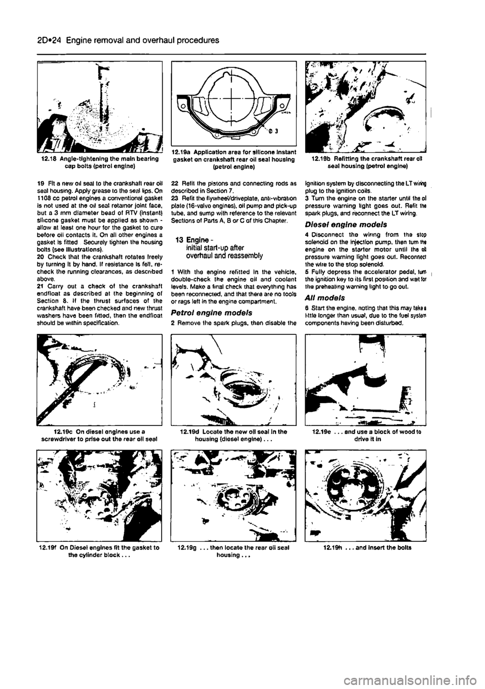
12.18 Angle-tightening the main bearing cap bolts (petrol engine)
12.Ida Application area for silicone Instant gasket on crankshaft rear oil seal housing (petrol engine) 12.19b Refitting the crankshaft rear oil seal housing (petrol engine)
19 Fit a new oil seal to the crankshaft rear oil seal housing. Apply grease to the seal lips. On 1108 cc petrol engines a conventional gasket Is not used at the oil seal retainer joint face, but a 3 mm diameter bead of RTV (Instant) silicone gasket must be applied as shown -allow at least one hour 1or the gasket to cure before oil contacts it. On all other engines a gasket Is fitted Securely tighten the housing bolts (see Illustrations). 20 Check that Ihe crankshaft rotates freely by turning It by hand. If resistance Is fell, re-check the running clearances, as described above. 21 Carry out a check of the crankshaft endfloat as described at the beginning of Section 8. If the thrust surfaces of the crankshaft have been checked and new thrust washers hove been fitted, then the endfioat should be within specification.
22 Refit the pistons and connecting rods as described in Section 7. 23 Refit the flywheeVdriveplate, and-vibration plate (16-valvo engines), oil pump and pick-up tube, and sump with reference to the relevant Sections of Parts A, B or C of this Chapter.
13 Engine -initial start-up after overhaul and reassembly
1 With the engine refitted In the vehicle, double-check the engine oil and coolant levels. Make a final check that everything has been reconnected, and that there are no tools or rags left In the engine compartment.
Petrol engine models 2 Remove the spark plugs, then disable the
ignition system by disconnecting the LT wiring plug to the ignition colls. 3 Turn the engine on the starter until Ihe oi pressure warning light goes out. Refit ihe spark plugs, and reconnect the LT wiring.
Diesel engine models 4 Disconnect tho wiring from the stop solenoid on the Injection pump, then turn the engine on the starter motor until the oil pressure warning light goes out. Reconnect ihe wire to the stop solenoid. 6 Fully depress the accelerator pedal, turn tho ignition key to its first position and wait tor HHJ preheating warning light to go out.
All models 6 Start the engine, noting that this may take i little longer than usual, due to the fuel system components having been disturbed.
12.19c On diesel engines use a screwdriver to prise out the rear oil seal 12.19d Locate the new oil soalln the housing (diosel engine)... 12.19e ... and use a block of wood to drive it in
12.19f On Diesel engines fit the gasket to the cylinder block ... 12.19g ... then locate the rear oli seal housing... 12.19h ... and Insert the bolts
Page 124 of 225
4A*2 Fuel system - single-point petrol Injection models
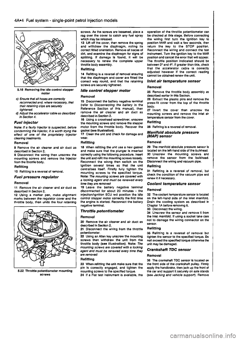
motor c) Ensure that all hoses are correctly reconnected and, where necessary, that their retaining clips are securely tightened. d) Adjust the accelerator cable as described In Section 4.
Fuel injector Note: If a faulty Injector Is suspected, before condemning the Injector, it is worth vying the effect of one of the proprietary Injector cleaning treatments. Removal 8 Remove the air cleaner and air duct as described In Section 2. 9 Disconnect the wiring then unscrew the mounting screws and remove Ihe Injector from the throttle body. Refitting 10 Refitting is a reversal of removal.
Fuel pressure regulator
Removal 11 Remove Ihe air cleaner and air duel as described In Section 2. 12 Using a marker pen. make alignment marks between the regulator cover end the throttle body, then undo the four retaining
screws. As the screws are loosened, place a rag over the cover to catch any fuel spray which may be released. 13 Lift off the cover, then remove the spring and withdraw the diaphragm, noting Its correct fitted orientation. Remove all traces of dirt, and examine the diaphragm for signs of splitting. If damage Is found, it will be necessary to renew the complete upper throttle body assembly. Refitting 14 Refitting is a reversal of removal ensuring that the diaphragm and cover are fitted the correct way round, and that the retaining screws are securely tightened,
Idle control stepper motor
Removal 15 Disconnect the battery negative terminal (refer to Disconnecting the battery In the Reference Section of this manual), then remove the air cleaner and air duct as described in Section 2. 16 Using a crosshead screwdriver, unscrew the mounting screws and remove the stepper motor from the throttle body. Recover the gaskei (see illustration). 17 Clean the unit and check for damage and wear. Refitting 18 When refitting the unit use a new gasket and make sure that the plunger is inserted correctly using the following procedure. Insert the unit and refit the mounting screws loosely. Reconnect the wiring then switch on the ignition several times so that the unit centralises itself. Finally fully tighten the mounting screws to the specified torque. Note: The mounting screws are covered with a locking agent and must be renewed every time they are removed 19 Leave the battery negative terminal disconnected for about 20 minutes - the injection/ignition ECU will position the Idle control stepper motor correctly the first time the engine is started. Reconnect the battery negative terminal.
Throttle potentiometer
Removal 20 Remove the air cleaner and air duct as described in Section 2. 21 Disconnect the wiring from the throttle potentiometer. 22 Using an Allen key unscrew the mounting screws then withdraw the unit from the throttle body (see Illustration). Note: The mounting screws ere covered with a locking agent and must be renewed every time they are removed. Refitting 23 When refitting the unit make sure that the pin Is correctly engaged, and tighten the mounting screws to the specified torque. 24 If a Rat test Instrument is available, the
operation of the throttle potentiometer can be checked at this stage. Before connecting the wiring first turn Ihe ignition key to position MAR and wait a few seconds, then return the key to the STOP position, Reconnect the wiring and connect the test instrument. Turn the Ignition key to the MAR position and cancel the error that will appear. The throttle position Indicated should be between 0° and 4°. If greater than this, check thai the accelerator cable is correctly adjusted however If the correct reading cannot be obtained renew the unit.
Inlet air temperature sensor
Removal 25 Remove the throtlle body assembly as described earlier In this Section. 28 Extract the plastic pins and remove the press-fit cover from the top of the throttle body. 27 Invert the cover then unscrew the mounting screws and remove the Inlet air temperature sensor from the cover. Refitting 28 Refining Is a reversal of removal.
Manifold absolute pressure (MAP) sensor
Removal 29 The manifold absolute pressure sensor is located on the left-hand side of the bulkhead. 30 Unscrew the mounting screws and remove the sensor from the bulkhead, Disconnect the wiring and vacuum pipe. Refitting 31 Refitting is a reversal of removal, but check the condition of the vacuum pipe and renew it if necessary.
Coolant temperature sensor
Removal 32 The coolant temperature sensor Is located on the left-hand side of the inlet manifold. Drain the cooling system as described In Chapter 1A before removing it. 33 Disconnect the wiring. 34 Unscrew the sensor and remove It from the Inlet manifold. If using a socket take care not to damage Ihe wiring connector on the sensor. Refitting 35 Refitting Is a reversal of removal bui tighten Ihe sensor to the specified torque. Do not exceed the specified torque otherwise the unit may be damaged.
Crankshaft TDC sensor
Removal 36 The crankshaft TDC sensor Is located on the front side of the crankshaft pulley. Firmly apply the handbrake, then jack up the front of the car Bnd support It securely on axle stands (see Jacking end vehicle support). Remove 5.22 Throttle potentiometer mounting screws
Page 151 of 225
5A«2 Starting and charging systems
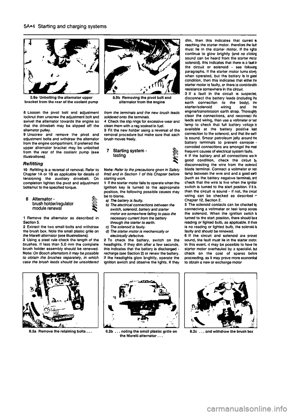
5.9a Unbolting the alternator upper bracket from the rear of the coolant pump
fl Loosen the pivot bolt and adjustment locknut then unscrew the adjustment bolt and swivel the alternator towards the engine so that the drivebefi may be slipped off the alternator pulley. 9 Unscrew and remove the pivot and adjustment bolts and withdraw the alternator Irom the engine compartment. If preferred the upper alternator bracket may bo unbolted from the rear of the coolant pump {see illustrations).
Refitting 10 Refitting is a reversal ot removal. Refer to Chapter tA or 1B as applicable for details of tensioning the auxiliary drivebeit. On completion lighten the pivot and adjustment botts/nut to the specified torque.
6 Alternator -brush holder/regulator module renewal
%
1 Remove the alternator as described in Section 5. 2 Extract the two small bolts and withdraw the brush box. Note the small plastic grille on the Marelli alternator (see illustrations), 3 Using a steol rule chock the length of the brushes. If less than 5.0 mm the complete brush holder assembly should be renewed. Note: On Bosch alternators it may be possible to obtain the brushes separate//, in which case the brush ieads should be unsoldered
5.9b Removing the pivot bolt and alternator from the engine
from ihe terminals and the new brush leads soldered onto the terminals. 4 Check the slip rings for excessive wear and clean them with a rag soaked in fuel. 5 Pit the new holder using a reversal of the removal procedure but make sure that each brush moves freely.
7 Starting system • & testing
Note: Refer to Ihe precautions given In Safety firstI and in Section I of this Chapter before stoning work. 1 If the starter motor falls to operate when the Ignition key Is turned to the appropriate position, the following possible causes may be to blame. aj The battery is faulty. b) The electrical connections between the switch, solenoid, battery and starter motor are somewhere failing to pass the necessary current from the battery through the starter to earth. c) 77:© solenoid is faulty. d) The starter motor is mechanically or electrically defective. 2 To check the battery, switch on the headlights. If they dim after a few seconds, this indicates that the battery is discharged -recharge (see Section 2) or renew the battery. If the headlights glow brightly, operate the ignition switch and observe the lights. If they
dim, then this indicates that current it reaching the starter motor, therefore the iao8 must lie In the starter motor. If the lights continue to glow brightly (and no clicking sound can be heard from the starter motor solenoid), this indicates that there is a lairt
In
the circuit or solenoid - see following paragraphs, if the starter motor turns siowfy when operated, but the battery is In good condition, then this indicates that either lae starter motor is faulty, or there is considers resistance somewhere in the circuit. 3 If a fault in the circuit is suspected, disconnect the battery ieads (including ihe earth connection to the body), lt» starter/solenoid wiring and tne engine/transmission earth strap. ThoroygWy clean the connections, and reconnect the leads and wiring, ihen use a voltmeter or J«i lamp to check that full battery voltage is available at the battery positive lead connection to the solenoid, and that the earth is sound. Smear petroleum jelly around ttie battory terminals to prevent corrosion > corroded connections are amongst the most frequent causes of electrical system faults. 4 If the battery and all connections are in good condition, check the circuit disconnecting the wire from the solenod blade terminal. Connect a voltmeter or less lamp between the wire end and a good earth (such as the battery negative terminal), ais check that the wire is live when tne ignition switch is turned to the start position. If It is. then the circuit is sound - if not. the circut wiring can be checked as described Chapter 12. Section 2. 5 The solenoid contacts can be checked
Oy
connecting a voltmeter or test lamp across Ihe solenoid. When the ignition switch is turned to the start position, there should b»a reading or lighted bulb, as applicable. II thars is no reading or lighted bulb, the solenoid is faulty and should be renewed. 6 If the circuit and solenoid are proves sound, the fault must lie in the starter motor. In this event, it may be possible to have tre starter motor overhauled by a specialist, but check on the cost of spares before proceeding, as It may prove more economical to obtain a new or exchange motor
Page 165 of 225
7A«4 Manual transmission
33 Remove lha air cleaner front section and air ducting with reference to Chapter 4C. Also disconnect the injection pump vacuum pipe from the clips on the left-hand end of the cylinder head. This work is necessary in order to fit the engine hoist 34 Support the weight of the engine using a hoist attached to the engine lifting eyes, or alternatively use a trolley Jack and block of wood beneath the engine. 35 Unscrew the nuts securing the downpipe to the exhaust manifold, then lower it and support on an axle stand. Recover the gasket. 36 Unscrew the starter motor mounting bolts and support the starter motor to one side. 37 Disconnect the wiring from the reversing light switch on the front of the transmission. 38 Unscrew the nut and disconnect the earth cable from its stud. 39 Trace the wiring back from the electronic speedometer sensor and disconnect the connector located on the left-hand side ot the engine. If a mechanical speedometer Is fitted unscrew the knurled collar and disconnect the cabte from the transmission. 40 Unbolt and remove the transmission lower cover. 41 Using an Allen key unscrew the bolts securing the inner end of the left-hand driveshaft to the transmission flange. Remove the bolts and recover the spacer plates. Support the driveshaft on an axle stand. 42 Unscrew and remove the bolts securing the left-hand swivel hub assembly to the front suspension strut, then separate the components and support the swivel hub on an axle stand. 43 Move the swrvel hub assembly outwards and support the driveshaft away from Ihe transmission. 44 Using an Allen key unscrew the bolts securing the Inner end of the right-hand driveshaft to the intermediate shaft flange. Remove the bolts and recover the spacer plates. Support the driveshaft on an axle stand. 45 Remove the intermediate driveshaft with reference to Chapter 8. 46 Working beneath the vehicle, unscrew the bolts securing the rear engine mounting to the underbody then unscrew the bolts securing the mounting to the transmission and withdraw the mounting assembly from under the vehicle.
47 Unscrew the bolts securing the left-hand engine/transmission mounting to the body then unscrew Ihe bolts from the transmission and remove the mounting. 48 Support the weight of the transmission on a trolley jack then unscrew the remaining nut and bolts from the bellhousing and pull the transmission away from the engine.
A
Warning: Support the trans-mission to ensure that It remains steady o/i the jack head. Keep the transmission level until the Input shaft
1$
fully withdrawn from the clutch friction plate.
Refitting 48 Refitting is a reversal of the removal procedure, but note the following points. a) Appiy a smear* of high-meiting-point grease to the clutch friction piate splines; take care to avoid contaminating the friction surfaces. b) Tighten all bolts to the specified torque. c) Fit new clips to secure the driveshaft gaiters to the transmission output shafts. d) Adjust the clutch cable (where applicable) as described In Chapter 6.
4 Manual transmission overhaul -general Infomtatlon
Overhauling a manual transmission is a difficult and Involved Job for the DIY home mechanic. In addition to dismantling and reassembling many small parts, clearances must be precisely measured and, if necessary, changed by selecting shims and spacers. Internal transmission components are also often difficult to obtain, and in many Instances, extremely expensive. Because of this, If the transmission develops a fault or becomes noisy. Ihe best course of action is to have the unit overhauled by a specialist repairer, or to obtain an exchange reconditioned unit. Nevertheless, it is not impossible for the more experienced mechanic to overhaul the transmission, provided the special tools are available, and the Job is done in a deliberate step-by-step manner, so that nothing is overlooked.
The tools necessary for an overhaul include internal and external clrclip pliers, bearing pullers, a slide hammer, a sat of pin punches, a dial test Indicator, and possibly a hydraulic press. In addition, a large, sturdy workbench 8od a vice will be required. During dismantling o1 the transmission, make careful notes of how each component
1$
fitted, to make reassembly easier and more accurate. Before dismantling the transmission, it will help if you have some idea what area is malfunctioning. Certain problems can be closely related to specific areas In the transmission, which can make component examination and replacement easier. Refer to the Fault Finding Section at the end of this manual for more Information.
5 Reversing light switch -testing, removal and refitting ||
Testing 1 The reversing light circuit is controlled by a plunger-type switch screwed into the front of the transmission casing. If a fault develops, first ensure that Ihe circuit fuse has not blown. 2 To test the switch, disconnect the wiring connector, and use a multimeter (set to the resistance function) or a battery-and-bulb test circuit to check that there is continuity between the switch terminals only when reverse gear is selected. If this is not the case, and there are no obvious breaks or other damage to the wires, the switch is faulty, and must be renewed.
Removal 3 Access to the reversing light switch Is best achieved from under the vehicle. Apply the handbrake then jack up Ihe front of the vehicle and support on axle stands (see Jacking and vehicle support). 4 Disconnect the wiring connector, then unscrew It from the transmission casing.
Refitting 5 Refit the switch and tighten securely. 6 Reconnect the wiring then lower the vehicle to the ground.
Page 167 of 225
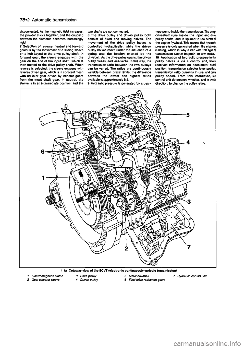
7B*2 Automatic transmission
disconnected. As the magnetic field increases, the powder sticks together, and the coupling between Ihe elements becomes Increasingly rigid. 7 Selection of reverse, neutral and forward gears is by the movement of a sliding sleeve on a hub keyed to the drive pulley shaft. In forward gear, the sleeve engages with the gear on the end of the input shaft, which is then locked to the drive pulley shaft. When reverse is selected, the sleeve engages with reverse driven gear, which is in constant mesh with an idler gear driven by transfer gears from the input shaft gear. In neutral, the sleeve Is in an intermediate position, and the
two shafts are not connected. 8 Tho drive pulley and driven pulley both consist of fixed and moving halves. The movement of ihe drive pulley halves is controlled hydraulically, while the driven pulley halves move under the influence of a spring and the tension exerted by the drivebeit. As the drive pulley opens, the driven pulley closes, and vice-versa. In this way, the transmission ratio between the two pulleys can be varied. The ratios are continuously variable between preset limits; the difference between the lowest and highest ratios available is approximately 5:1. 9 Hydraulic pressure is generated by a gear-
type pump Inside the transmission. The punp driveshaft runs inside the Input and drive pulley shafts, and Is splined to the centred the engine flywheel. This means that hydreulc pressure is only generated when the engine is running, which is why a car with this type ot transmission cannot be push- or tow-started 10 Application of hydrautic pressure to the pulley halves is via a control unit, which receives information on accelerator pedal position, transmission selector lever position, transmission ratio currently in use, and drive pulley speed. From this information, the control unit determines whether, and in which direction, lo change the pulley ratios.
1.1 a Cutaway view of the ECVT (electronic continuously variable transmission) 7 Electromagnetic dutch 3 Drive pulley 5 Metal drivebeit 7 Hydraulic controt unit 2 Gear selector sleeve A Dnven pulley 6 Final drive reduction gears
Page 171 of 225
7B*6 Automatic transmission
Gear selector cable -adjustment
1 Remove the battery and tray as described In Chapter 5A for access to the transmission. 2 Disconnect the selector cable from the lever on Ihe transmission. 3 Move the selector fever inside the vehicle to the N (Neutral) position, then move the lever on the transmission to Its central (Neutral) position. Locate the cable end over the lever. If the cable end fitting does not line up exactly with the hole In Ihe lever, loosen the adjustment nut and reposition the end fitting. 4 With the adjustment correct reconnect tha cable to the lever, then move the selector lever to the P (Park) position. Check that the lever on the transmission has also moved to the P position. 6 Refit the battery and tray as described in Chapter 5A. 6 Road test the vehicle, and check for correct operation in all selector lever positions.
9 Gear selector cable -removal and refitting at
7 Inside the vehicle disconnect the selector cable from the bottom of the selector lever (hen remove it from the support bracket, a Withdraw the cable into the engine compartment, and remove it.
Refitting 9 Refitting is a reversal of removal, but adjust the cable as described in Section 8. 10 Check that It is only possible to start the engine in positions P and N. Reposition the selector lever switch If necessary. 11 Road test the vehicle, and check for correct operation In ell selector lever positions.
10 Transmission oil pump - & mnvtiifll rAtiMlitA removal a/id refitting
Removal 1 Using an Allen key. unscrew the screw and remove the selector lever knob from the lever. 2 Remove the oddment tray and the ashtray. 3 Remove the screws and withdraw the centre console and selector mechanism cover. 4 Unscrew the mounting screws, slightly lift the centre console, then disconnect the wiring and remove the console, 5 Remove the battery and tray as described in Chapter 5A for access to the transmission, 6 Disconnect the selector cable from the lever on the transmission.
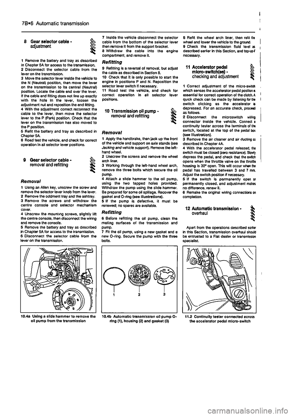
Removal 1 Apply the handbrake, then lack up the front of the vehicle and support on axle stands (see Jacking and vehicle support). Remove the left-hand wheel. 2 Unscrew the screws and remove the wheel arch liner. 3 Working through the left-hand wheel arch, remove Ihe three bolts which secure the oil pump. 4 Attach a slide hammer to the oil pump, using the two tapped holes provided. Withdraw the pump using the slide hammer. Be prepared for some oil spillage. Recover the gasket end O-ring (see illustrations). 5 If the pump is defective, it must be renewed; no spares are available.
Refitting 6 Before refitting Ihe oil pump, clean Ihe mating surfaces of the transmission and pump. 7 Rt the oil pump, U9ing a new gasket and a new O-ring. Secure the pump with the three bolts.
8 Refit the wheel arch liner, then refit tto wheel and lower the vehicle to the ground. 9 Check the transmission fluid level » described earlier in this Section, and top-upif necessary.
11 Accelerator pedal & mfcro-Bwftcb(es) -checking
and
adjustment ^
1 Correct adjustment of the micro-awtlch which senses the accelerator pedal position s essential for correct operation of the clutch.
A
quick check can be made by listening for the switch clicking as the accelerator a depressed. For an accurate check, proceed as follows. 2 Disconnect Ihe mlcroswitch wiring connector (nside the vehicle. Connect a continuity tester across the terminals of the switch, located at the top of (he pedal box (see Illustration}. 3 Remove the air cleaner and air ducting as described in Chapter 4A. 4 With the accelerator pedal releassd, th« switch must be closed (zero resistance). Slowty depress the pedal, and check that the switch opens when the throttle valve on the throttle housing is 30° open. This will occur when the pedal has travelled between 3 and 7 mm. Adjust the switch position if necessary. 5 If the switch is permanently open or permanently closed, and adjustment makes no difference, renew ft. 6 Remake the original wiring connections on completion,
12 Automatic transmission -overhaul
Apart from the operations described earlier in this Section, transmission overhaul should be entrusted to a Rat dealer or transmission specialist.
10.4a Using a slide hammer to remove the oil pump from the transmission 10.4b Automatic transmission oil pump O-dng (1), housing (2) and gasket (3) 11.2 Continuity tester connected ecross the accelerator pedal micro-switch