service FIAT PUNTO 1998 176 / 1.G Owner's Manual
[x] Cancel search | Manufacturer: FIAT, Model Year: 1998, Model line: PUNTO, Model: FIAT PUNTO 1998 176 / 1.GPages: 225, PDF Size: 18.54 MB
Page 160 of 225

Clutch 6*3
6 WorWng inside the vehicle, extract the split pin and remove the washer securing the master cylinder pushrod to the clutch pedal. Dsoonnect the pushrod from the pivot. 7 Have an assistant support the master cylinder In the engine compartment, then unscrew the mounting bolts. Withdraw the master cylinder from the engine compartment, 8 II is not possible to obtain an overhaul kit from Flat however some motor factors may be abls to supply one. Follow the Instructions with the repair kit if obtained.
Refitting 9 Refit the clutch master cylinder by following ihe removal procedure In reverse, noting the following. a) Apply a
Utile
high-melting point grease to the clutch pedal pivot. b) Tighten the mounting bolts and union nut securely. cj Fit a new split pin to the pushrod. d) Where removed, refit the alternator
as
described In Chapter 5A e) On completion bleed the clutch hydraulic system as descnbed in Section
A.
7 Clutch assembly -
removal,
inspection
and
refitting
S Clutch slave cylinder-removal and refitting
Note: This procedure applies to models fitted
ivrth
the hydraulically-operated clutch release mechanism. Note: Refer to the warning at the beginning
of
Section A regarding the hazards of working
with
hydraulic fluid.
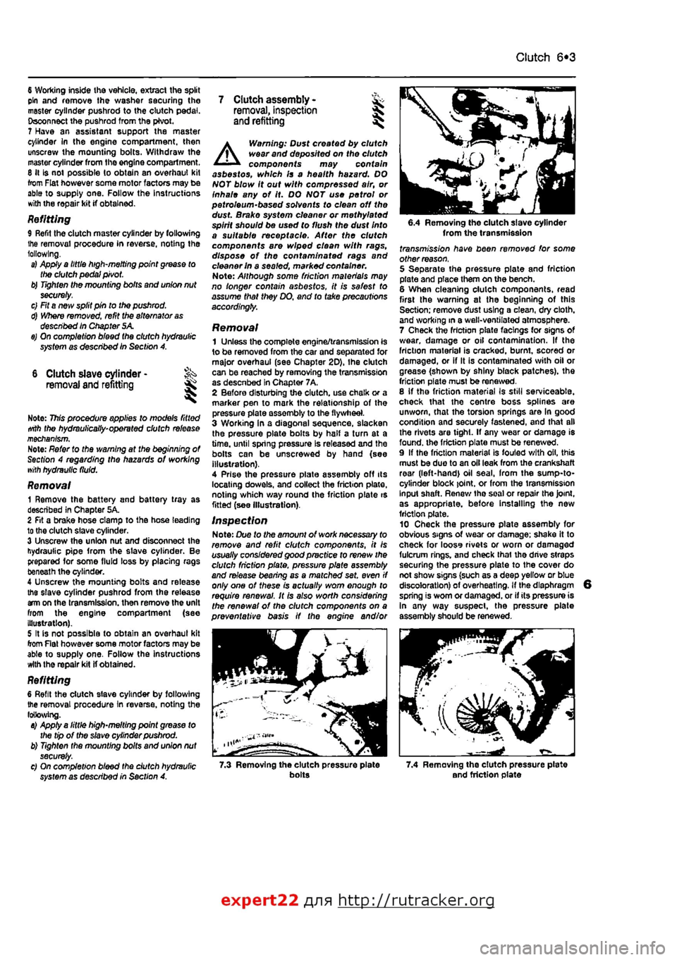
Removal 1 Remove the battery and battery tray as described in Chapter 5A. 2 Fit a brake hose clamp to tha hose leading to the clutch slave cylinder. 3 Unscrew the union nut and disconnect the hydraulic pipe from the slave cylinder. Be prepared for some fluid loss by placing rags beneath the cylinder. 4 Unscrew the mounting bolts and release the slave cylinder pushrod from the release am on the transmission, then remove the unit from the engine compartment (see Illustration). 5 It is not possible to obtain an overhaul kit from Flat however some motor factors may be able to supply one. Follow tha instructions with the repair kit if obtained.
Refitting 6 Refit the clutch slave cylinder by following the removal procedure In reverse, noting the following. a) Apply a little high-melting point grease to the tip of the slave cylinder pushrod. b) Tighten the mounting bolts and union nut securely. c) On completion bleed the dutch hydraulic system as described in Section A.
A
Warning: Dust created by clutch wear and deposited on the clutch components may contain asbestos, which Is a health hazard. DO NOT blow it out with compressed air, or inhale any of it. DO NOT use petrol or petroleum-based solvents to clean off the dust. Brake system cleaner or methylated spirit should be used to flush the dust Into a suitable receptacle. After the clutch components are wiped clean with rags, dispose of the confam/nafed rags and cleaner In a sealed, marked container. Note: Although some friction materials may no longer contain asbestos, it is safest to assume that they DO. and to take precautions accordingly.
Removal 1 Unless the complete engine/transmission is to be removed from the car and separated for major overhaul (see Chapter 2D), Ihe clutch can be reached by removing the transmission as descnbed in Chapter 7A, 2 Before disturbing the clutch, use chalk or a marker pen to mark the relationship of the pressure plate assembly to the flywheel. 3 Working In a diagonal sequence, slacken the pressure plate bolts by half a turn at a time, until spring pressure Is released and the bolls can be unscrewed by hand (see Illustration). 4 Prise the pressure piate assembly off its locating dowels, and collect the friction plate, noting which way round the friction plate is fitted (see Illustration).
Inspection Note: Due to the amount of work necessary to remove and refit clutch components, It is usually considered good practice to renew the clutch friction plate, pressure plate assembly and release bearing as a matched set. even if only one of these is actually worn enough to require renewal. It Is also worth considering the renewal of the clutch components on a preventative basis if the engine and/or
6.4 Removing the clutch slave cylinder from the transmission fransmj'ss/on have been removed for some other reason. 5 Separate the pressure plate and friction plate and place them on the bench. 6 When cleaning clutch components, read first the warning at the beginning of this Section; remove dust using a clean, dry cloth, and working in a well-ventilated atmosphere. 7 Check the friction plats facings for signs Of wear, damage or oil contamination. If the friction material is cracked, burnt, scored or damaged, or if It is contaminated with oil or grease (shown by shiny black patches), the friction plate must be renewed. 8 If tho friction material Is still serviceable, check that the centre boss splines are unworn, that the torsion springs are In good condition and securely fastened, and that all the rivets are tight. If any wear or damage is found, the friction plate must be renewed. 9 If the friction material is fouled with oil, this must be duo to an oil leak from the crankshaft rear (left-hand) oil seal, from the sump-to-cytinder block joint, or from the transmission Input shaft. Renew tha soal or repair the Joint, as appropriate, before Installing the new friction plate. 10 Check tha pressure plate assembly for obvious signs of wear or damage; shake it to check for looss rivets or worn or damaged fulcrum rings, and check thai the drive straps securing the pressure plate to the cover do not show signs (such as a deep yellow or blue discoloration) of overheating. If the diaphragm spring is worn or damaged, or if its pressure is In any way suspect, the pressure plate assembly should be renewed.
7.3 Removing the clutch pressure plate bolts 7.4 Removing the clutch pressure plate and friction plate
expert22 {
a http://rutracker.org
Page 175 of 225

I
8*4 Driveshafts
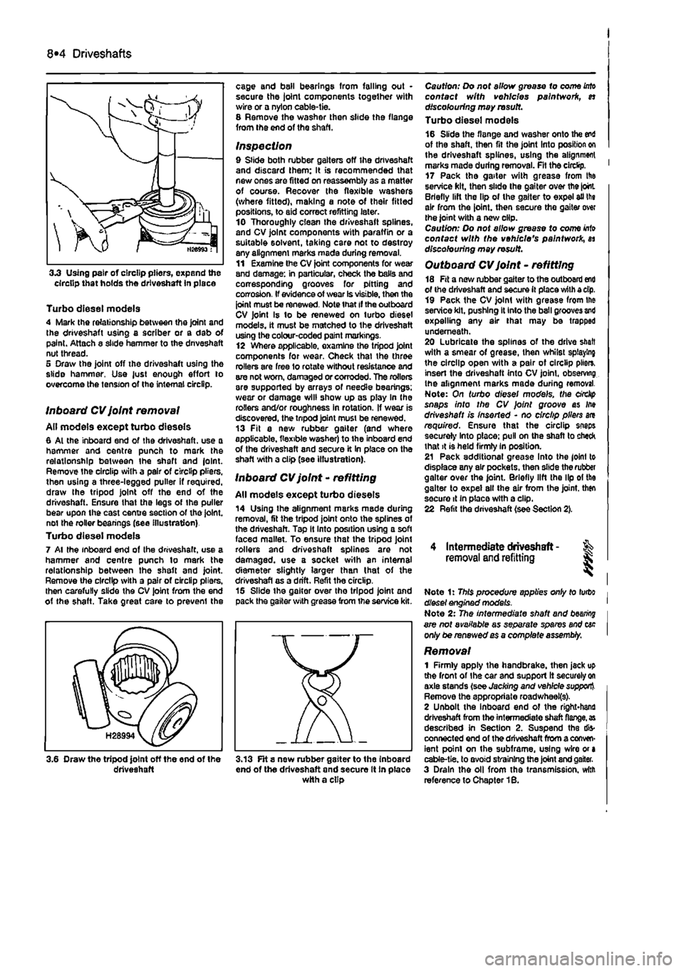
3.3 Using pair of circlip pliers, expand the circlip that holds the driveshaft in place
Turbo diesel models 4 Mark the relationship between the joint and the driveshaft using a scriber or a dab of paint. Attach a slide hammer to the dnveshaft nut thread. 5 Draw the joint off the driveshaft using the slide hammer, Use just enough effort to overcome the tension of the internal circlip.
Inboard CV joint removal All models except turbo dieseis 6 Al the inboard end of the driveshaft. use a hammer and centre punch to mark the relationship between Ihe shaft and |olnt. Remove the circlip with a pair of circlip pliers, then using a three-legged puller if required, draw Ihe tripod joint off the end of the driveshaft. Ensure that the legs of Ihe puller bear upon the cast centre section of the joint, not the roller beanngs (see illustration) Turbo diesel models 7 Al the inboard end of Ihe driveshaft. use a hammer and centre punch lo mark the relationship between the shaft and joint. Remove the circlip with a pair of circlip pliers, then carefully slide the CV joint from the end ot the shaft. Take great care to prevenl the
cage and bail bearings from falling out • secure the joint components together with wire or a nylon cable-tie. 8 Remove the washer then slide the flange from the end of the shaft.
Inspection 9 Slide both rubber gaiters off the driveshaft and discard them: It is recommended that new ones are fitted on reassembly as a matter of course. Recover the flexible washers (where fitted), making a note of their fitted positions, to aid correct refitting later. 10 Thoroughly clean the driveshaft splines, and CV joint components with paraffin or a suitable solvent, taking care not to destroy any alignment marks made during removal. 11 Examine Ihe CV joint components for wear and damage: in particular, check the balls and corresponding grooves for pitting and corrosion. If evidence of wear Is visible, then the joint must be renewed. Note that if the outboard CV joint Is to be renewed on turbo diesel models, it must be matched to the driveshaft using the colour-coded paint markings. 12 Where applicable, examine the tripod joint components for wear. Check thai the three rollers are free lo rotate without resistance and are not worn, damaged or corroded. The rollers are supported by arrays of needle bearings: wear or damage will show up as play In the rollers and/or roughness in rotation. If wear is discovered, the tnpod joint must be renewed. 13 Fit a new rubber gaiter (and where applicable, flexible washer) to the inboard end of the driveshaft and secure it In place on the shaft with a clip (see illustration).
Inboard CV joint - refitting
All models except turbo dieseis 14 Using Ihe alignment marks made during removal, fit the tripod joint onto the splines of the driveshaft. Tap It Into position using a soft faced mallet. To ensure that the tripod Joint rollers and driveshaft splines are not damaged, use a socket with an internal diameter slightly larger than I hat of the driveshafl as a drift. Refit the circlip. 15 Slide the gaiter over tho tripod joint and pack the gaiter with grease from the service kit.
3.6 Draw the tripod joint off the end of the driveshaft 3.13 FH s new rubber gaiter to the inboard end of the driveshaft and secure It in place with a clip
Caution: Do not allow grease to come
into
contact with vehicles paintwork, es discolouring may rasutt. Turbo diesel models 16 Slide the flange and washer onto the end of the shaft, then fit the joint Into position on the driveshaft splines, using the alignment marks made during removal. Fit the circlip. ' 17 Pack the gaiter with grease from His service kit, then slide the gaiter over the joint. Briefly lift the lip of the gaiter to expel ail the air from the joint, then secure the gaiter over the joint with a new clip. Caution: Do not allow grease to come
Into
contact with the vehicle's paintwork, as discolouring may result.
Outboard CV joint - refitting 18 Fit a new rubber gaiter to the outboard end of the driveshaft and secure it place with a dp, 19 Pack the CV joint with grease from Ihe service kit, pushing It into the ball grooves and expelling any air that may be trapped underneath. 20 Lubricate the splines of the drive shaft with a smear of grease, then whilst splaying the circlip open with a pair ot circlip pile*, insert the driveshaft into CV joint, observing the alignment marks made during removal. Note: On turbo diesel models, the circlip snaps into the CV Joint groove as Ifte driveshaft is inserted - no circlip pliers are required. Ensure that the circlip snaps securely Into place: pull on the shaft to check that it is held firmly In position. 21 Pack additional grease Into the joint to displace any air pockets, then slide the rubber gaiter over the joint. Briefly lift the lip ol the gaiter to expel all the air from Ihe joint, then secure it In place with a clip. 22 Refit the driveshaft (see Section 2).
4 Intermediate driveshaft - % removal and refitting J;
Note 1: This procedure applies only to turbo diesel engined models. Note 2: The intermediate shaft and
bearing
are not available as separate spares and cac only be renewed as a comptefe assembly.
Removal 1 Firmly apply the handbrake, then jack up the front of Ihe car and support It securely
on
axle stands (see Jacking and vehicle support). Remove the appropriate roadwheei(s). 2 Unbolt the inboard end of the right*hand driveshaft from the intermediate shaft
flange, as
described In Section 2. Suspend the dis-connected end of the driveshaft from a conven-ient point on the subframe, using wire or a cable-tie. to avoid straining the joint and gaiter. 3 Drain the oil from the transmission, with reference to Chapter 1B.
Page 179 of 225

Braking system 9®3
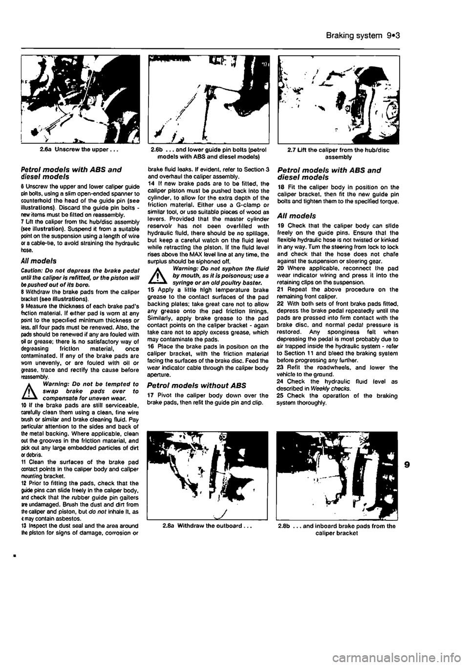
2.6a Unscrew the upper...
Petrol models with ABS and diesel models 6 Unscrew the upper and lower caliper guide cin bolts, using a slim open-ended spanner to counterhold the head of the guide pin (see illustrations). Discard the guide pin bolts -new items must be fitted on reassembly. 7 Lift the caliper from the hub/disc assembly (see illustration). Suspend it from a suitable point on the suspension using a length of wire or 8 cable-tie, to avoid straining the hydraulic hose.
All models Caution: Do not depress the brake pedal until the caliper is refitted, or the piston will
be
pushed out of Its bore. 8 Withdraw the brake pads from the caliper bracket (see illustrations). 9 Measure the thickness of each brake pad's foclion material. If either pad is worn at any point to the specified minimum thickness or less, all four pads must be renewed. Also, the pads should be renewed if any are fouled with oil or grease; there is no satisfactory way of degreasing friction material, once contaminated. If any of the brake pads are worn unevenly, or are fouled with oil or grease, trace and rectify the cause before reassembly.
A
Warning: Do not be tempted to swap brake pads over to compensate for uneven wear. 10 if the brake pads are still serviceable, carefully clean them using a clean, fine wire brush or similar and brake cleaning fluid. Pay particular attention to the sides and back of the metal backing. Where applicable, clean out the grooves in the friction material, and pick out any large embedded panicles of dirt
or
debris. 11 Clean the surfaces of the brake pad contact points In the caliper body and caliper mounting bracket. 12 Prior to fitting the pads, check that the giide pins can slide freely in the caliper body, and check that the rubber guide pin gaiters
are
undamaged. Brush the dust and din from
the
caliper and piston, but do not inhale it. as
4 may
contain asbestos. 13 Inspect the dust seal and the area around Ihe piston for signs of damage, corrosion or
models with ABS and diesel models)
brake fluid leaks. If evident, refer to Section 3 and overhaul the caliper assembly. 14 If new brake pads are to be fitted, the caliper piston must be pushed back into the cylinder, to allow for the extra depth of the friction material. Either use a G-clamp or similar tool, or use suitable pieces of wood as levers. Provided that the master cylinder reservoir has not oeen overfilled with hydraulic fluid, there should be no spillage, but keep a careful watch on the fluid level while retracting the piston. If the fluid level rises above the MAX level line at any time, the surplus should be siphoned off. A Warning: Do not syphon the fluid by mouth, as it is poisonous; use a syringe or an old poultry baster. 15 Apply a little high temperature brake grease to the contact surfaces of the pad backing plates: take great care not to allow any grease onto the pad friction linings. Similarly, apply brake grease to the pad contact points on the caliper bracket - again take care not to apply excess grease, which may contaminate the pads. 16 Place the brake pads in position on the caliper bracket, with the friction material facing the surfaces of the brake disc. Feed the wear indicator cable through the caliper body aperture.
Petrol models without ABS 17 Pivot the caliper body down over the brake pads, then refit the guide pin and clip.
2.7 Lift the caliper from the hub/disc assembly
Petrol models with ABS and diesel models 18 Fit the caliper body in position on the caliper bracket, then fit the new guide pin bolts and tighten them to the specified torque.
AH models 19 Check that the caliper body can slide freely on the guide pins. Ensure that the flexible hydraulic hose is not twisted or kinked In any way. Turn the steering from lock to lock and check that the hose does not chafe against the suspension or steering gear. 20 Where applicable, reconnect the pad wear indicator wiring and press it into the retaining clips on the suspension. 21 Repeat the above procedure on the remaining front caliper. 22 With both sets of front brake pads fitted, depress the brake pedal repeatedly until the pads are pressed into firm contact with the brake disc, and normal pedal pressure is restored. Any sponginess felt when depressing the pedal is most probably due to air trapped inside the hydraulic system - refer to Section 11 and bleed the braking system before progressing any further. 23 Refit the roadwheels. and lower the vehicle to the ground. 24 Check the hydraulic fluid level as described in Weekly checks. 25 Check the operation of the braking system thoroughly,
2.8a Withdraw the outboard... 2.8b ... and inboard brake pads from the caliper bracket
Page 214 of 225

10*1
Chapter 12
Body electrical systems
Contents
Bulbs (exterior lights) - renewal 4 Bulbs (interior lights) - renewal 5 Electrical fault finding - general information 2 Exterior light units - removal and refitting 6 Fuses and relays - general Information 3 General information and precautions 1 Headlight beam alignment • general Information 6 Horn • removal and refitting 9 Instrument panel - removal and refitting 7 Loudspeakers - removal and refitting 10
Degrees of difficulty
Radio aerial - removal and refitting 11 Radio/cassette player • removal and refitting 12 Speedometer drive cable - removal and refitting 13 Switches - removal end refitting 14 Tailgate wiper motor - removal and refitting 15 Windscreen wiper motor - removal and refitting 17 Windscreen/tailgate washer system components • removal and refitting 16 Wiper arm • removal and refitting 18
Easy,
statable for ^
novice with liffle
|| experience ^
Fairly
easy,
suitable for beginner with ^ some experience ^
Fabtycffficiit,
suitable
for competent ^
DIY
mechanic ^
Difficult, suitable for
^ experienced DIY JR mechanic
Very difficult,
A,
suitable
for
expert DIY
Sj or professional ^
Specifications
Bulb ratings Watts Headlights 60/55 Front long range driving light 55 Front fogllght 55 Front direction Indicator light 21 Front sidelight 5 Front direction indicator repeater light 5 Stop light 21 Tall light 5 Rear direction indicator light 21 Reversing light 21 near fogllght 21 Hear number plate light 5 Courtesy light 10 Map reading light 5
1 Genera! information and precautions
A
Warning: fie/Ore carrying out any work on the electrical system, read through the precautions given in Safety first! at the beginning of this manual, and in Chapter 8. The electrical system is of 12-volt negative earth type. Power for the lights and all electrical accessories is supplied by a lead/acid type battery, which is charged by the alternator. This Chapter covers repair and service procedures for the various electrical components not associated with the engine. Information on the battery, alternator and starter motor can be found in Chapter 5. It should be noted that, prior to working on any component In the electrical system, the
battery negative terminal should first be disconnected, to prevent the possibility of electrical short-circuits and/or fires. Caution: Before proceeding, refer to Disconnecting the battery In the Reference Section of this manual for further information.
2 Electrical fault finding-general information
Note: Refer to the precautions given In Safety first! and in Section 1 of this Chapter before starting work. The following tests relate to testing ot the main electrical circuits, and should not be used to test delicate electronic circuits (such as antHock braking systems), particularly where an electronic con fro/ module is used.
General 1 A typical electrical circuit consists of an electrical component, any switches, relays, motors, fuses, fusible links or circuit breakers related to that component, and the wiring and connectors which link the component to both the battery and the chassis. To help to pinpoint a problem in an electrical circuit, wiring diagrams are Included at the end of this manual. 2 Before attempting to diagnose an electrical fault, first study the appropriate wiring diagram, to obtain a more complete understanding of the components included In the particular circuit concerned. The possible sources of a fault can be narrowed down by noting whether other components related to the circuit are operating properly. If several components or circuits fait at one time, the problem Is likely to be related to a shared fuse or earth connection.