Reference FIAT PUNTO 1998 176 / 1.G Service Manual
[x] Cancel search | Manufacturer: FIAT, Model Year: 1998, Model line: PUNTO, Model: FIAT PUNTO 1998 176 / 1.GPages: 225, PDF Size: 18.54 MB
Page 126 of 225
4A*2 Fuel system - single-point petrol Injection models
1 The luel system referred to In this Section is defined as the tank-mounted fuel pump, the fuel litter, the throttle body and pressure regulator components, and the metal pipes and flexible hoses of the fuel lines between these components. All ihese contain fuel which will be under pressure while the engine Is running and/or while tha Ignition is switched on. The pressure will remain for some time after tho ignition has been switched off, and must be relieved before any of these components are disturbed (or servicing work. 2 Disconnect the battery negative terminal (refer to D/sconnecf/ngr the battery in the Reference Section of this manual), 3 Place a container beneath the relevant connection/union to be disconnected, and have a large rag ready to soak up any escaping fuel not being caught by the container. 4 Slowly loosen the connection or union nut (as applicable) to avoid a sudden release of pressure, and wrap tho rag around the connection to catch any fuel spray which may be expelled. Once the pressure is released, disconnect the fuel line, and Insert plugs to minimise fuel loss and prevent the entry of dirt Into the fuel system.
9 Inlet manifold -removal and refitting ^
Note: Refer to the warning given In Section 1 before proceeding.
Removal 1 Remove the throttle body assembly as described in Section 5. 2 Drain the cooling system as described in Chapter 1A. 3 Disconnect the winng connector from the coolanl temperature sensor (situated on the left-hand sidB of the manifold). 4 Undo the bolt securing the accelerator cable mounting bracket to the manifold, and position it clear of the manifold. 5 Slacken the retaining clip and disconnect tha coolant hose from the rear of the manifold. 6 Disconnect the brake vacuum hose. 7 Undo the seven manifold retaining nuts and
10.2 The diagnostic connector la located behind the ECU bolts, and remove (he manifold from the engine. Remove the gasket and discard It; a new one should be used on refitting.
Refitting 8 Refitting is a reverse of the removal procedure, noting the following points: a) Ensure that the manifold and cylinder head mating surfaces are clean and dry, and fit a nev/ manifold gasket. Refit the manifold and securely tighten Its retaining nuts. b) Ensure that all relevant hoses are reconnected fo their original positions and are securely held (where necessary) by the retaining clips. c) Refit the throttle body assembly with reference to Section S. d) On completion, refill the cooling system as described In Chapter 1A.
correctly adjusted, and that the engine breather hoses are clear and undamaged. 2 If these checks fall to reveal the cause of the problem, the vehicle should be taken to a suitably-equipped Fiat dealer for testing. A wiring block connector Is Incorporated In the engine management circuit, into which a special electronic diagnostic tester can be plugged; the connector is situated behind the ECU (see Illustration). The tester will locate the fault quickly and simply, alleviating the need to test all the system components Individually, which is a time-consuming operation that carries a high risk of damaging the ECU.
Adjustments 3 As mentioned above, the idle speed and mixture adjustment are all monitored and controlled by the ECU, and are not adjustable Experienced home mechanics with a considerable amount of skill and equipment (including a good-quality tachometer and a good-quality, carefully calibrated exhaust gas analyser) may be able to check the exhaust CO level and ihe idle speed. However, If thes* are found lo be in need of adjustment, the car must be taken to a suitably-equipped Flat dealer for testing using the special test equipment which is plugged into the diagnostic connector.
11 Unleaded petrol -general Information and usage
10 Fuel injection system - & testing and adjustment S
Testing 1 If a fault appears in the fuel injection system, first ensure that all the system winng connectors are securely connected and free of corrosion. Then ensure that the fault Is not due to poor maintenance; ie, check that the air cleanor fitter element is clean, the spark plugs are In good condition and correctly gapped, that tho valve clearances are
Note: The information given in this Chapter
is
correct at the time of writing. If updated Information is thought to be required, check with a Fiat dealer. If travelling abroad, consult one of the motonng organisations (or a similar authority) for advice on the fuel available. 1 All petrol models are fitted with a catalytic converter and must be run on unleaded fuel only - the fuel recommended by Flat is given In the Specifications of this Chapter. Under no circumstances should leaded fuei (UK 4-slar) be used, as this may damage the converter. 2 Super unleaded petrol (98 octane) can also be used in all models if wished, though there is no advantage in doing so.
Page 130 of 225
4A*2 Fuel system -
single-point
petrol Injection models
2.8 Undo tho two bolts securing the resonator to the camshaft cover
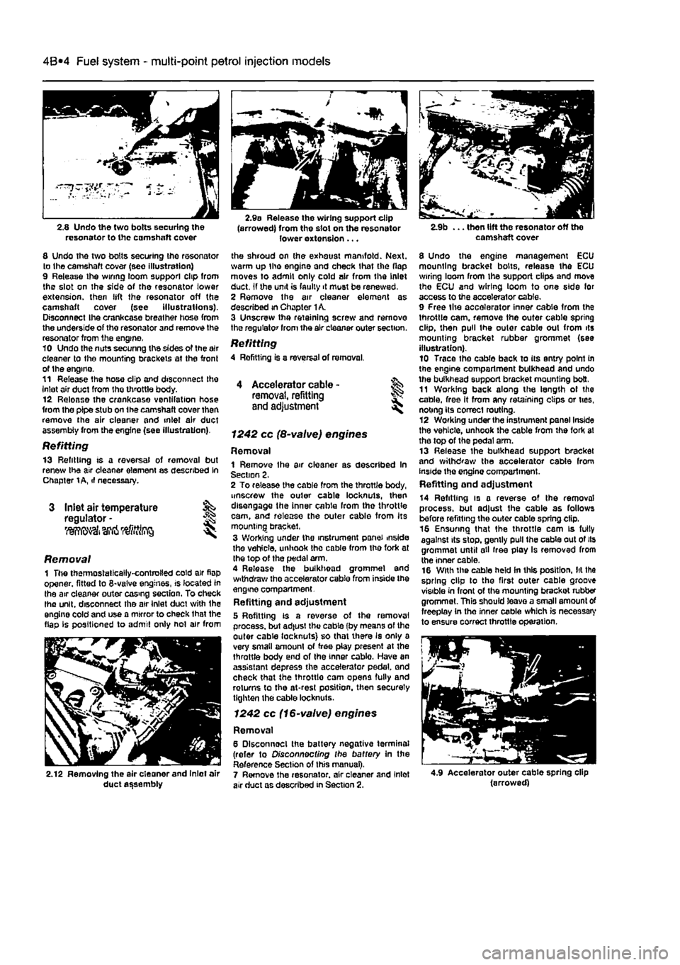
8 Undo the two bolts securing the resonator to the camshaft cover (see illustration) 9 Release ihe wiring loom support clip from the slot on the side of the resonator lower extension, then lift the resonator off the camshaft cover (see illustrations). Disconnect Ihe crankcase breather hose from the underside of tho resonator and remove the resonator from the engine. 10 Undo the nuts secunng the sides of the air cleaner to the mounting brackets at the front of the engino. 11 Release the hose clip and disconnect the inlet air duct from the throttle body. 12 Release the crankcase ventifation hose from the pipe stub on the camshaft cover then remove the air cleaner and inlet air duct assembly from the engine (see illustration).
Refitting 13 Refitting is a reversal of removal but renew the air cleaner element as described In Chapter
1 A,
if necessary.
Inlet air temperature regulator -liWfii' I
2.9o Release the wiring support clip (arrowed) from the slot on the resonator lower extension ...
the shroud on the exhaust manifold. Next, warm up tho engine and check that the flap moves to admit only cold air from the Inlet duct. If the unit is faulty it must be renewed. 2 Remove the air cleaner element as described in Chapter
1
A. 3 Unscrew tha retaining screw and remove tho regulator from the air cleaner outer section.
Refitting 4 Rofitting is a reversal of removal.
I
Removal 1 The thermostatically-controlled cold air flop opener, fitted to 8-valve engines, is located in the air cleaner outer cos>ng section. To check lha unit, disconnect the atr inlet duct with the engine cold and use a mirror to check that the flap Is positioned to admit only not air from
2.12 Removing the air cleaner and Inlet air duct assembly
4 Accelerator cable -removal, refitting and adjustment
1242 cc (8-valve) engines
Removal 1 Remove Ihe air cleaner as described In Section 2. 2 To release the cable from the throttle body, unscrew the outer cable locknuls, then disengage the inner cable from the throttle cam, and release the outer cable from its mounting bracket, 3 Wording under the instrument panel inside the vehicle, unhook the cable from tho fork at the top of the pedal arm. 4 Release the bulkhead grommel and withdraw tho accelerator cable from inside Ihe engine compartment. Refitting and adjustment 5 Refitting is a reverse of the removal process, but ad|ust the cable (by means of the outer cable locknuts} so that there Is only a very small amount of free play present at the throttle body end of the inner cablo. Have an assistant depress the accelerator pedal and check that the throttlo cam opens fully and returns to the at-rest position, then securely tighten the cable locknuts.
1242 cc (16-valve) engines
Removal 6 Dlsconnoel the battery negative terminal (refer to Disconnecting the battery in the Reference Section of this manual), 7 Remove the resonator, air cleaner and Inlet air duct as described in Section 2.
camshaft cover
8 Undo the engine management ECU mounting bracket bolts, release the ECU wiring loom from Ihe support clips and move tho ECU and wiring loom to one side for access to the accelerator cable. 9 Free the accelerator inner cable from the throttle cam, remove the outer cable spring clip, then pull the outer cable out from its mounting bracket rubber grommet (see illustration). 10 Trace the cable back to its entry point in the engine compartment bulkhead and undo the bulkhead support bracket mounting bolt. 11 Working back along the length of the cable, free It from any retaining clips or ties, noting its correct routing. 12 Working under the instrument panel Inside the vehicle, unhook the cable from the fork at the top of the pedal arm. 13 Release the bulkhead support bracket and withdraw the accelerator cable from inside the engino compartment. Refitting end adjustment
14 Refitting is a reverse of the removal process, but adjust the cable as follows before refitting the outer cable spring clip. 16 Ensuring that the throttle cam is fully against its stop, gently pull the cable out of its grommet until all free play Is removed from the inner cable. 16 With the cable held in this position, lit the spring clip to tho first outer cable groove visible in front of the mounting brackot rubber grommet. This should leave a small amount of freeplay in tho inner cable which is necessary to ensure correct throttle operation.
4.9 Accelerator outer cable spring clip (arrowed)
Page 131 of 225
4A*2 Fuel system -
single-point
petrol Injection models
17 Have an assistant depress the accelerator pedal and check that the throttle cam opens luily and returns smoothly to its stop. If necessary, reposition the spring clip In the next outer cable groove and recheck the throttle operation. 18 Refit the remainder of the disturbed components.
5 Engine management
system
^ components
(1242
cc, 8-vatve § engines) -
removal and refitting
^
Note: Refer to the warning given In Section T
before
proceeding.
Throttle body assembly
Removal 1 Remove the air cleaner and inlet air duct as described in Section 2. 2 Disconnect the wiring connectors from the throttle potentiometer, the idle control stepper motor and the inlet air temperature sensor. 3 Slacken the accelerator cable locknuts, then disengage the inner cable from the throttle cam and free the outer cable from its retaining bracket. Position the cable clear of the throttle body. 4 Unclip and disconnect the EVAP purge valve hose, and Ihe MAP sensor hose from the rear of the throttle body then, where applicable, disconnect the fuel pressure regulator vacuum hose from the front of the throttle body. 5 Slacken and remove the four bolts securing the throttle body assembly to the inlet manifold, then remove the assembly along with its insulating spacer. Refitting 6 Refitting is a reversal of the removal pro-cedure. bearing in mind the following points: 4! Examine the Insulating spacer for signs of damage, and renew If necessary. b) Ensure the throttle body, inlet manifold and insulating spacer mating surfaces are clean and dry, then fit the throttle body and spacer, and securely tighten the retaining bolts. c) Ensure ail hoses are correctly reconnected and, where necessary, /her their retaining clips are securely tightened. d) Adjust the accelerator cable as described in Section 4.
Fuel
rail and injectors
Removal 7 Disconnect the battery negative terminal (refer to Disconnecting tho battery in the Reference Section of this manual). 6 Remove the throttle body assembly as described earlier in this Section, however it is only necessary to move the unit to one side for access to the fuel rail and therefore it Is unnecessary to disconnect the accelerator caWe and hoses etc.
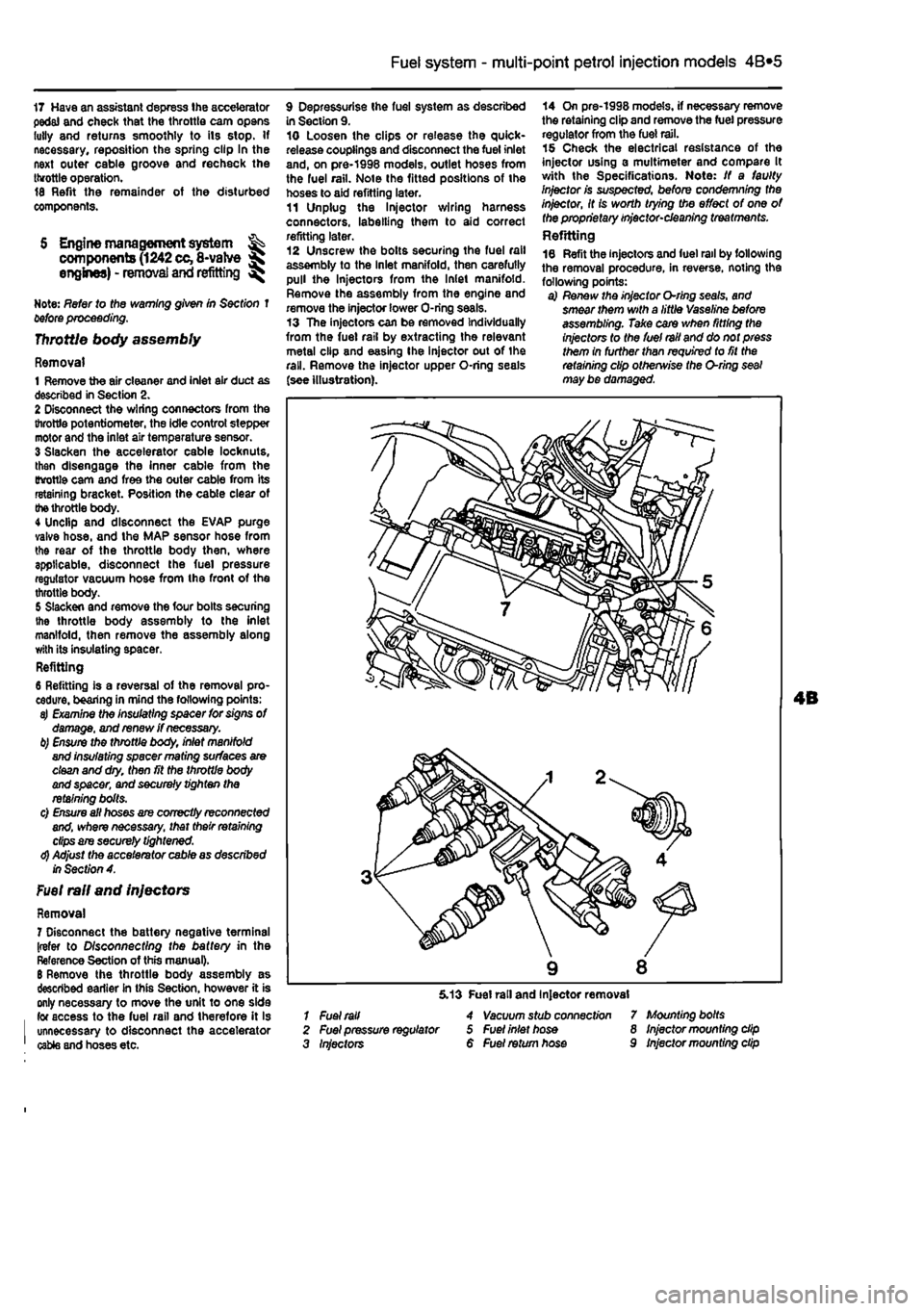
9 Depressurise Ihe fuel system as described in Section 9. 10 Loosen the clips or release the quick-release couplings and disconnect the fuel inlet and, on pre-1998 models, outlet hoses from the fuel rail. Note the fitted positions of the hoses to aid refitting later. 11 Unplug the ln}ector wiring harness connectors, labelling them to aid correct refitting later. 12 Unscrew the bolts securing the fuel rail assembly to the Inlet manifold, then carefully pull the Injectors from the Inlet manifold. Remove the assembly from the engine and remove the injector lower O-ring seals. 13 The injectors can be removed Individually from the fuel rail by extracting the relevant metal clip and easing Ihe injector out of the rail. Remove the injector upper O-ring seals (see illustration).
14 On pre-1998 models, if necessary remove the retaining clip and remove the fuel pressure regulator from the fuel rail. 15 Check the electrical resistance of the injector using a multimeter and compare It with the Specifications. Note: If a faulty Injector is suspected, before condemning the injector, It is worth trying the effect of one of the proprietary injector-cleaning treatments. Refitting 16 Refit the injectors and fuel rail by following the removal procedure, in reverse, noting the following points: a) Renew the injector O-rlng seals, and smear them with a little Vaseline before assembling. Take care when fitting the injectors to the fuel rail and do not press them in further than required to fit the retaining clip otherwise the O-ring seal may be damaged.
1 Fuel rail 2 Fuel pressure regulator 3 Injectors
5.13 Fuel rail and Injector removal 4 Vacuum stub connect/on 5 Fuel inlet hose 6 Fuel return hose
7 Mounting bolts 8 Injector mounting dip 9 Injector mounting dip
Page 132 of 225
4A*2 Fuel system -
single-point
petrol Injection models
b) Ensure that the injector retaining clips are securely seated c) Make sure the fuel supply and return hoses are correctly fitted as noted on removal, d) Check that all vacuum and electrical connections are remade
correcily
and securely. e) On completion check the fuel rail and injectors for fuel leaks.
Fuel pressure regulator Note: On J998 models onward, the fuel pressure regulator is an integral pad of the fuel pump and cannot be renewed separately. The following procedure applies to pre-1998 models only. Removal 17 Remove the air cleaner and inlet air ducts as described In Section 2. 18 Oepressurise the fuel system as described in Section 9. 19 Disconnect the vacuum hose from the port on the side of the regulator. 20 Extract the retaining clip and pull the pressure regulator out of Ihe fuel rail. 21 Remove the O-ring seal. Refitting 22 Refit the fuel pressure regulator by following Ihe removal procedure in reverse, noting the following points: a) Renew the O'ting seal and smear it with a little Vaseline before assembling. b) When fitting the retaining clip, use a suitable socket or metal tube (o press In the three anchorage points at Ihe same time. c) Refit the vacuum hose securely.
Idle control stepper motor
23 Refer to Chapter 4A.
Throttle potentiometer 24 Refer to Chapter 4A,
Intake air temperature sensor 25 Refer to Chapter 4A.
Manifold absolute pressure (MAP) sensor 26 Reler to Chapter 4A.
6.12a Disconnect the wiring connectors for the fuel injector harness ...
6.3 Disconnect the wiring connectors from the throttle potentiometer and the idle control stepper motor
Coolant temperature sensor 27 Refer to Chapter 4A. Crankshaft TDC sensor 28 Refer to Chapter 4A. Electronic control unit (ECU)
29 Refer to Chopter 4A.
Inertia safety switch 30 Refer to Chapter 4A. Fuel injection system relays 31 Refer to Chapter 4A.
6 Engine management system ^ components
(1242
cc,16-vatve S engines) - removal and refitting ^
Note: Refer to the warning given in Section t before proceeding.
Throttle body assembly
Removal 1 Remove the resonator, air cleaner and inlet air duct as described in Section 2. 2 Free Ihe accelerator inner cab
4 Slacken and remove the three bob j securing the throttle body assembly to ite inlet manifold. Ihen remove the assent?/ along with its insulating spacer. As the
throaii 1-
body is withdrawn, disconnect the vacuum hose from the underside of the unit. Refitting 5 Refitting is a reversal of the removal pi>: cedure, bearing in mind the following pants a) Examine the insulating spacer for signs d damage, and renew if necessary. b) Ensure the throttle body, inlet
manddd
and insulating spacer mating surfaces at -clean and dry. then fit the throttle
btxty
and spacer, and securely tighten the retaining bolts. c) Adjust Ute accelerator cable as desciter /nSecfw?4.
Fuel rail and injectors
Removal 6 Disconnect the battery negative termrul; (refer to Disconnecting the battery in ir*J Reference Section ol this manual), 7 Remove the resonator, air cleaner arid io«l 1 air duct as descnbed in Section 2. 8 Free the accelerator Inner cablc from l>*
1
throttle cam, remove the outer cable sprig. clip, then pull the outer cable out from
>H
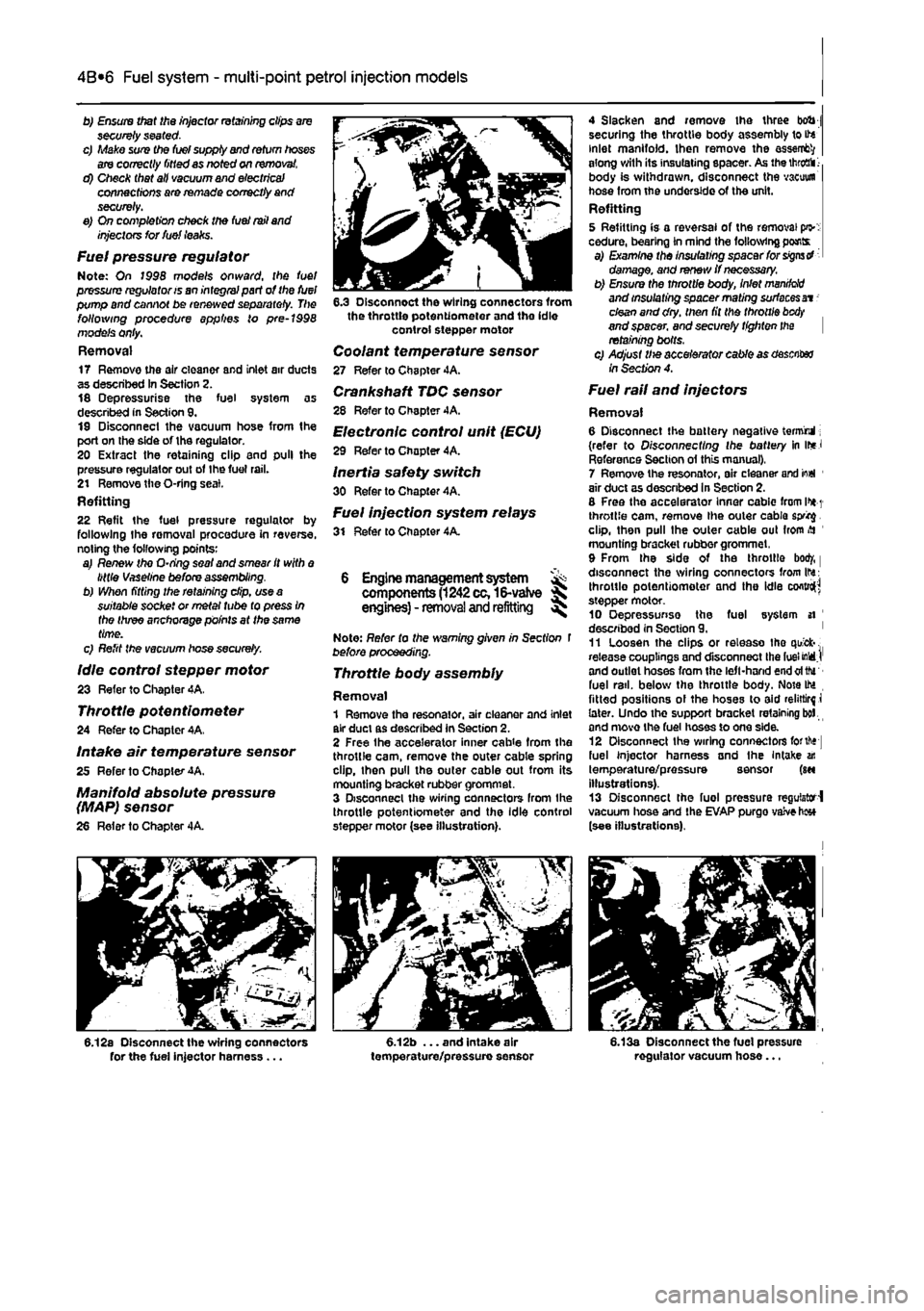
mounting bracket rubber grommet, 9 From the side of the throttle bod/, | disconnect the wiring connectors from Ihs: throttle potentiometer and the idle cofttro^ stepper motor. 10 Oepressunse the fuel system si ' described in Section 9. ' 11 Loosen the clips or release tho quick-. release couplings and disconnect the fuel MdJ' and outlet hoses from the left-hand end oftfu fuel rail, below the throttle body. Note IM fitted positions ol the hoses to aid relirtirf i later. Undo the support bracket retaining bol and move the fuel hoses to one side. 12 Disconnect Ihe wiring connectors forth* fuel injector harness and the Intake an temperature/pressure sensor (m illustrations). 13 Disconnect the fuel pressure regulator-! vacuum hose and the EVAP purgo vaive h«* (see illustrations).
6.13a Disconnect the fuel pressure regulator vacuum hose...
Page 133 of 225
4A*2 Fuel system -
single-point
petrol Injection models
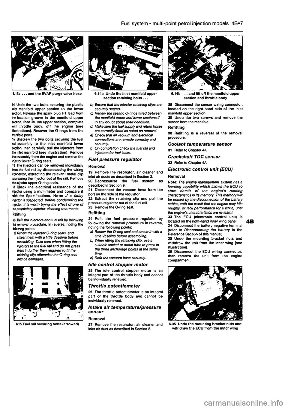
6.13b ... and tho EVAP purge valve hose
14 Undo the two bolls securing the plastic nlet manifold upper section to the lower section. Release the spark plug HT lead from Ihe location groove in the manifold upper section, then lift the upper section, complete with throttle body, off the engine (see illustrations). Recover the O-nngs from the manifold ports. 16 Unscrew the two bolts securing the fuel rail assembly to the Inlet manifold lower section, inen carefully pull the injectors from ttie inlet manifold (see Illustration). Remove
tt>e
assembly from the engine and remove the injector lower O-ring seals. t& The injectors can be removed individually from the fuel rail by disconnecting the wiring connector, extracting the relevant metal clip
ano
easing the injector out of the rail. Remove themjector upper O-ring seals. 17 Check the electrical resistance of the tractor using a multimeter and compare it with the Specifications. Note: If a faulty Rector fc suspected, before condemning Wie
Rector,
it is worth trying the effect of one of m
proprietary
injector-cleaning treatments. Refitting
15 Refit the injectors and fuel rail by following tie removal procedure, In reverse, noting the Mowing points:
4} Re/few
the Injector O-ring seals, and
smear
them with a little Vaseline before assembling. Take care when fitting the
injectors
to the fuel rail and do not press
them
in further than required to fit the
retaining
clip otherwise the O-ring
seal may
be damaged.
6.14a Undo the inlet manifold upper section retaining bolts ... b) Ensure that the injector retaining clips are securely seated. c) Renew the sealing O-nngs fitted between the manifold upper and lower sections if in any doubt about their condition. d) Make sure the fuel supply and return hoses are correctly fitted as noted on removal. e) Check that all vacuum and electrical connections are remade correctly and securely. f) On completion check the fuel rail and injectors tor fuel leaks.
Fuel pressure regulator
Removal 19 Remove the resonator, air cleaner and inlet air ducts as described In Section 2. 20 Depressurise the fuel system as described In Section 9. 21 Disconnect the vacuum hose from the port on the side of the regulator. 22 Extract the retaining clip and pull the pressure regulator out of the fuel rail. 23 Remove the O-ring seal. Refitting 24 Refit the fuel pressure regulator by following the removal procedure in reverse, noting the following points: a) Renew the O-ring
seaJ
and smear it with a little Vaseline before assembling. b) When fitting the retaining clip, use a suitable socket or metal tube to press in the three anchorage points at the same time. c) Refit the vacuum hose securely.
Idle control stepper motor 25 The idle control stepper motor is an Integral part of the throttle body and cannot be individually renewed.
Throttle potentiometer 26 The throttle potentiometer Is an integral part of the throttle body and cannot be individually renewed.
Intake air temperature/pressure sensor
Removal
6.14b ... and lift off the manifold upper section and throttle body 28 Disconnect the sensor wiring connector, located on the right-hand side of the Inlet manifold upper section. 29 Undo the two screws and remove the sensor from the manifold. Refitting 30 Refitting is a reversal of the removal procedure. Coolant temperature sensor 31 Refer to Chapter 4A.
Crankshaft TDC sensor 32 Refer to Chapter 4A.
Electronic control unit (ECU)
Removal Note: 77?e engine management system has a learning capability which allows the ECU to store details of the engine's running characteristics in Its memory. This memory will be erased by the disconnection of the battery cables, with the result that the engine may idle roughly, or lack performance for a while, until the engine's characteristics are re-learnt. 33 The ECU (electronic control unit) is located on the right-hand inner wing panel. 34 Disconnect the battery negative terminal (refer to Disconnecting the battery In the Reference Section of this manual). 35 Undo the mounting bracket nuts and withdraw the unit from the inner wing (see Illustration). 36 Disconnect the ECU wiring connector, then remove the unit from the engine compartment.
6.15 Fuel rail securing bolts (arrowed) 27 Remove the resonator, air cleaner and inlet air duct as described in Section 2. 6.35 Undo the mounting bracket nuts and withdraw the ECU from the inner wing
Page 134 of 225
4A*2 Fuel system -
single-point
petrol Injection models
Refitting 37 Refitting Is a reversal of removal making sure that the wiring connector is securely reconnected.
Inertia safety switch 36 Refer to Chapter 4A, Fuel injection system relays Removal 39 The fuel injection system twin relay Is located under a plastic cover on the engine compartment bulkhead. 40 The main purpose of the relay Is to supply current to the fuel pump, ignition coils, oxygen sensor, Injectors and EVAP solenoid. The relay is controlled by the ignition switch. A15 amp fuse, protecting ihe fuel pump, oxygen sensor and EVAP solenoid is located adjacent to the relay. 41 Remove the cover and pull the relay directfy from Its socket. Refitting 42 Refitting is a reversal of removal.
7 Fuel pump and fuel gauge sender unit - JK removal
and
refitting ^
Removal Note: Refer fo (he warning given in Section 1 before proceeding. 1 Disconnect the battery negative terminal (refer to Disconnecting the battery In the Reference Section of this manual). 2 Depreasurise the fuel system as described in Section 9. 3 Remove the rear soat as described In Chapter 11. Prise the fuel pump access cover out of the floor panel to gain access to the pump unit. On later models, undo the three retaining screws to release the cover. 4 Disconnect the wiring connector. 5 Bearing In mind the warning given In Section t, disconnect Ihe fuel supply and, where applicable, the return lines from tho pump unit by pressing the tabs. Plug the ends of the lines or cover them with adhesive tape. 6 Using a suitable tool, unscrew the large ring nut and carefully withdraw the fuel pump/fuel tank sender unit assembly from the fuel tank, along with its sealing rtng. 7 If necessary, the unit can be dismantled and the pump and sender unit separated. If this is (he case, carefully note the correct fitted positions of all components while dismantling the unit, and use these notes on reassembly to ensure that all items are correctly fitted.
Refitting 8 Refitting is a reversal of the removal procedure using a new sealing ring. Prior to refitting the access cover, reconnect the battery, then start the engine and check the fuel line unlon(s) (or signs of i
Fuel
tank -removal and refitting
Refer to Chapter 4A.
9 Fuel injection system -depressurisatton
Note: Refer to the warning given In Section 1 before proceeding.
A
Warning: The following procedure will merely relieve the pressure In the fuel system • remember that fuel will still be present In the system components and take precautions accord-ingly before disconnecting any of them. 1 The fuel system referred to in this Section is defined as the lank-mounted fuel pump, tha fuel filter, the fuel rail, the fuel injectors, and the metal pipes and flexible hoses of the fuel lines between these components. All these contain fuel which will be under pressure while the engine Is running and/or while the Ignition is switched on. The pressure will remain for some time after the Ignition has been switched off. and must be relieved before any of these components are disturbed for servicing work. 2 Disconnect the battery negative terminal (refer to Disconnecting the battery In the Reference Section of this manual). 3 Have a large rag ready to cover the union to be disconnected and, if possible, place a con-tainer beneath the relevant connection/union. 4 Slowly loosen the connection or union nut (as applicable) to avoid a sudden release of pressure, and ensure that the rag is wrapped around the connection to catch any fuef spray which may be expelled. Once the pressure is released, disconnect the fuel line, and Insert plugs to minimise fuel loss and prevent the entry of dirt Into the fuel system. Note that on later models, quick-release fuel couplings are used on many of the fuel line connections. To release these couplings, depress the two clips on the side of the coupling while keeping the fuel line pushed In. With the clips depressed, slowly withdraw the fuel line from the coupling allowing the fuel pressure to release, then withdraw the fuel line fully.
10 Inlet manifold-removal
and
refitting
Note: Refer fo the warning given in Section 1 before proceeding.
1242 cc (8-valve) engines
Removal 1 Remove ihe throttle body assembly as described in Section 5.
2 Remove the fuel rail and injectors at described in Section 5. 3 Drain the cooling system ss described n Chapter 1A. 4 Disconnect the wiring connector from ih* coolant temperature sensor (situated on it* left-hand side of the manifold). 5 Undo the bolt securing the accelerator cable mounting bracket to the manifold, am position it clear of the manifold. 6 Slacken the retaining clip and disconnect the coolant hose from the rear of the mandold 7 Disconnect the brake vacuum hose, 6 Undo the seven manifold retaining nuisw bolts, and remove the manifold from tta engine. Remove the gasket and discard tti new one should be used on refitting. Refitting
9 Refitting is a reverse of the removjf procedure, noting the following points: a) Ensure that the manifold and cylinder lim mating surfaces are dean and
dry.
and fill new manifold gasket. Refit the
manifold
and securely tighten Its retaining
nuts.
b) Ensure all relevant hoses are recorwscfed fo their original positions and are
sacurtfy
held (Where necessary; by the
retaining
clips. c) Refit the fuel rail and injectors, and
the
throttle body assembly with
reference to
Sect/on 5. d) On completion, refill the cooling
system
as described in Chapter 1A. 1242 cc (16-valve) engines
Removal 10 Disconnect the battery negative ternnncf (refer to Disconnecting the battery in ths Reference Section of this manual). 11 Remove the resonator, air cleaner and inlet air duct as described In Section 2. 12 Drain the cooling system as described r, Chapter 1A. 13 Free the accelerator inner cable from IN throttle cam. remove the outer cable spring dip. then pull the outer cable out from itt mounting bracket rubber grommet. 14 From the side of the throttle boOf, disconnect the wiring connectors from the throttle potentiometer and the Idle contrd stepper motor. Disconnect the coolant temperature sensor wiring connector located in the Inlet manilold below the throttie bodr, and disconnect the brake servo vacuum hose. 15 Disconnect Ihe wiring connectors for the fuel in|ector harness and the Intake a* temperature/pressure sensor, thtn disconnect the fuel pressure regulator vacuum hose and the EVAP purge valve
hose
(see illustration). 16 Undo Ihe two bolts securing the plastic Inlet manifold upper section to the lower section. Release the spark plug HT lead from the location groove in the manifold upper section, then lift Ihe upper section, complete with throttle body, off the engine. Recover
the
O-rings from the manifold pons.
Page 139 of 225
Fuel system - diesel models 4C*3
bolt (Bosch)
4 Fuel system -priming and bleeding
The Injection pump Is self-priming and no special procedures are necessary to prime the fuel system. However where the luei system has been completely drained it (s helpful to loosen the injector union nuts while turning the engine on the starter motor In order to purge trooped air.
S Fuel injection pump • removal and refitting 5
Removal 1 Disconnect the battery negative terminal (refer to Disconnecting the battery In the Reference Section of this manual) 2 Remove the timing belt and Injection pump sprocket aa described in Chapter 2C. 3 Disconnect the accelerator cable from the fuel injection pump, with reference to Section 3. 4 Loosen the clip, or undo the banjo union, and disconnect the fuel supply hose. Recover the sealing washers from the banjo union, where applicable. Cover the open end of the hose, and raflt and cover the banjo bolt to keep dirt out. 5 Disconnect the main fuel return pipe and the injector leak-off return pipe banjo union. Recover the sealing washers from the banjo union Again, cover the open end of the hose and the banjo bolt to keep dirt out.
6.2a Remove the rubber bung ...
k
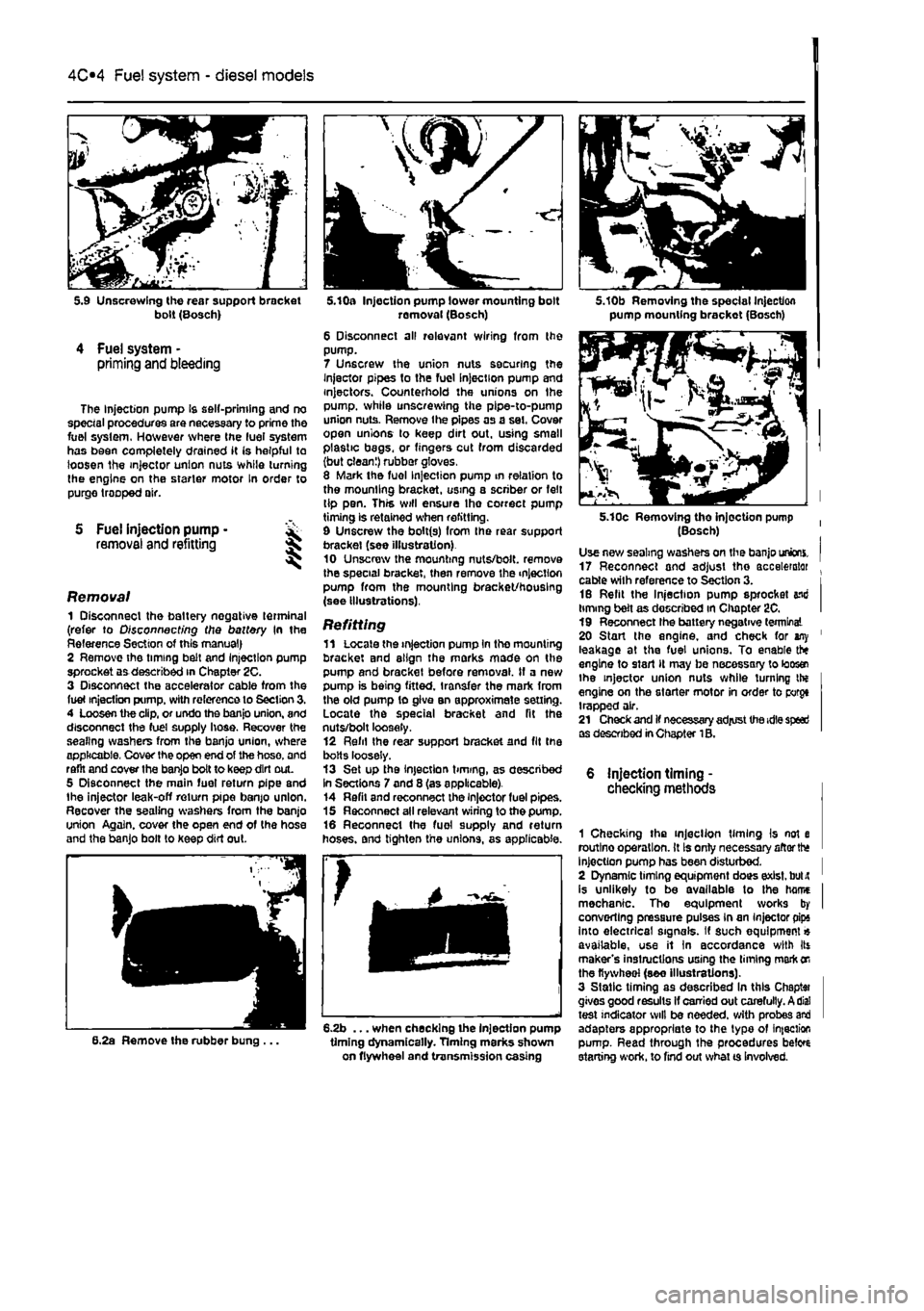
5.10a Injection pump lower mounting bolt removal (Bosch) 6 Disconnect all relevant wiring from the pump. 7 Unscrew the union nuts securing the Injector pipes to the fuel Injection pump and injectors. Counterhold the unions on Ihe pump, while unscrewing the pipe-to-pump union nuts. Remove the pipes as a set. Cover open unions lo keep dirt out. using small plastic begs, or fingers cut from discarded (but clean!) rubber gloves. 8 Mark the fuel Injection pump in relation to the mounting bracket, using a scriber or felt tip pen. This will ensure Ihe correct pump timing is retained when refitting. 9 Unscrew the bolt(s) from Ihe rear support bracket (see illustration) 10 Unscrew the mounting nuts/bolt, remove the special bracket, then remove the injection pump from the mounting bracket/housing (see illustrations).
Refitting 11 Locate the injection pump In the mounting bracket and align the marks mode on the pump and bracket before removal. If a new pump is being fitted, transfer the mark from the old pump to give an approximate setting. Locate the special bracket and fit the nuts/bolt loosely. 12 Refil Ihe rear support bracket and fit the bolts loosely. 13 Set up the injection timing, as described In Sections 7 and 8 (as applicable). 14 Refil and reconnect the injector fuel pipes. 15 Reconnect all relevant wiring to the pump. 16 Reconnect the fuel supply and return hoses, and tighten the unions, as applicable.
6.2b ... when checking the injection pump timing dynamically. Timing marks shown on flywheel and transmission casing
5.10b Removing the special Injection pump mounting brackot (Bosch)
5.10c Removing tho injection pump (Bosch) Use new sealing washers on the banjo unions. 17 Reconnect and adjust the accelerator . cable with reference to Section 3. i 16 Refit the Injection pump sprocket end timing belt as described in Chapter 2C. I 19 Reconnect Ihe battery negative terminal 20 Start the engine, and check for any ' leakage at the fuel unions. To enable the engine to start It may be necessary to loos® the injector union nuts while turning the engine on the starter motor in order to porgt trapped air. 21 Check and if necessary adjust the idle speed as described in Chapter 1B.
6 injection timing -checking methods
1 Checking the injection timing Is not e routlno operation. It Is only necessary aftorth* Injection pump has been disturbed. I 2 Dynamic timing equipment does exist, bulit ' is unlikely to be available to the hame I mechanic. Tho equipment works by I converting pressure pulses in an Injector pips into electrical signals. If such equipment« available, use it In accordance with Its maker's instructions using the liming mark
on
the flywheel (see illustrations). 3 Static timing as described In this Chaptai gives good results If carried out carefully. A dial test indicator will be needed, with probes and adapters appropriate to the typo of infection pump. Read through the procedures beto starting work, to find out what ts Involved.
Page 140 of 225
Fuel system - diesel models
4C*3
7.4 Unscrew the access screw from the 7.5 Dial gauge and adapter (Bosch) rear of the Injection pump (Bosch)
7 Injection timing ^ (Bosch fuel injection pump) -checking and adjustment ^
Caution: Some of the Injection pump uttlngs and access plugs may be sealed ty the manufacturers at the factory, using
paint
or locking wire and lead seals. Do not
disturb
the seals If the vehicle is still within the warranty period, otherwise the warranty will be invalidated. Also do not attempt the timing procedure unless
accurate
Instrumentation Is available. Note: To check the injection pump timing a special
timing
probe and mounting bracket is required. Without access to this piece of
tquipment.
injection pump timing should be intrusted to a Fiat dealer or other suitably
eqwpped
specialist. 1
H
the Injection timing is being checked with ffie pump in position on the engine, rather rian as part ot the pump refitting procedure, disconnect the battery negative terminal (refer to
Disconnecting
the battery in the Reference S«ction of this manual), and remove the air rtel ducting from the front of the engine. 2 Unscrew the union nuts and disconnect the injector pipes from the Injection pump and injectors. Counterhold the unions on the pump, while unscrewing the pipe-to-pump irion
nuts.
Remove the pipes as a set. Cover open unions to keep dirt out, using small plastic bags, or fingers cut from discarded
ibut clean!)
rubber gloves. 3 Referring to Chapter 2C, set the engine at
TDC on
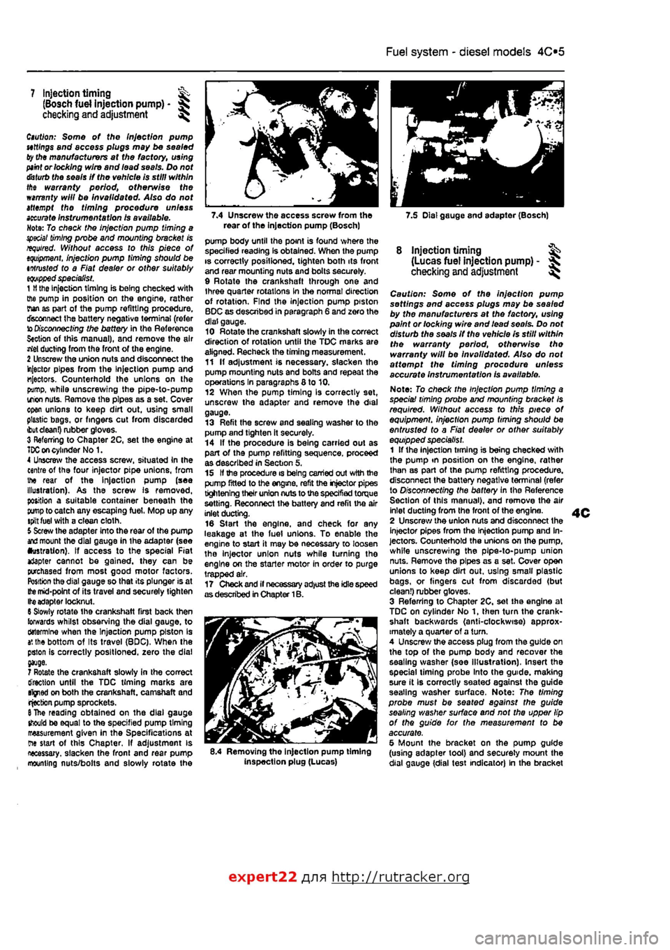
cylinder No 1. 4 Unscrew the access screw, situated In the centre of the four injector pipe unions, from the rear of the Injection pump (see illustration). As the screw Is removed, position a suitable container beneath the
pump
to catch any escaping fuel, Mop up any tpilt fuel with a clean cloth. 5 Screw the adapter into the rear of the pump
and
mount the dial gauge in ihe adapter (see •ustration). If access to the special Fiat *Japter cannot be gained, they can be purchased from most good motor factors. Position the dial gauge so that its plunger is at
Ifce
mid-point of its travel and securely tighten Ite adapter locknut. 6 Slowly rotate the crankshaft first back then towards whilst observing the dial gauge, to ctotermlne when the Injection pump piston is
a',
the bottom of Its travel (BDC), When the pston Is correctly positioned, zero the dial
7 Rotate the crankshaft slowly in the correct direction until the TDC timing marks are tfjned on both the crankshaft, camshaft and rjecbon pump sprockets.
6
The reading obtained on the dial gauge should be equal to the specified pump timing measurement given in the Specifications at ew start of this Chapter, If adjustment is necessary, slacken the fronl and rear pump mounting nuts/bolts and slowly rotate the
pump body until the point is found where the specified reading Is obtained. When the pump is correctly posilioned, tighten both its front and rear mounting nuts and bolts securely. 9 Rotate the crankshaft through one and three quarter rotations in the normal direction of rotation. Find the injection pump piston BDC as described in paragraph 6 and zero the dial gauge. 10 Rotate the crankshaft slowly in the correct direction of rotation until the TDC marks are aligned. Recheck the timing measurement. 11 If adjustment is necessary, slacken the pump mounting nuts and bolts and repeat the operations In paragraphs 8 to 10. 12 When the pump timing Is correctly set, unscrew the adapter and remove the dial gauge. 13 Refit the screw and sealing washer to the pump and tighten it securely. 14 If the procedure is being carried out as part of the pump refitting sequence, proceed as described in Section 5, 15 If the procedure is being carried out with the pump fitted to the engine, refit the injector pipes tightening their union nuts to the specified torque setting. Reconnect the battery and refit the air inlet ducting. 16 Start the engine, and check for any leakage at the luel unions. To enable the engine to start it may be necessary to loosen the injector union nuts while turning tho engine on the starter motor in order to purge trapped air. 17 Check and if necessary adjust the idle speed as described in Chapter 1B.
8.4 Removing the injection pump timing inspection plug (Lucas)
8 injection timing ^ (Lucas fuel injection pump) - ^ checking
and
adjustment ^
Caution: Some of the injection pump settings and access plugs may be sealed by the manufacturers at the factory, using paint or locking wire and lead seo/s. Do not disturb the seals if the vehicle Is still within the warranty period, otherwise tho warranty will be Invalidated. Also do not affempf the timing procedure unless accurate instrumentation is available.
Note: To check the Injection pump timing a speciai timing probe and mounting bracket Is required. Without access to this piece of equipment, injection pump timing should be entrusted to a Fiat dealer or other suitably equipped specialist. 1 If the injection timing is being checked with the pump tn position on the engine, rather than as part of the pump refitting procedure, disconnect the battery negative terminal (refer to Disconnecting the battery in the Reference Section of this manual), and remove the air inlet ducting from the front of the engine. 2 Unscrew the union nuts and disconnect the injector pipes from the Injection pump and In-jectors. Counterhold the unions on the pump, while unscrewing the pipe-to-pump union nuts. Remove the pipes as a set. Cover open unions to keep dirt out. using smalt plastic bags, or fingers cut from discarded (but clean!) rubber gloves. 3 Referring to Chapter 2C, set the engine at TDC on cylinder No 1, then turn the crank-shaft backwards (anti-clockwise) approx-imately a quarter of a turn. 4 Unscrew the access plug from the guide on the top of the pump body and recover the sealing washer (soe Illustration). Insert the special liming probe Into the guide, making sure it Ib correctly seated against the guide seating washer surface. Note: The timing probe must be seated against the guide sealing washer surface and not the upper lip of the guide for the measurement to be accurate. 5 Mount the bracket on the pump guide (using adapter tool) and securely mount the dial gauge {dial test indicator) In the bracket
expert22 fl/i* http://rutracker.org
Page 144 of 225
4D«1
Chapter 4 Part D:
Exhaust and emission control systems
Contents
Catalytic converter - general Information and precautions 7 Crankcase emission system • general information 3 Evaporative loss emission control system • information and component renewal 2
Degrees of difficulty
Exhaust manifold - removal and refitting 5 Exhaust system - general information and component renewal .... 6 General information 1 Lambda oxygen sensor - removal and refitting 4
Easy, suitable
tor novice with fittie ^
1 experience
Fairly easy, suitable for beginner with ^ some experience ^
Fairiy dfficult, lb suitable for competent ^ DIY mechanic ^
Difficult, suitable for experienced DIY ^ mechanic
Very difficult, ^ suitable far expert DIY or professional
Specifications
Torque wrench settings Exhaust down pipe to manifold Exhaust manifold Exhaust system mounting Exhaust to catalytic converter: M8 M10x1.25
Nm Ibfft 24 18 24 18 27 20
24 18 40 30 53 39
1 General information
Emission control systems All petrol engine models use unleaded petrol and are controlled by engine management systems that are 'tuned' to give the best compromise between driveability. luel consumption and exhaust emission production. In addition, a number of systems are fitted that help to minimise other harmful emissions: a crankcase emission-control system (petrol models only) that reduces the release of pollutants from the crankcase, an evaporative loss emission control system (petrol models only) to reduce the release of hydrocarbons from the fuel tank, a catalytic converter (petrol and diesel models) to reduce exhaust gas pollutants, and an Exhaust Gas Recirculation (EGR) system (turbo diesel models only) to reduce exhaust emissions. Crankcase emission control To reduce the emission of unburned hydrocarbons from the crankcase Into the atmosphere, the engine is sealed and the blow-by gases and oil vapour are drawn from inside the crankcase, through a flame trap.
into the inlet tract to be burned by the engine during normal combustion. Under conditions of high manifold depression (idling, deceleration) the gases will by sucked positively out of the crankcase. Under conditions of low manifold depression (acceleration, full-throttle running) ihe gases are forced out of the crankcase by the (relatively) higher crankcase pressure: if the engine is worn, the raised crankcase pressure (due to increased blow-by) will cause some of the flow to return under all manifold conditions. Exhaust emission control -petrol models To minimise the amount of pollutants which escape Into the atmosphere, a catalytic converter is fitted In the exhaust system. The fuel system is of the closed-loop type, in which a Lambda (or oxygen) sensor In the exhaust system provides the engine management system ECU with constant feedback, enabling the ECU to adjust the air/fuel mixture to optimise combustion. The Lambda sensor has a heating element built-in that Is controlled by the ECU through the Lambda sensor relay to quickly bring the sensor's tip to Its optimum operating temperature. The sensor's tip Is sensitive to oxygen and relays a voltage signal to the ECU
that varies according on the amount of oxygen In the exhaust gas. If the inlet air/fuel mixture is too rich, the exhaust gases are low in oxygen so the sensor sends a low-voltage signal, the voltage rising as the mixture weakens and the amount of oxygen rises In the exhaust gases. Peak conversion efficiency of all major pollutants occurs if the inlet air/fuel mixture Is maintained at the chemlcally-con*ect ratio for the complete combustion of petrol of 14.7 parts (by weight) of air to
1
part of fuel (the stoichiometric ratio). The sensor output voltage alters in a large step at this point, the ECU using the signal change as a reference point and correcting the Inlet air/fuel mixture accordingly by altering the fuel Injector pulse width. Exhaust emission control -diesel models An oxidation catalyst is fitted in the exhaust system of all diesel engine models. This has the effect of removing a large proportion of the gaseous hydrocarbons, carbon monoxide and particulates present in the exhaust gas. An Exhaust Gas Recirculation (EGR) system Is fitted to all turbo diesel engine models. This reduces the level of nitrogen oxides produced during combustion by Introducing a proportion of the exhaust gas back into the inlet manifold, under certain engine operating
Page 146 of 225
4D*3 Exhaust and emission control systems
Refitting 8 Refitting is a reversal of the removal pro-cedure but fit new gaskets. Tighten the nuts lo the specified torque.
Diesel models Note: On diesel models the inlet and exhaust
manifolds
are located on the rear of the engine
end
share the same securing nuts and gasket. Removal 8 Remove the inlet manifold as described In Part
C
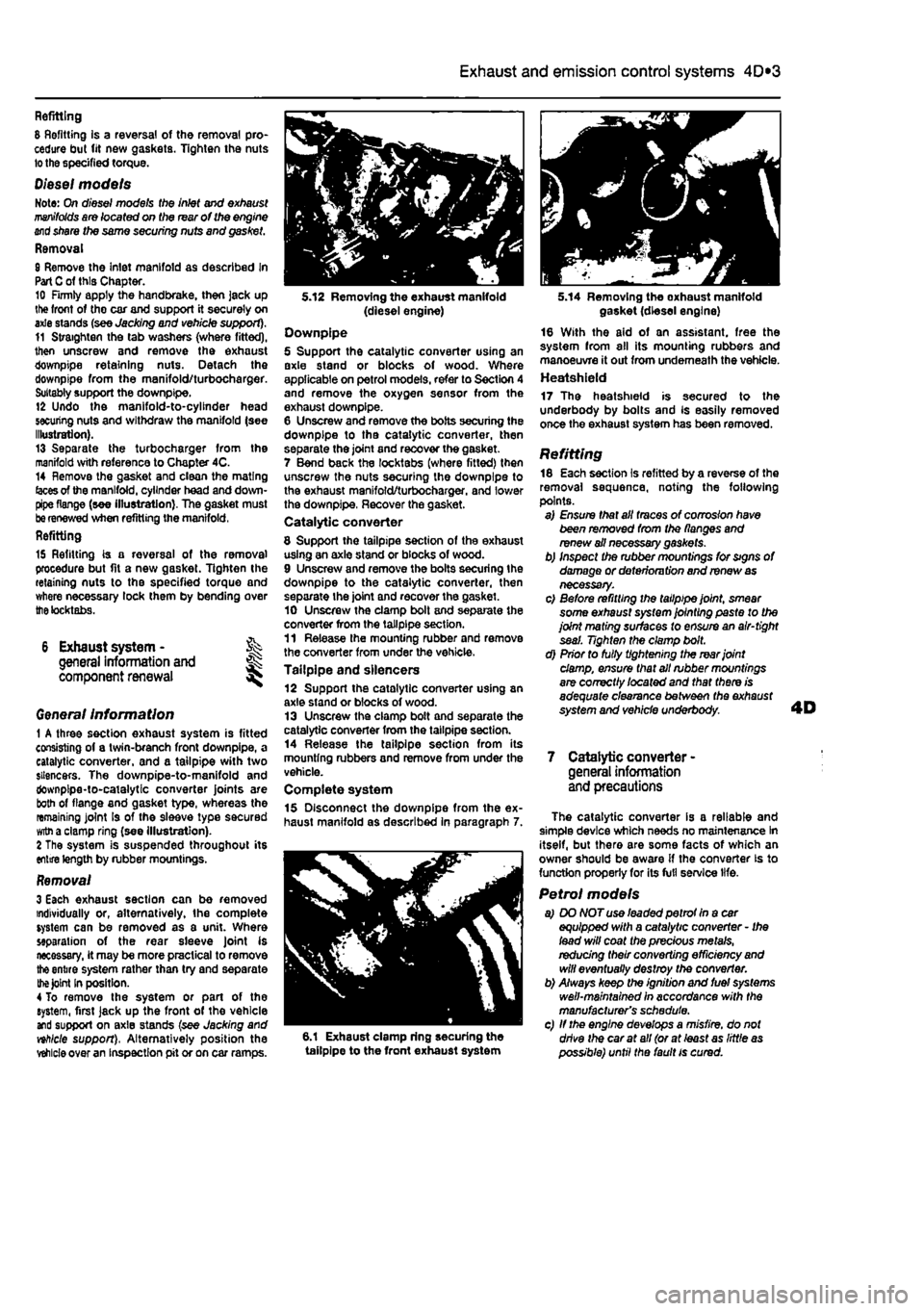
of this Chapter. 10 Firmly apply the handbrake, then jack up lite front of tho car and support it securely on axle stands (see Jacking and vehicle support). 11 Straighten the tab washers (where fitted), then unscrew and remove the exhaust downpipe retaining nuts. Detach the downpipe from the manifold/turbocharger. Suitably support the downpipe. 12 Undo the manifold-to-cylinder head securing nuts and withdraw the manifold (see Illustration). 13 Separate the turbocharger from the manifold with reference to Chapter 4C. 14 Remove the gasket and clean the mating
(aces
of the manifold, cylinder head and down-pipe flange (see illustration). The gasket must
be
renewed when refitting the manifold, Refitting
15 Refitting is a reversal of the removal procedure but fit a new gasket. Tighten the retaining nuts to the specified torque and where necessary lock them by bending over
the
tocktabs.
6 Exhaust system - % general information and ^ component renewal
Genera/ Information 1 A three section exhaust system is fitted consisting of a twin-branch front downpipe, a catalytic converter, and a tailpipe with two silencers. The downpipe-to-manifold and downpipe-to-catalytic converter joints are both of flange and gasket type, whereas the remaining joint Is of the sleeve type secured
witn
a clamp ring (see illustration). 2 The system is suspended throughout its entire length by rubber mountings.
Removal 3 Each exhaust section can be removed individually or, alternatively, the complete system can be removed as a unit. Where separation of the rear sleeve Joint is necessary, it may be more practical to remove
the
entire system rather than try and separate
the Joint
In position. 4 To remove the system or part of the system, first jack up the front of the vehicle and support on axle stands (see Jacking and nhlcle support), Alternatively position the
vehicle
over an inspection pit or on car ramps.
5.12 Removing the exhaust manifold (diesel engine) Downpipe 5 Support the catalytic converter using an axle stand or blocks of wood. Where applicable on petrol models, refer to Section 4 and remove the oxygen sensor from the exhaust downpipe. 6 Unscrew and remove the bolts securing the downpipe to tha catalytic converter, then separate the joint and recover the gasket. 7 Bend back the locktabs (where fitted) then unscrew the nuts securing the downpipe to the exhaust manifold/turbocharger. and lower the downpipe, Recover the gasket. Catalytic converter
8 Support the tailpipe section of the exhaust using an axle stand or blocks of wood. 9 Unscrew and remove the bolts securing the downpipe to the catalytic converter, then separate the joint and recover the gasket. 10 Unscrew the clamp bolt and separate the converter from the tailpipe section. 11 Release the mounting rubber and remove the converter from under the vehicle. Tailpipe and silencers 12 Support the catalytic converter using an axle stand or blocks of wood. 13 Unscrew the clamp bolt and separate the catalytic converter from the tailpipe section. 14 Release the tailpipe section from its mounting rubbers and remove from under the vehicle. Complete system 15 Disconnect the downpipe from the ex-haust manifold as described in paragraph 7.
6.1 Exhaust clamp ring securing the tailpipe to the front exhaust system
5.14 Removing the oxhaust manifold gasket (diesel engine) 16 With the aid of an assistant, free the system from all its mounting rubbers and manoeuvre it out from underneath the vehicle. Heatshield 17 The heatshield is secured to the underbody by bolts and Is easily removed once the exhaust system has been removed.
Refitting 18 Each section is refitted by a reverse of the removal sequence, noting the following points. a) Ensure that all traces of corrosion have been removed from the flanges and renew ail necessary gaskets. b) Inspect the rubber mountings for signs of damage or deterioru tion and renew
as
necessary. c) Before refitting the tailpipe joint, smear some exhaust system jointing paste to the joint mating surfaces to ensure an air-tight seal. Tighten the clamp bolt. d) Prior to fully tightening the rear joint damp, ensure that all rubber mountings are correctly /ocafed and that there is adequate clearance between the exhaust system and vehicle underbody.
7 Catalytic converter -general information and precautions
The catalytic converter is a reliable and simple device which needs no maintenance In itself, but there are some facts of which an owner should be aware if the converter is to function properly for its full service life.
Petrol models a) DO NOT use leaded petrot In a car equipped with a catalytic converter - Ihe lead will coat the precious metals, redudng their converting efficiency
and
will eventually destroy the converter. b) Always keep the ignition and fuel systems well-maintained in accordance with the manufacturer's schedule. c) If the engine develops a misfire, do not drive the car at all (or at least as little
as
possible) until the fault is cured.