bearing FIAT PUNTO 1998 176 / 1.G Service Manual
[x] Cancel search | Manufacturer: FIAT, Model Year: 1998, Model line: PUNTO, Model: FIAT PUNTO 1998 176 / 1.GPages: 225, PDF Size: 18.54 MB
Page 160 of 225
Clutch 6*3
6 WorWng inside the vehicle, extract the split pin and remove the washer securing the master cylinder pushrod to the clutch pedal. Dsoonnect the pushrod from the pivot. 7 Have an assistant support the master cylinder In the engine compartment, then unscrew the mounting bolts. Withdraw the master cylinder from the engine compartment, 8 II is not possible to obtain an overhaul kit from Flat however some motor factors may be abls to supply one. Follow the Instructions with the repair kit if obtained.
Refitting 9 Refit the clutch master cylinder by following ihe removal procedure In reverse, noting the following. a) Apply a
Utile
high-melting point grease to the clutch pedal pivot. b) Tighten the mounting bolts and union nut securely. cj Fit a new split pin to the pushrod. d) Where removed, refit the alternator
as
described In Chapter 5A e) On completion bleed the clutch hydraulic system as descnbed in Section
A.
7 Clutch assembly -
removal,
inspection
and
refitting
S Clutch slave cylinder-removal and refitting
Note: This procedure applies to models fitted
ivrth
the hydraulically-operated clutch release mechanism. Note: Refer to the warning at the beginning
of
Section A regarding the hazards of working
with
hydraulic fluid.
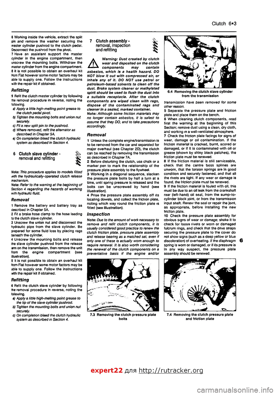
Removal 1 Remove the battery and battery tray as described in Chapter 5A. 2 Fit a brake hose clamp to tha hose leading to the clutch slave cylinder. 3 Unscrew the union nut and disconnect the hydraulic pipe from the slave cylinder. Be prepared for some fluid loss by placing rags beneath the cylinder. 4 Unscrew the mounting bolts and release the slave cylinder pushrod from the release am on the transmission, then remove the unit from the engine compartment (see Illustration). 5 It is not possible to obtain an overhaul kit from Flat however some motor factors may be able to supply one. Follow tha instructions with the repair kit if obtained.
Refitting 6 Refit the clutch slave cylinder by following the removal procedure In reverse, noting the following. a) Apply a little high-melting point grease to the tip of the slave cylinder pushrod. b) Tighten the mounting bolts and union nut securely. c) On completion bleed the dutch hydraulic system as described in Section A.
A
Warning: Dust created by clutch wear and deposited on the clutch components may contain asbestos, which Is a health hazard. DO NOT blow it out with compressed air, or inhale any of it. DO NOT use petrol or petroleum-based solvents to clean off the dust. Brake system cleaner or methylated spirit should be used to flush the dust Into a suitable receptacle. After the clutch components are wiped clean with rags, dispose of the confam/nafed rags and cleaner In a sealed, marked container. Note: Although some friction materials may no longer contain asbestos, it is safest to assume that they DO. and to take precautions accordingly.
Removal 1 Unless the complete engine/transmission is to be removed from the car and separated for major overhaul (see Chapter 2D), Ihe clutch can be reached by removing the transmission as descnbed in Chapter 7A, 2 Before disturbing the clutch, use chalk or a marker pen to mark the relationship of the pressure plate assembly to the flywheel. 3 Working In a diagonal sequence, slacken the pressure plate bolts by half a turn at a time, until spring pressure Is released and the bolls can be unscrewed by hand (see Illustration). 4 Prise the pressure piate assembly off its locating dowels, and collect the friction plate, noting which way round the friction plate is fitted (see Illustration).
Inspection Note: Due to the amount of work necessary to remove and refit clutch components, It is usually considered good practice to renew the clutch friction plate, pressure plate assembly and release bearing as a matched set. even if only one of these is actually worn enough to require renewal. It Is also worth considering the renewal of the clutch components on a preventative basis if the engine and/or
6.4 Removing the clutch slave cylinder from the transmission fransmj'ss/on have been removed for some other reason. 5 Separate the pressure plate and friction plate and place them on the bench. 6 When cleaning clutch components, read first the warning at the beginning of this Section; remove dust using a clean, dry cloth, and working in a well-ventilated atmosphere. 7 Check the friction plats facings for signs Of wear, damage or oil contamination. If the friction material is cracked, burnt, scored or damaged, or if It is contaminated with oil or grease (shown by shiny black patches), the friction plate must be renewed. 8 If tho friction material Is still serviceable, check that the centre boss splines are unworn, that the torsion springs are In good condition and securely fastened, and that all the rivets are tight. If any wear or damage is found, the friction plate must be renewed. 9 If the friction material is fouled with oil, this must be duo to an oil leak from the crankshaft rear (left-hand) oil seal, from the sump-to-cytinder block joint, or from the transmission Input shaft. Renew tha soal or repair the Joint, as appropriate, before Installing the new friction plate. 10 Check tha pressure plate assembly for obvious signs of wear or damage; shake it to check for looss rivets or worn or damaged fulcrum rings, and check thai the drive straps securing the pressure plate to the cover do not show signs (such as a deep yellow or blue discoloration) of overheating. If the diaphragm spring is worn or damaged, or if its pressure is In any way suspect, the pressure plate assembly should be renewed.
7.3 Removing the clutch pressure plate bolts 7.4 Removing the clutch pressure plate and friction plate
expert22 {
a http://rutracker.org
Page 161 of 225
6*4 Clutch
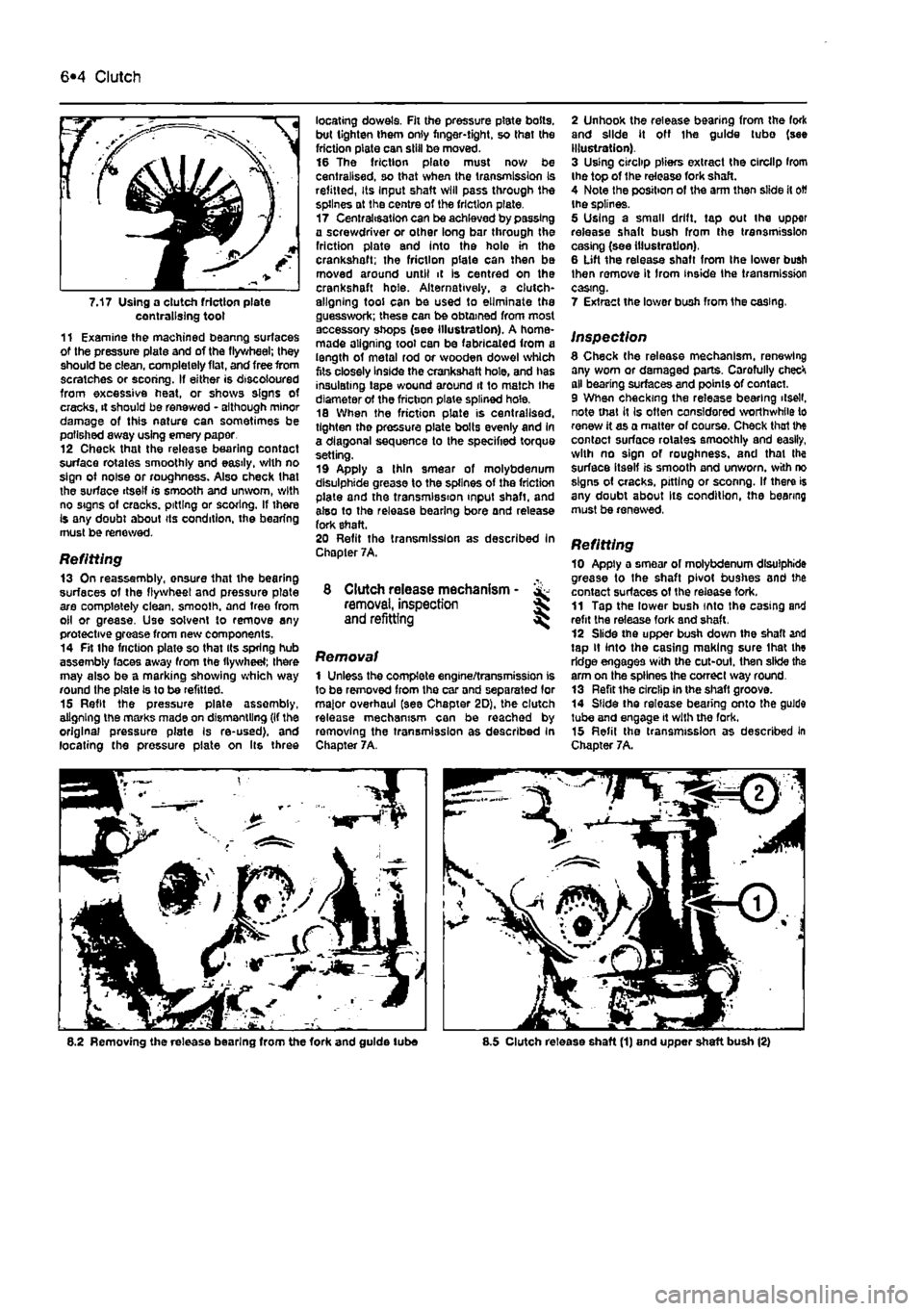
7.17 Using a clutch friction plate centralising toot 11 Examine the machined beanng surfaces of the pressure plate and of the flywheel; they should be clean, completely flat, and free from scratches or scoring. If either is discoloured from excessive heat, or shows signs of cracks, it should be renewed - although minor damage of this nature can sometimes be polished away using emery paper 12 Check that the release bearing contact surface rotates smoothly and easily, with no sign of noise or roughness. Also check that the surface itself is smooth and unworn, with no signs of cracks, pitting or scoring. If there Is any doubt about its condition, the bearing must be renewed.
Refitting 13 On reassembly, onsure that the bearing surfaces of the flywheel and pressure plate are completely clean, smoolh. and tree from oil or grease. Use solvent to remove any protective grease from new components. 14 Fit the friction plate so that its spring hub assembly faces away from the flywheel; there may also be a marking showing which way round the plate Is to be refitted. 15 Refit the pressure plate assembly, aligning the marks made on dismantling (If the original pressure plate Is re-used), and locating the pressure plate on Its three
locating dowels. Fit the pressure plate bolts, but tighten them only finger-tight, so thai the friction plate can skill be moved. 16 The friction plate must now be centralised, so that when the transmission Is refitted, Its Input shaft will pass through the splines at the centre of the friction plate. 17 Centralisation can be achieved by passing a screwdriver or other long bar through the friction plate and into the holo in the crankshaft; the friction plate can then be moved around until it is centred on the crankshaft hole. Alternatively, a clutch-aligning tool can be used to eliminate the guesswork; these can be obtained from most accessory shops (see illustration). A home-made aligning tool can be fabricated from a length of metal rod or wooden dowel which fits closely Inside the crankshaft hole, and has insulating tape wound around it to match Ihe diameter of the friction plate splined hole. 18 When the friction plate is centralised, tighten tho pressure plate bolts evenly and In a diagonal sequence to the specified torque setting. 19 Apply a Ihin smear of molybdenum dlsulphide grease to the splines of the friction plate and the transmission input shaft, and also to the release bearing bore and release fork shaft. 20 Refit the transmission as described In Chapter 7A.
8 Clutch release mechanism - & removal, inspection J and refitting ^
Removal 1 Unless the complete engine/transmission is to be removed from the car and separated lor major overhaul (see Chapter 2D), the clutch release mechanism can be reached by removing the transmission as described In Chapter 7A.
2 Unhook the release bearing from the fork and slide it off Ihe guide tubo (see illustration). 3 Using circlip pliers extract the circllp Irom the top of the release fork shaft. 4 Note the position of the arm then slide it
oW
the splines. 5 Using a small drift, tap out the upper release shaft bush from the transmission casing (see illustration). 6 Lift the release shaft from Ihe lower bush then remove it Irom inside Ihe transmission casing.
7 Extract the lower bush from 1he casing.
inspection 8 Check (he release mechanism, renewing any worn or damaged parts. Carofully checH all bearing surfaces and points of contact. 9 When checking the release bearing ilsell. note that it Is often considered worthwhile to renew it as a matter of course. Check thai the contact surface rotates smoothly and easily, with no sign of roughness, and that Ihe surface itself is smooth and unworn, with no signs of cracks, pitting or sconng. If there is any doubt about Its condition, the bearing must be renewed, Refitting 10 Apply a smear of molybdenum dlsulphide grease to the shaft pivot bushes and the contact surfaces of the release fork. 11 Tap the lower bush into the casing and refit the release fork and shaft. 12 Slide the upper bush down the shaft and tap it into the casing making sure lhat the ridge engages with the cut-out. then slide the arm on the splines the correct way round. 13 Refit the circlip in the shaft groove. 14 Slide the release bearing onto the guide tube and engage it with the fork. 15 Refil the transmission as described in Chapter 7A.
8.2 Removing the release bearing from the fork and guide lube 8.5 Clutch release shaft (1) and upper shaft bush (2)
Page 162 of 225
7A»1
Chapter 7 Part A:
Manual transmission
Contents
Gearchange lever and linkage - removal and refitting 2 General information 1 Manual transmission oil level check See Chapter 1A or 18 Manual transmission oil renewal See Chapter 1A or 1B
Manual transmission overhaul • general information 4 Manual transmission • removal and refitting 3 Reversing light switch • testing, removal and refitting 5
Degrees of difficulty
Easy, suitable
for Faiity
easy,
suitable FaMycffficult, ^ Difficult,
sutable fa-
Verycfifficutt, ^
novice with
little
1
for beginner with suitable
for
competent experienced DIY * * < siitable
for
expert
DIY
jR or professional ^ experience 1
some
experience DIYmechanic ^ mechanic * * < siitable
for
expert
DIY
jR or professional ^
Specifications
General Type
Designation: 1108 cc petrol engine 1242 cc petrol engine Non-turbo diesel engine Turbo diesel engine
Torque wrench settings Gear lever support nut Gear lever to mounting Reverse gear inhibitor cable to transmission Reversing light switch Selector rod-to-gear lever nut Speedometer drive Transmission-to-engine bolt/nut
Transverse mounted, front wheel drive layout with integral transaxle differential/final drive. 5 or 6 forward speeds, 1 reverse speed
C.S14.5.10 (5-speed) or C.514.6.10 (6-speed) C.514.5.1Q/13 (5-speed) C.514.5.13 (5-speed) C.510.5.17 (5-speed)
Nm Ibftl 6 4 49 36 30 22 40 30 17 13 12 9 es 63
1 Genera) Information
The transmission is contained In a cast-aluminium alloy casing bolted to the engine's left-hand end, and consists of the gearbox end final drive differential, Drive Is transmitted from the crankshaft via the clutch to the Input shaft, which has a spiined extension to accept the clutch friction
plate, and rotates in roller bearings at its right-hand end and ball bearings at its left-hand end (on 6-speed versions the left-hand extension rotates In a roller bearing). From the input shaft, drive is transmitted to tho output shaft, which rotates In roller bearings at Its right-hand end. and ball bearings at its left* hand end (on 6-speed versions the left-hand extension rotates in ball bearings). From the output shaft, the drive is transmitted to the differential crownwheel, which rotates with the differential case and gears in taper roller bearings, thus driving the sun gears and
driveshafts. The rotation of the differential gears on their shaft allows the inner roadwheel to rotate at a slower speed than the outer roadwheel when the car is cornering. The Input and output shaftB are arranged side by side, parallel to the crankshaft and driveshafts, so that their gear pinion teeth are In constant mesh. In the neutral position, the relevant input shaft and output shaft gear pinions rotate freely, so that drive cannot be transmitted to the output shaft and crownwheel.
Page 163 of 225
7A*2 Manual transmission
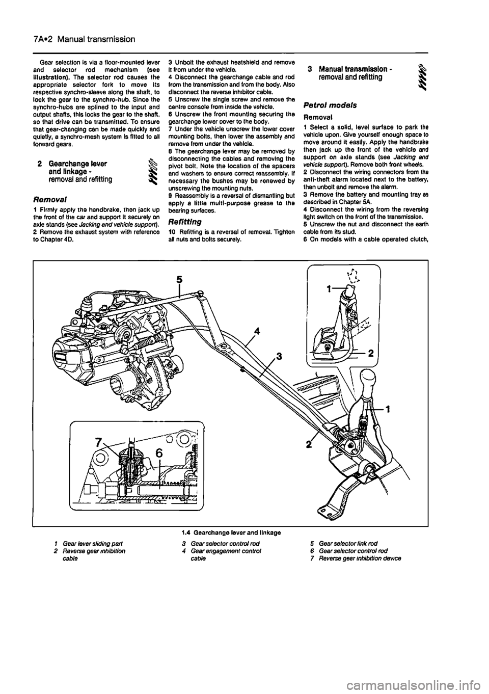
Gear selection is via a floor-mounted lever and selector rod mechanism (seo Illustration). The selector rod causes the appropriate selector fork to move its respective synchro-sleeve along the shaft, to lock the gear to the synchro-hub. Since the synchro-hubs are splined to the Input and output shafts, this locks the gear to the shaft, so that drive can be transmitted. To ensure that gear-changing can be made quickly and quietly, a synchro-mesh system Is fitted to all forward gears,
2 Gearchange lever and linkage -
removal and refitting ^
Removal 1 Firmly apply the handbrake, then jack up the front of the car and support It securely on axle stands {see Jacking and veh/cte support). 2 Remove the exhaust system with reference to Chapter 4D.
3 Unbolt the exhaust heatshield and remove It from under the vehicle. 4 Disconnect the gearchange cable and rod from the transmission and from the body. Also disconnect the reverse inhibitor cable. 5 Unscrew the single screw and remove the centre console from inside the vehicle. 6 Unscrew the front mounting securing the gearchange lower cover to the body. 7 Under Ihe vehicle unscrew the lower cover mounting bolts, then lower Ihe assembly and remove from under the vehlole. 8 The gearchange lever may be removed by disconnecting the cables and removing the pivot bolt. Note the location of the spacers and washers to ensure correct reassembly. If necessary the bushes may be renewed by unscrewing the mounting nuts. 9 Reassembly is a reversal of dismantling but apply a little multi-purpose grease to the bearing surfaces.
Refitting 10 Refitting is a reversal of removal. Tighten all nuts and bolts securely.
3 Manual transmission - & removal and refitting § S
Petrol models
Removal 1 Select a solid, level surlace to park the vehicle upon. Give yourself enough space to move around it easily. Apply the handbrake then jack up the front of the vehicle and support on axle stands (see Jacking and vehicle support). Remove both front wheels. 2 Disconnect the wiring connectors from (he anti-theft alarm located next to the battery, then unbolt and remove the alarm. 3 Remove the battery and mounting tray as described in Chapter 5A. 4 Disconnect the wiring from the reversing light switch on the front of the transmission. 5 Unscrew the nut and disconnect the earth cable from its stud. 6 On models with a cable operated clutch,
1.4 Gearchange lever and linkage 1 Gear lever sliding part 3 Gear selector control rod 5 Gear selector link rod 2 Reverse gear inhibition 4 Gear engagement control 6 Gear selector control rod cable cable 7 Reverse gear inhibition device
Page 165 of 225
7A«4 Manual transmission
33 Remove lha air cleaner front section and air ducting with reference to Chapter 4C. Also disconnect the injection pump vacuum pipe from the clips on the left-hand end of the cylinder head. This work is necessary in order to fit the engine hoist 34 Support the weight of the engine using a hoist attached to the engine lifting eyes, or alternatively use a trolley Jack and block of wood beneath the engine. 35 Unscrew the nuts securing the downpipe to the exhaust manifold, then lower it and support on an axle stand. Recover the gasket. 36 Unscrew the starter motor mounting bolts and support the starter motor to one side. 37 Disconnect the wiring from the reversing light switch on the front of the transmission. 38 Unscrew the nut and disconnect the earth cable from its stud. 39 Trace the wiring back from the electronic speedometer sensor and disconnect the connector located on the left-hand side ot the engine. If a mechanical speedometer Is fitted unscrew the knurled collar and disconnect the cabte from the transmission. 40 Unbolt and remove the transmission lower cover. 41 Using an Allen key unscrew the bolts securing the inner end of the left-hand driveshaft to the transmission flange. Remove the bolts and recover the spacer plates. Support the driveshaft on an axle stand. 42 Unscrew and remove the bolts securing the left-hand swivel hub assembly to the front suspension strut, then separate the components and support the swivel hub on an axle stand. 43 Move the swrvel hub assembly outwards and support the driveshaft away from Ihe transmission. 44 Using an Allen key unscrew the bolts securing the Inner end of the right-hand driveshaft to the intermediate shaft flange. Remove the bolts and recover the spacer plates. Support the driveshaft on an axle stand. 45 Remove the intermediate driveshaft with reference to Chapter 8. 46 Working beneath the vehicle, unscrew the bolts securing the rear engine mounting to the underbody then unscrew the bolts securing the mounting to the transmission and withdraw the mounting assembly from under the vehicle.
47 Unscrew the bolts securing the left-hand engine/transmission mounting to the body then unscrew Ihe bolts from the transmission and remove the mounting. 48 Support the weight of the transmission on a trolley jack then unscrew the remaining nut and bolts from the bellhousing and pull the transmission away from the engine.
A
Warning: Support the trans-mission to ensure that It remains steady o/i the jack head. Keep the transmission level until the Input shaft
1$
fully withdrawn from the clutch friction plate.
Refitting 48 Refitting is a reversal of the removal procedure, but note the following points. a) Appiy a smear* of high-meiting-point grease to the clutch friction piate splines; take care to avoid contaminating the friction surfaces. b) Tighten all bolts to the specified torque. c) Fit new clips to secure the driveshaft gaiters to the transmission output shafts. d) Adjust the clutch cable (where applicable) as described In Chapter 6.
4 Manual transmission overhaul -general Infomtatlon
Overhauling a manual transmission is a difficult and Involved Job for the DIY home mechanic. In addition to dismantling and reassembling many small parts, clearances must be precisely measured and, if necessary, changed by selecting shims and spacers. Internal transmission components are also often difficult to obtain, and in many Instances, extremely expensive. Because of this, If the transmission develops a fault or becomes noisy. Ihe best course of action is to have the unit overhauled by a specialist repairer, or to obtain an exchange reconditioned unit. Nevertheless, it is not impossible for the more experienced mechanic to overhaul the transmission, provided the special tools are available, and the Job is done in a deliberate step-by-step manner, so that nothing is overlooked.
The tools necessary for an overhaul include internal and external clrclip pliers, bearing pullers, a slide hammer, a sat of pin punches, a dial test Indicator, and possibly a hydraulic press. In addition, a large, sturdy workbench 8od a vice will be required. During dismantling o1 the transmission, make careful notes of how each component
1$
fitted, to make reassembly easier and more accurate. Before dismantling the transmission, it will help if you have some idea what area is malfunctioning. Certain problems can be closely related to specific areas In the transmission, which can make component examination and replacement easier. Refer to the Fault Finding Section at the end of this manual for more Information.
5 Reversing light switch -testing, removal and refitting ||
Testing 1 The reversing light circuit is controlled by a plunger-type switch screwed into the front of the transmission casing. If a fault develops, first ensure that Ihe circuit fuse has not blown. 2 To test the switch, disconnect the wiring connector, and use a multimeter (set to the resistance function) or a battery-and-bulb test circuit to check that there is continuity between the switch terminals only when reverse gear is selected. If this is not the case, and there are no obvious breaks or other damage to the wires, the switch is faulty, and must be renewed.
Removal 3 Access to the reversing light switch Is best achieved from under the vehicle. Apply the handbrake then jack up Ihe front of the vehicle and support on axle stands (see Jacking and vehicle support). 4 Disconnect the wiring connector, then unscrew It from the transmission casing.
Refitting 5 Refit the switch and tighten securely. 6 Reconnect the wiring then lower the vehicle to the ground.
Page 169 of 225
7B*4 Automatic transmission
2 Automatic transmission - ^ removal and refitting St
Removal 1 Select a solid, level surface to park the vehicle upon. Give yourself enough space to move around it easily. Apply the handbrake then jack up the front of the vehicle and support on axle stands (see Jacking and vehicle support). Remove both front wheels, 2 Remove the battery and mounting tray as described In Chapter 5A. 3 Remove the air cleaner and air inlet duct as described In Chapter 4A. 4 Disconnect the kickdown cable at the sector on the throttle housing and detach It from the mounting on the camshaft cover. Also release the cable from the support on the left-hand end of the cylinder head. 5 Disconnect the wiring connectors on the transmission. 6 Disconnect the fluid inlet and outlet Unas from the heat exchanger on top of the transmission. 7 Pull the fluid level dipstick from Its tube on the front of the transmission and tape over the top of the tube to prevent dirt entry. 8 Unscrew and remove the retaining pin and disconnect the speed selector cable from the top of the transmission. 9 Unscrew the upper bolt securing the starter motor to the transmission. 10 Unscrew the upper bolts securing the transmission to the engine. 11 Support the weight of the engine using a hoist attached to the engine lifting eyes, or alternatively UBO a trolley jack and block of wood beneath the engine, 12 Remove the screws and remove the front wheel arch liner from under the left-hand wheel arch. 13 Unscrew the nut securing the earth cablo to the transmission. 14 Using a punch drive out the roll pins securing both driveshafts to the final drive output shafts. 15 Unscrew and remove the bolts securing the left-hand swivel hub assembly to the front suspension strut, then separate the components and support the swivel hub on an axle stand. 16 Move the swivel hub assembly outwards and slide the inner end of the driveshaft from the splines on the transmission output shaft. Support the shaft away from the transmission to prevent damage to the gaiters. 17 Unscrew the lambdafoxygen sensor from the exhaust downpipe and position it In a safe place to prevent damage. 18 Unscrew ihe nuts securing the downpipe to Ihe exhaust manifold, then lower It and suppon on an axle stand. Recover the gasket. 19 Unscrew the knurled nut and disconnect the speedometer cable from the top of the final drive housing.
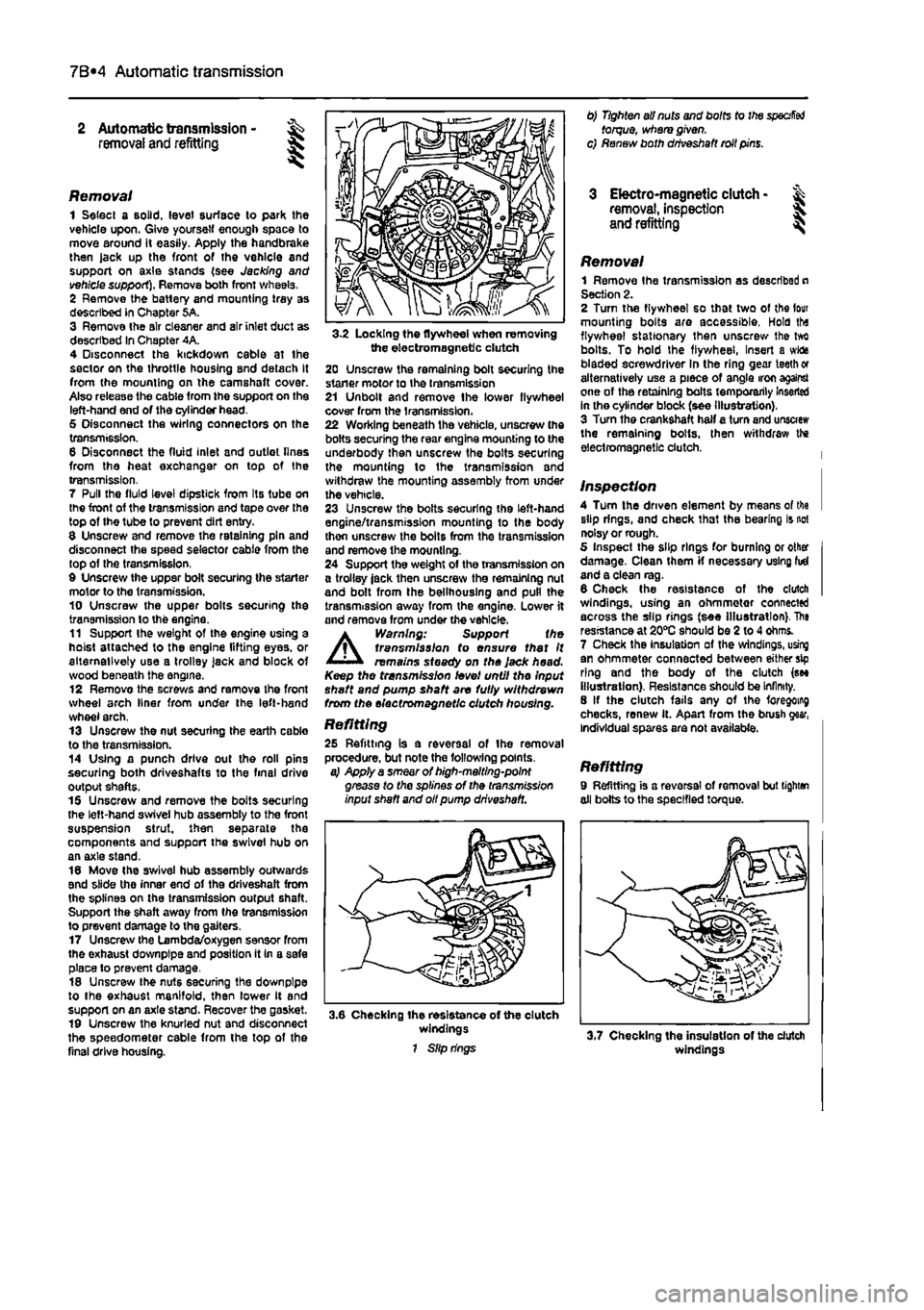
3-2 Locking the flywheel when removing the electromagnetic clutch 20 Unscrew the remaining bolt securing the staner motor to the transmission 21 Unbolt and remove Ihe lower flywheel cover from the transmission. 22 Working beneath the vehicle, unscrew the bolts securing the rear engine mounting to the underbody then unscrew the bolts securing the mounting lo the transmission and withdraw the mounting assembly from under the vehicle. 23 Unscrew the bolts securing the left-hand engine/transmission mounting to the body thon unscrew the bolts from the transmission and remove the mounting. 24 Support the weight of the transmission on a trolley jack then unscrew the remaining nut and bolt from the bellhouslng and pull the transmission away from the engine. Lower it and remove from under the vehicle.
A
Warning: Support the transmission to ensure that It remains steady on the Jack head. Keep the transmission level until the Input shaft and pump shaft are fully withdrawn from the electromagnetic clutch housing.
Refitting 25 Refitting is a reversal of the removal procedure, but note the following points. a} Apply a smear of high-melting-point grease to the splines of the transmission input shaft and oil pump driveshaft.
3.6 Checking the resistance of the clutch windings 1 Slip rings
0) Tighten all nuts and bolts to the
specified
torque, where given, c) Renew both driveshaft roll pins.
3 Electro-magnetic clutch • & removal, inspection 5. and refitting ^
Removal 1 Remove Ihe transmission as described n Section 2. 2 Turn the flywheel so that two of the lour mounting bolts are accessible, Hold tha flywheel stationary then unscrew Ihe tvrt bolts. To hold the flywheel, Insert a wida bladed screwdriver In the ring gear teeth or alternatively use a piece of angle iron against one of the retaining bolts temporarily Inserted in the cylinder block (see illustration). 3 Turn the crankshaft half a turn and unscrew the remaining bolts, then withdraw the electromagnetic clutch.
Inspection 4 Turn the driven element by means of tha slip rings, and check that the bearing is not noisy or rough. 5 Inspect the slip rings for burning or other damage. Clean them if necessary using fid and a clean rag. 6 Check the resistance of the clutch windings, using an ohmmetor connected across the slip rings (see Illustration). The resistance at 20*0 should be 2 to 4 ohms. 7 Check the Insulation of the windings, using an ohmmeter connected between either sip ring and the body of the clutch (see illustration). Resistance should be Infinity. 8 If the clutch fails any of the foregoing checks, renew it. Apart from the brush gear, Individual spares are not available.
Refitting 9 Refitting is a reversal of removal but tighten all bolts to the specified torque.
windings
Page 172 of 225
6*172
Chapter 8
Driveshafts
Contents
Oriveshaft gaiter check See Chapter 1A or 1B General information 1 Oriveshaft overhaul and rubber gaiter renewal 3 intermediate driveshaft - removal and refitting 4 Driveshafts - removal and refitting 2
Degrees of difficulty
Easy,
suitable for ^ novtoewithittle experience ^
Fatly
easy,
suitable for beginner with
some experience
^
Fairty
difficult, suitable
tor
competent OtYmechanlc
Difficult,
suitable for experienced DIY mechanic ^
Veiydfficult, ^
suitable
for
expert DIY
or professional ^
Specifications
General Type
Lubrication lubricant type
Torque wrench settings Driveshaft nut* All models except turbo diesel (M22 plain) Turbo diesel (M24 with staking and captive washer) Roadwheel bolts Suspension strut-to-hub carrier bolts Track-rod balljolnt-to-hub carrier 'Use a new nut.
Unequal-length, solid steel shafts, splined to Inner and outer constant velocity joints. Intermediate shaft with support bearing on turbo diesel models with equal length driveshafts.
Fiat specification grease, supplied with gaiter repair kit
Nm Ibfft
240 177 280 207 85 63 70 52 40 30
1 General information
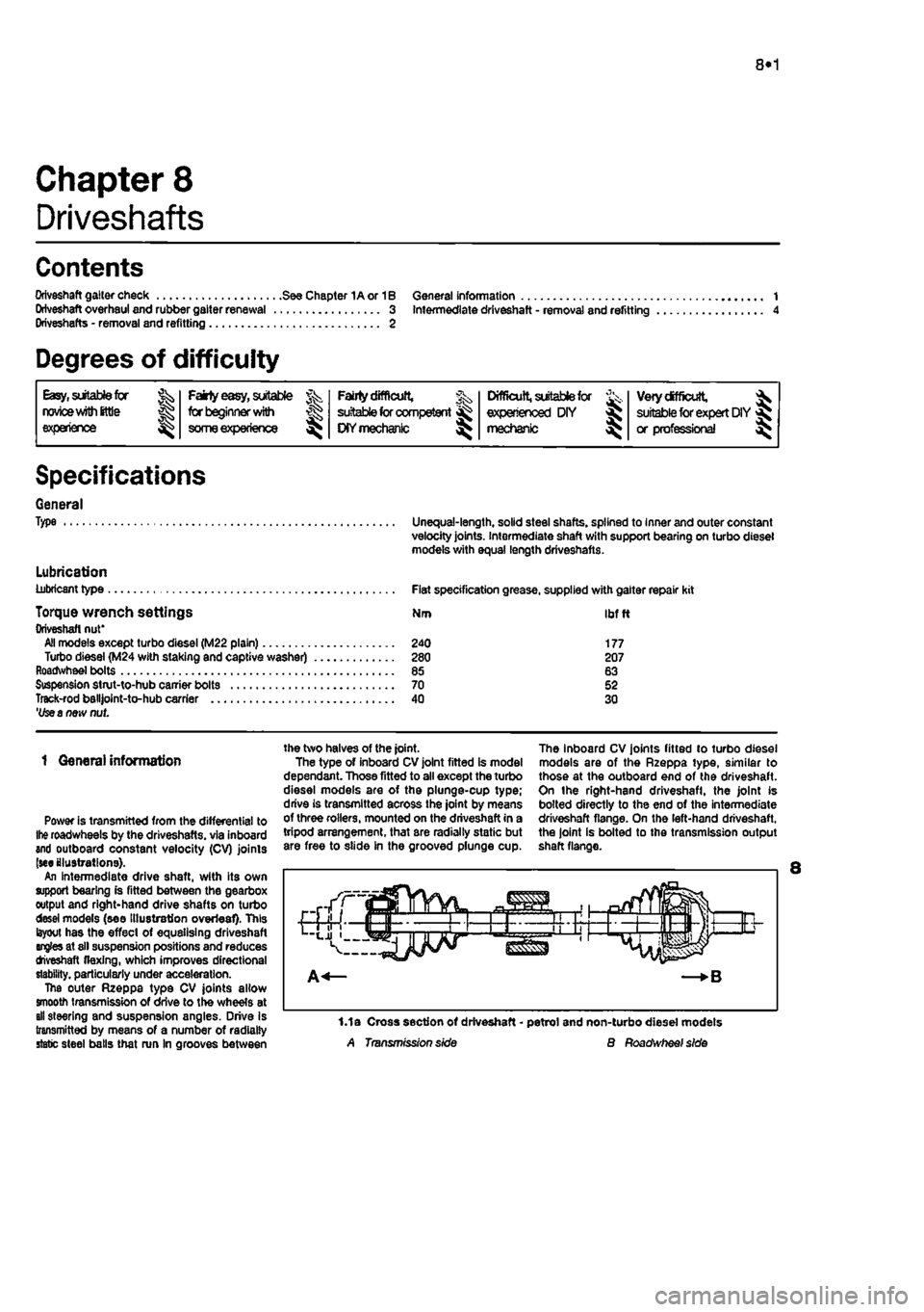
Power is transmitted from the differential to
Ihe
roadwheels by the driveshafts. via inboard and outboard constant velocity (CV) joints (we illustrations). An intermediate drive shaft, with its own support bearing is fitted between the gearbox output and right-hand drive shafts on turbo desei models (see Illustration overleaf). This layout has the effect of equalising driveshaft angles at sll suspension positions and reduces tfveshaft flexing, which improves directional stability, particularly under acceleration. The outer Rzeppa type CV joints allow smooth transmission of drive to the wheels at all steering and suspension angles. Drive Is transmitted by means of a number of radially static steel balls that run In grooves between
the two halves of the joint. The type of inboard CV joint fitted is model dependant. Those fitted to all except the turbo diesel models are of the plunge-cup type; drive is transmitted across the joint by means of three rollers, mounted on the driveshaft in a tripod arrangement, that are radially static but are free to slide in the grooved plunge cup.
The inboard CV joints fitted to turbo diesel models are of the Rzeppa type, similar to those at the outboard end of the driveshaft. On the right-hand driveshafl, the joint is bolted directly to the end of the intermediate driveshaft flange. On the left-hand driveshaft, the joint is bolted to the transmission output shaft flange.
1.1a Cross section of driveshaft - petrol and non-turbo diesel models A Transmission side B Roadwheef side
Page 173 of 225
8*2 Driveshafts
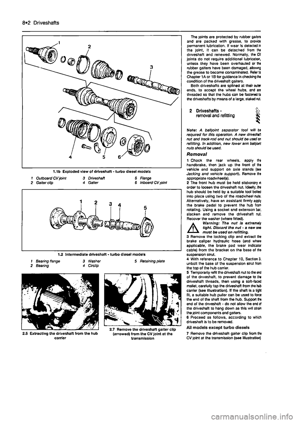
f Outboard CV joint 3 Driveshaft 6 Flange 2 Gaiter clip A Garter 6 Inboard CV ioint
1.2 Intermediate driveshaft • turbo diesel models 1 Bearing flange 3 Washer S Retaining plate 2 Bearing A Circllp
2.S Extracting the driveshaft from the hub (arrowed) from the CV joint at the carrier transmission
The joints are protected by rubber g&itcrs and are packed with grease, to orovktt permanent lubrication. If wear Is detected in the joint. It can be detached from lii» driveshaft and renewed. Normally, the CV joints do not require additional lubrication, unless they havo been overhauled or lfi» rubber gaiters have been damaged, allotting the greasa to become contaminated. Rater
to
Chapter 1A or 1B for guidance In checking the condition of the driveshaft gaiters. Bolh driveshafts are splined at their outer ends, to accept the wheel hubs, ond ate threaded so that the hubs can be fastened to the driveshafts by means of a large, staked nut.
2 Driveshafts -removal and refitting & ^
Note: A balljoint separator tool will b» required for this operation. A new drivestnf, nut and tmck-rod end nut should be used
on
refitting. In addition, new lower arm
baHj&ot
nuts should be used. Removal 1 Chock the rear wheels, apply the handbrake, then jack up the front of tha vehicle and support on axle stands (see Jacking and vehicle support). Remove th« appropriate roadwheel(6). 2 The front hub must be held stationary
m
order to loosen the driveshaft nut. Ideally, M hub should be held by a suitable tool bolted Into placo using two of the roadwheel nuts, Alternatively, havo an assistant firmly apply the brake pedal to prevent the hub from rotating. Using e socket and extension bar, slacken and remove the driveshaft nut. Recover the washer (where fitted).
A
Warning: The nut Is extremely tight. Discard the nut - a new
one
must be used on refitting. 3 Remove the locking clip and extract the brake caliper hydraulic hose (and where applicable, the brake pad wear indicator cable) from the bracket on the base of the suspension strut. 4 With reference to Chapter 10, Section 3. unbolt the base of the suspension strut from Ihe top of the hub carrier. 5 Temporarily refit the driveshaft nut to the end of the driveshaft, to prevent damage to the driveshaft threads, then using a solt-faced mallet, carefully tap the driveshaft from the hub carrier (see illustration). If the shaft is a tight fit, a suitable hub puller can be used to force the end of the shaft from the hub. Support tha end of the driveshaft • do not allow the end o the driveshaft to hang down as this svill strain the joint components and gaiters. 6 Proceed as follows, according to which driveshaft is to be removed. All models except turbo diesels 7 Remove the driveshaft gaiter clip from the CV joint at the transmission (see Illustration)
Page 175 of 225
I
8*4 Driveshafts
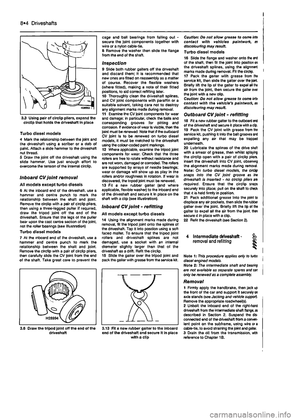
3.3 Using pair of circlip pliers, expand the circlip that holds the driveshaft in place
Turbo diesel models 4 Mark the relationship between the joint and the driveshaft using a scriber or a dab of paint. Attach a slide hammer to the dnveshaft nut thread. 5 Draw the joint off the driveshaft using the slide hammer, Use just enough effort to overcome the tension of the internal circlip.
Inboard CV joint removal All models except turbo dieseis 6 Al the inboard end of the driveshaft. use a hammer and centre punch to mark the relationship between Ihe shaft and |olnt. Remove the circlip with a pair of circlip pliers, then using a three-legged puller if required, draw Ihe tripod joint off the end of the driveshaft. Ensure that the legs of Ihe puller bear upon the cast centre section of the joint, not the roller beanngs (see illustration) Turbo diesel models 7 Al the inboard end of Ihe driveshaft. use a hammer and centre punch lo mark the relationship between the shaft and joint. Remove the circlip with a pair of circlip pliers, then carefully slide the CV joint from the end ot the shaft. Take great care to prevenl the
cage and bail bearings from falling out • secure the joint components together with wire or a nylon cable-tie. 8 Remove the washer then slide the flange from the end of the shaft.
Inspection 9 Slide both rubber gaiters off the driveshaft and discard them: It is recommended that new ones are fitted on reassembly as a matter of course. Recover the flexible washers (where fitted), making a note of their fitted positions, to aid correct refitting later. 10 Thoroughly clean the driveshaft splines, and CV joint components with paraffin or a suitable solvent, taking care not to destroy any alignment marks made during removal. 11 Examine Ihe CV joint components for wear and damage: in particular, check the balls and corresponding grooves for pitting and corrosion. If evidence of wear Is visible, then the joint must be renewed. Note that if the outboard CV joint Is to be renewed on turbo diesel models, it must be matched to the driveshaft using the colour-coded paint markings. 12 Where applicable, examine the tripod joint components for wear. Check thai the three rollers are free lo rotate without resistance and are not worn, damaged or corroded. The rollers are supported by arrays of needle bearings: wear or damage will show up as play In the rollers and/or roughness in rotation. If wear is discovered, the tnpod joint must be renewed. 13 Fit a new rubber gaiter (and where applicable, flexible washer) to the inboard end of the driveshaft and secure it In place on the shaft with a clip (see illustration).
Inboard CV joint - refitting
All models except turbo dieseis 14 Using Ihe alignment marks made during removal, fit the tripod joint onto the splines of the driveshaft. Tap It Into position using a soft faced mallet. To ensure that the tripod Joint rollers and driveshaft splines are not damaged, use a socket with an internal diameter slightly larger than I hat of the driveshafl as a drift. Refit the circlip. 15 Slide the gaiter over tho tripod joint and pack the gaiter with grease from the service kit.
3.6 Draw the tripod joint off the end of the driveshaft 3.13 FH s new rubber gaiter to the inboard end of the driveshaft and secure It in place with a clip
Caution: Do not allow grease to come
into
contact with vehicles paintwork, es discolouring may rasutt. Turbo diesel models 16 Slide the flange and washer onto the end of the shaft, then fit the joint Into position on the driveshaft splines, using the alignment marks made during removal. Fit the circlip. ' 17 Pack the gaiter with grease from His service kit, then slide the gaiter over the joint. Briefly lift the lip of the gaiter to expel ail the air from the joint, then secure the gaiter over the joint with a new clip. Caution: Do not allow grease to come
Into
contact with the vehicle's paintwork, as discolouring may result.
Outboard CV joint - refitting 18 Fit a new rubber gaiter to the outboard end of the driveshaft and secure it place with a dp, 19 Pack the CV joint with grease from Ihe service kit, pushing It into the ball grooves and expelling any air that may be trapped underneath. 20 Lubricate the splines of the drive shaft with a smear of grease, then whilst splaying the circlip open with a pair ot circlip pile*, insert the driveshaft into CV joint, observing the alignment marks made during removal. Note: On turbo diesel models, the circlip snaps into the CV Joint groove as Ifte driveshaft is inserted - no circlip pliers are required. Ensure that the circlip snaps securely Into place: pull on the shaft to check that it is held firmly In position. 21 Pack additional grease Into the joint to displace any air pockets, then slide the rubber gaiter over the joint. Briefly lift the lip ol the gaiter to expel all the air from Ihe joint, then secure it In place with a clip. 22 Refit the driveshaft (see Section 2).
4 Intermediate driveshaft - % removal and refitting J;
Note 1: This procedure applies only to turbo diesel engined models. Note 2: The intermediate shaft and
bearing
are not available as separate spares and cac only be renewed as a comptefe assembly.
Removal 1 Firmly apply the handbrake, then jack up the front of Ihe car and support It securely
on
axle stands (see Jacking and vehicle support). Remove the appropriate roadwheei(s). 2 Unbolt the inboard end of the right*hand driveshaft from the intermediate shaft
flange, as
described In Section 2. Suspend the dis-connected end of the driveshaft from a conven-ient point on the subframe, using wire or a cable-tie. to avoid straining the joint and gaiter. 3 Drain the oil from the transmission, with reference to Chapter 1B.
Page 176 of 225
Driveshafts 8*5
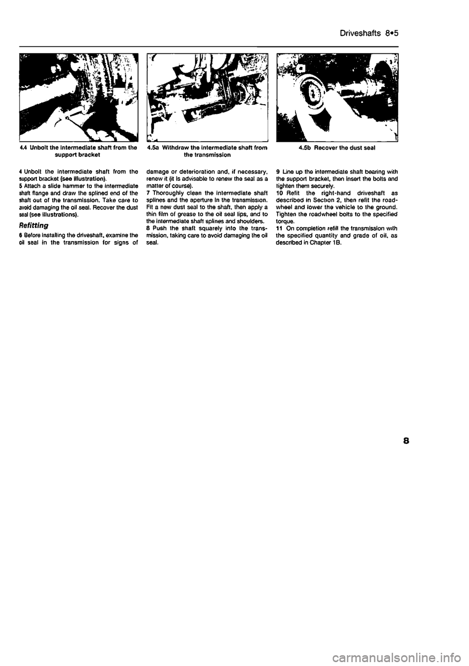
4.4 Unbolt the Intermediate shaft from the 4.5a Withdraw the intermediate shaft from support bracket the transmission 4.5b Recover the dust seal
4 Unbolt the intermediate shaft from the support bracket (see Illustration). 5 Attach a slide hammer to the intermediate shaft flange and draw the splined end of the shaft out of the transmission. Take care to avoid damaging the oil seal. Recover the dust seal (see illustrations).
Refitting 6 Before installing the driveshaft, examine the oil seal in the transmission for signs of
damage or deterioration and, if necessary, renew it (it is advisable to renew the seal as a matter of course). 7 Thoroughly- clean the intermediate shaft splines and the aperture In the transmission. Fit a new dust seal to the shaft, then apply a thin film of grease to the oil seal lips, and to the intermediate shaft splines and shoulders. 8 Push the shaft squarely into the trans-mission, taking care to avoid damaging the oil
9 Line up the intermediate shaft bearing with the suppori bracket, then insert the bolls and tighten them securely. 10 Refit the right-hand driveshaft as described in Section 2, then refit the road-wheel and lower the vehicle to the ground. Tighten the roadwheel bolts to the specified torque. 11 On completion refill the transmission with the specified quantity and grade of oil. as described in Chapter 1B.
8