specified torque FIAT PUNTO 1998 176 / 1.G Repair Manual
[x] Cancel search | Manufacturer: FIAT, Model Year: 1998, Model line: PUNTO, Model: FIAT PUNTO 1998 176 / 1.GPages: 225, PDF Size: 18.54 MB
Page 200 of 225

10*12 Suspension and steering
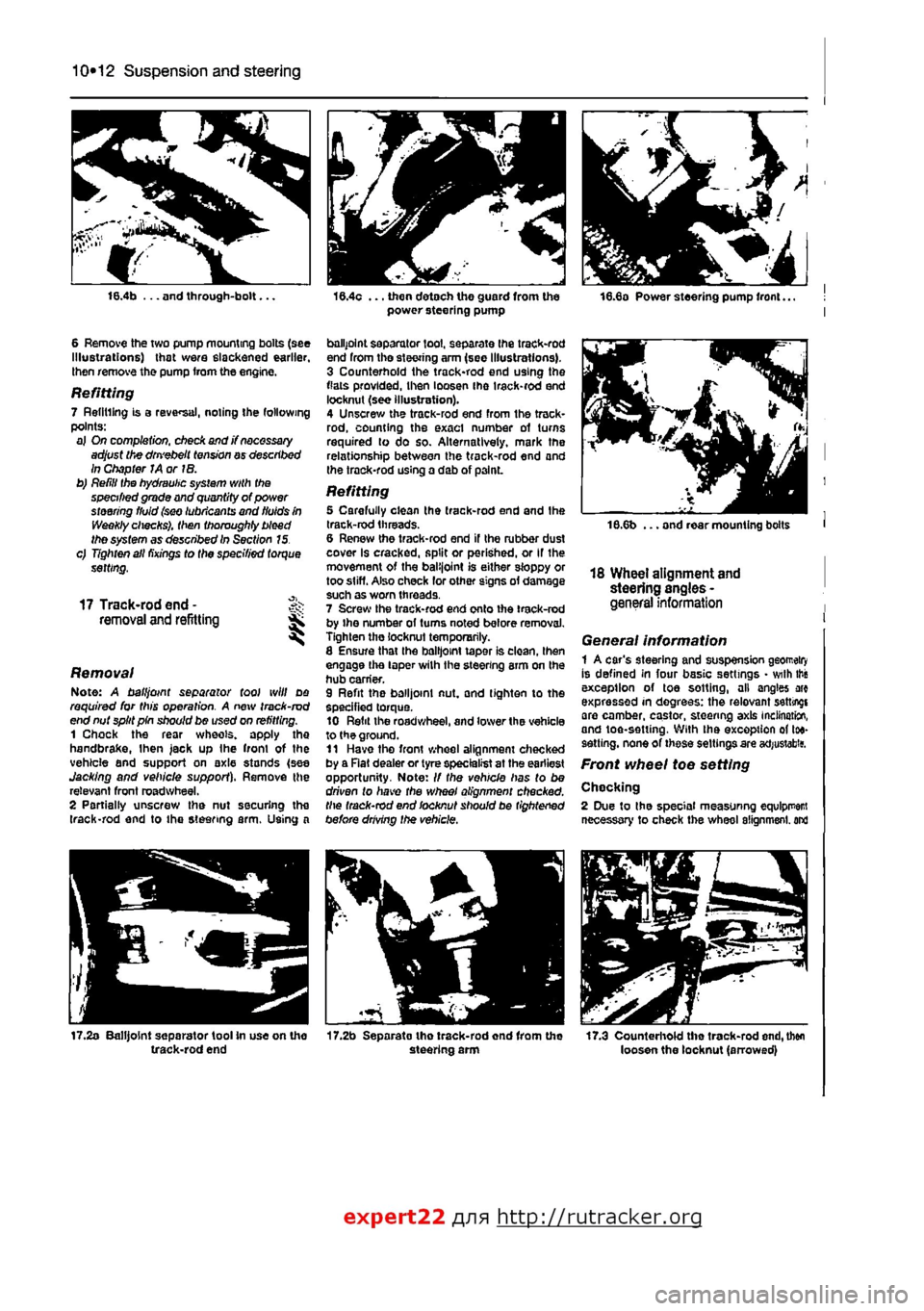
16.4b ... and through-bolt...
6 Remove the two pump mounting bolts (see Illustrations) that were slackened earlier, then remove the pump from the engine.
Refitting 7 Refilling is a reversal, noting the following points: a) On completion, check and j? necessary adjust the dm'ebelt tension ay described In Chapter JA or IB. b) Refill the hydraulic system with the specified grade and quantity of power steering fluid (sw lubricants and fluids in Weekly checks), then thoroughly bleed the system as described In Section 15. c) Tighten all fixings to the specified torque setting,
17 Track-rod end -removal and refitting ^ S
Removal Note: A ball joint separator tool will do required for this operation. A new track-rod end nut split pin should be used on refitting. 1 Chock the rear wheels, apply the handbrake,
I
hen jack up Ihe front of the vehicle and support on axle stands (see Jacking and vehicle support). Remove the relevant front roadwheel. 2 Partially unscrew the nut securing the (rack-rod end to the steering arm. Using a
17.2a Balljoint separator tool In use on the track-rod end
16.4c ... then detach the guard from the power steering pump
ballpoint separator tool, separate Ihe track-rod end from tho steering arm (see Illustrations). 3 Counterhold the track-rod end using the flats provided, then loosen ihe irack-rod end locknut (see illustration). 4 Unscrew the track-rod end from the track-rod, counting the exact number of turns required to do so. Alternatively, mark the relationship between the track-rod end and the trock-rod using a dab of p3lnL
Refitting 5 Carefully clean the track-rod end and the track-rod threads. 6 Renew the track-rod end if the rubber dust cover Is cracked, split or perished, or If the movement of the balijoint is either sloppy or too stiff. Also check lor other signs of damage such as worn threads. 7 Screw the track-rod end onto ihe track-rod by ihe number ol turns noted before removal. Tighten the locknut temporarily. 8 Ensure that Ihe balljoint taper is clean, then engage the taper wilh the steering arm on the hub carrier. 9 Refit the balljoint nut, and tighten to the specified torque. 10 Refit the roadwheel, and lower the vehicle to the ground. 11 Have tho front wheel alignment checked by a Rat dealer or tyre specialist at the earliest opportunity. Note: // the vehicle has to be driven to have the wheel alignment checked, the track-rod end locknut should be tightened before drMng the vehicle.
17.2b Separato tho track-rod end from the steering arm
18.6b ... and rear mounting bolts
18 Wheel alignment and steering angles -general information
General information 1 A car's steering and suspension geomeiry Is defined in four basic settings • with this exception of toe sotting, all angles arc expressed in degrees: the relevant setting! are camber, castor, steering axis inclination, and toe-setting. With ihe exception of toe-sett ing, none of these settings are acfjustabitf.
Front wheel toe setting
Chocking 2 Due to the special measuring equlpr
expert22 fl/m http://rutracker.org
Page 207 of 225

11
*6 Bodywork and fittings
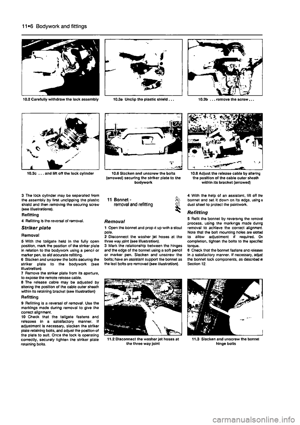
10.3c ... and lift off die lock cylinder
3 The lock cylinder may be separated from the assembly by first uncllpplng the plastic shield and then removing the securing screw (see Illustrations). Refitting 4 Refitting is Ihe reversal of removal.
Striker plate
Removal 5 With the tailgate held In the fully open position, mark the position of the striker plate In relation to the bodywork using a pencil or marker pen, to aid accurate refitting. 6 Slacken and unscrew the bolts securing the striker plate to the bodywork (see Illustration) 7 Remove the striker plate from its aperture, to expose the remote release cable. 8 The release cable may be adjusted by altering the position of Ihe cable outer sheath wKhin its retaining bracket (see illustration) Refitting 9 Refitting is a reversal of removal. Use the markings made during removal to givo Ihe correct alignment. 10 Check that the tailgate fastens and releases in a satisfactory manner. If adjustment Is necessary, slacken the striker plate retaining bolts, and adjust Ihe position ot the plate to suit. Once the lock is operating correctly, securely tighten the striker plate retaining bolls.
10.3a Unclip tho plastic shield... 10.3b ... remove the screw...
10.8 Slackon and unsorew the bolts (arrowed) securing the strfker plate to the bodywork
Si
10,8 Adjust the rolease cable by altering the position of the cable outer sheath within its bracket (arrowed)
11 Bonnet-removal and refitting
Removal 1 Open the bonnet and prop it up with a stout pole. 2 Disconnect the washer Jet hoses at the three way joint (see illustration), 3 Mark the relationship between the hinges and the edge of the bonnet using a soft pencil or markor pen. Slacken and unscrew the bolts: have an assistant support the bonnet as the last bolts aro removed (see Illustration),
4 With the help of an assistant, lift off the bonnet and set it down on its edge, using a dust sheet to protect the paintwork.
Refitting 5 Refit the bonnet by reversing the removal process, using the markings made dunng removal to achieve the correct alignment. Note that the boll mounting holes are slotted to allow adjustment if required. On completion, tighten the bolts to the specified torque. 8 Check that the bonnet fastens and releases in a satisfactory manner. If necessary, adjust the bonnet lock components, as described
m
Section 12.