Eated FIAT PUNTO 1998 176 / 1.G Workshop Manual
[x] Cancel search | Manufacturer: FIAT, Model Year: 1998, Model line: PUNTO, Model: FIAT PUNTO 1998 176 / 1.GPages: 225, PDF Size: 18.54 MB
Page 8 of 225
Roadside repairs 0.7
I Jump starting will get you out of trouble, but you must correct | whatever made the battery go fiat in the first place. There are three possibilities:
t
The battery has been drained by repeated attempts to start, or by leaving the lights on.
2
The charging system (s not working property (alternator drivebelt slack or broken, alternator wiring fault or alternator Itself faulty).
3
The battery Itself is at fault (ehctrotyte low, or battery worn out).
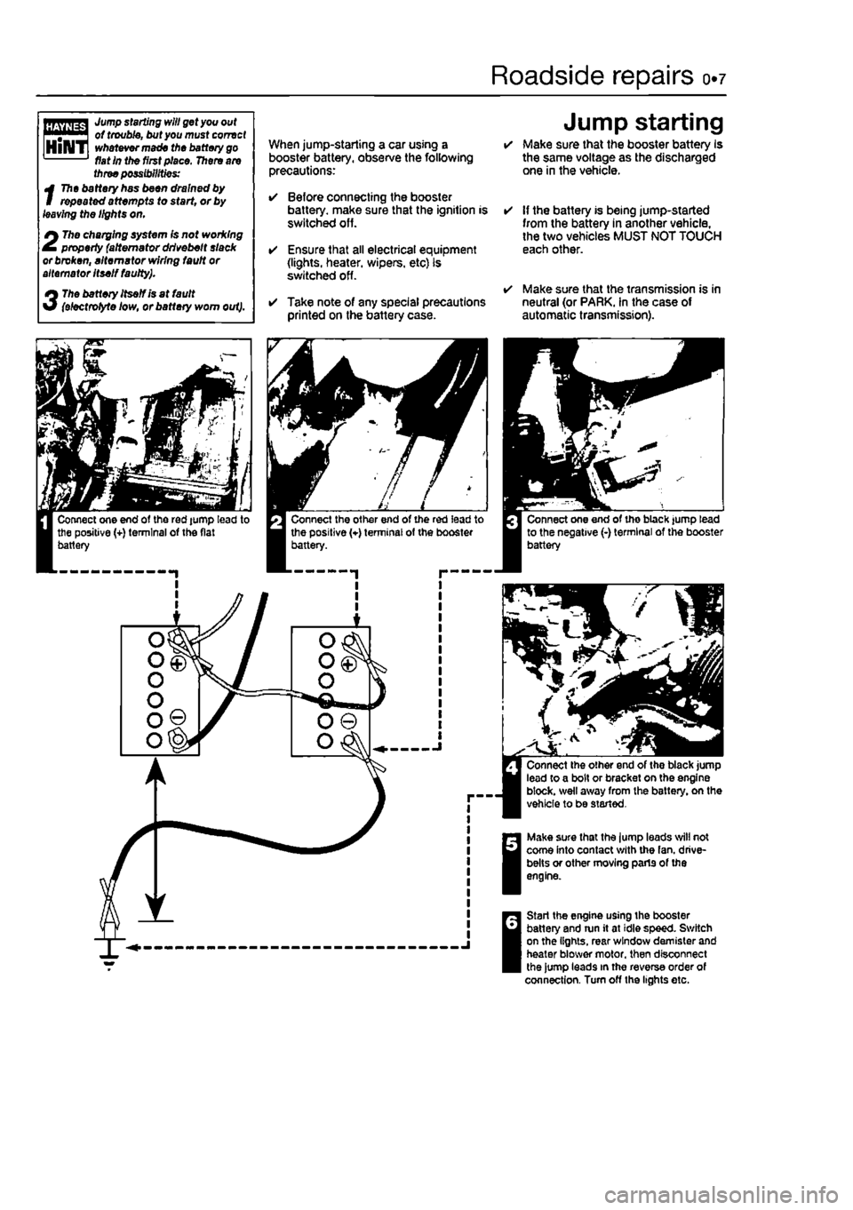
When jump-starling a car using a booster battery, observe the following precautions:
• Before connecting the booster battery, make sure that the ignition is switched off.
• Ensure that all electrical equipment (lights, heater, wipers, etc) is switched off.
• Take note of any special precautions printed on the battery case.
Jump starting • Make sure that the booster battery Is the same voltage as the discharged one in the vehicle.
• If the battery is being jump-started from the battery in another vehicle, the two vehicles MUST NOT TOUCH each other.
• Make sure that the transmission is in neutral (or PARK. In the case of automatic transmission).
Make sure that the lump leads will not come into contact with the fan. drive-belts or other moving parts of the engine.
Start the engine using the booster battery and run it at idle speed. Switch on the lights, rear window demister and heater blower motor, then disconnect the jump leads in the reverse order of connection. Turn off the lights etc.
Page 14 of 225
Weekly checks 0.13
Brake fluid level
A
Warning: • Brake fluid can harm your eyes and damage painted surfaces, so use extreme caution when handling and pouting it.
• Do not use fluid that has been standing open for so mo time, as It absorbs moisture from the air, which can cause a dangerous loss of braking effectiveness.
Mpmna * Make sure that your car Is I on level ground. HiNTi * Th* ffftt 'eve/ In the reservoir will drop slightly as
I
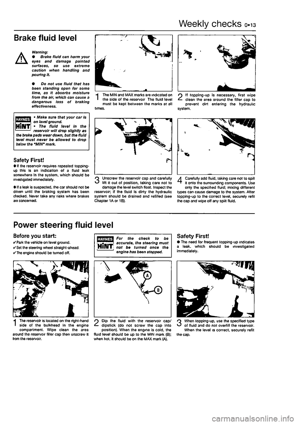
The MIN and MAX marks are indicated on the side of Ihe reservoir The fluid level must be kept between the marks at all times.
2
11 topping-up is necessary, first wipe clean the area around the filler cap to prevent dirt entering the hydraulic system.
the brake pads wear down, but the fluid level must never be allowed to drop below the "MIN" mark.
Safety First! • If the reservoir requires repeated topping* up this is an indication of a fluid leak somev/here In the system, which should be investigated immediately.
• If a leak is suspected, the car should not be driven until the braking system has been checked. Never take any risks where brakes are concerned.
Unscrew the reservoir cap and carefully lift it out of position, taking care not to damage the level switch float. Inspect the reservoir: if the fluid Is dirty Ihe hydraulic system should be drained and refilled (see Chapter 1A or 1B).
4
Carefully add fluid, taking care not to spill it onto the surrounding components, Use only the specified fluid; mixing different types can cause damage to the system. After topping-up to the correct level, secureiy refit the cap and wipe off any spilt fluid.
Power steering fluid level
Before you start: •Park the vehicle on level ground. • Set the steering wheel straight-ahead. •
The
engine should be turned off.
I
The reservoir is located on the right-hand side of the bulkhead in the engine compartment. Wipe clean the area around the reservoir filler cap then unscrew It from the reservoir.
For the check to be accurate, the steering must HlHT; not be turned once the engine has been stopped.
2
Dip the fluid with the reservoir cap/ dipstick (do not screw the cap into position). When the engine is cold, the fluid level should be up to Ihe MIN mark (B): when hot. it should be on the MAX mark (A).
Safety First! • The need for frequent topping-up indicates a leak, which should be investigated immediately.
3
When topping-up, use the specified type of lluid and do noi overfill the reservoir. When the level is correct, securely refit the cap.
Page 18 of 225
Lubricants and fluids 0.17
Lubricants and fluids
Engine Petrol Multigrade engine oil, viscosity SAE15W/40, to API SG/CD or better (Duckhams QXR Premium Petrol Engine Oil, or Duckhams Hypergrade Petrol Engine Oil) Diesel Multigrade engine oil, viscosity SAE15W/40, to API SG/CD or better Duckhams QXR Premium Diesel Engine Oil, or Duckhams Hypergrade Diesel Engine Oil) Cooling system Ethylene glycol-based antifreeze and soft water (Duckhams Antifreeze & Summer Coolant) Manual gearbox Hypoid gear oil, viscosity SAE80W to API GL4 (Duckhams Hypoid Gear Oil SOW GL-4) Automatic transmission Dexron type II automatic transmission fluid (ATF) (Duckhams ATF Autotrans III) Braking system Hydraulic fluid to SAE J1703F or DOT 4 (Duckhams Universal Brake & Clutch Fluid) Power steering Dexron type II automatic transmission fluid (ATF) (Duckhams ATF Autotrans Hi)
Choosing your engine oil
Engines need oil. not only to lubricate moving parts and minimise wear, but also to maximise power output and to Improve fuel economy. By introducing a simplified and improved range of engine oils. Duckhams has taken away the confusion and made it easier for you lo choose the right oil for your engine.
HOW ENGINE OIL WORKS
• Beating friction Without oil. the moving surfaces inside your engine will rub together, heat up and melt, quickly causing the engine to seize. Engine oil creates a film which separates these moving parts, preventing wear and heat build-up.
• Cooling hot-spots Temperatures Inside the engine can exceed 1000°
C.
The engine oil circulates and acts as a coolant, transferring heat from the hot-spots to the sump.
• Cleaning the engine internally Good quality engine oils clean the Inside of your engine, collecting and dispersing combustion deposits and controlling them until they are trapped by the oil niter or flushed out at oil change.
OIL CARE - FOLLOW THE CODE To handle and dispose of used engine oil safety, always: • Avoid skin contact with used engine oil. Repeated or prolonged contact can be harmful. • Dispose of used oil and empty packs In a responsible manner In an authorised disposal site. tti Call 0800 663366 to find qIqq f £ the one nearest to you. Never tip oil down drains or onto the ground.
DUCKHAMS ENGINE OILS For the driver who demands a premium quality oil for complete reassurance, we recommend synthetic formula Duckhama QXR Premium Engine Oils. For the driver who requires a straight-forward quality engine oil, we recommend Duckhams Hypergrade Engine Ote.
For further information and advice, call the Duckhams UK Helpline on 0800 212988.
^SGCKHAMS
Page 30 of 225
Every 20 000 miles - petrol models ia-h
clearance within specification. For example, if the measured valve clearance was 1.27 mm too great, a shim thicker by this amount will be required. Conversely, if the clearance was 1.27 mm too small, a shim thinner by this amount will be required. 13 Shims have their thickness (mm) engraved on them; although the engraved side should be fitted so as not to be visible, wear still occurs and often obliterates the number. In this case, measuring their thickness with a metric micrometer is the only method to establish their thickness (see illustration). t4 In practice, if several shims have to be changed, they can often be interchanged, so avoiding the necessity of having to buy more new shims than is necessary. 15 If more than two or three valve clearances are found to be incorrect, it will be more convenient to remove the camshaft for easier removal of the shims. 16 Where no clearance can be measured, even with the thinnest available shim in position, the valve will have to be removed and the end of its stem ground off squarely. This will reduce its overall length by the minimum amount to provide a clearance. This job should be entrusted to your dealer as it is important to keep the end of the valve stem square. 17 On completion, refit the camshaft cover and gasket, air cleaner and duct, and spark plugs. 18 lower the vehicle to the ground.
16 Manifold mounting check
Refer
1O
Chapters 4A. 48 and 4D and check tne tightness of the nuts and bolts securing the inlet and exhaust manifolds.
17
Fuel
filter renewal I I
Warning: Before carrying out the !\ f°llow'n9 operation, refer to the precautions given In Safety firstI A
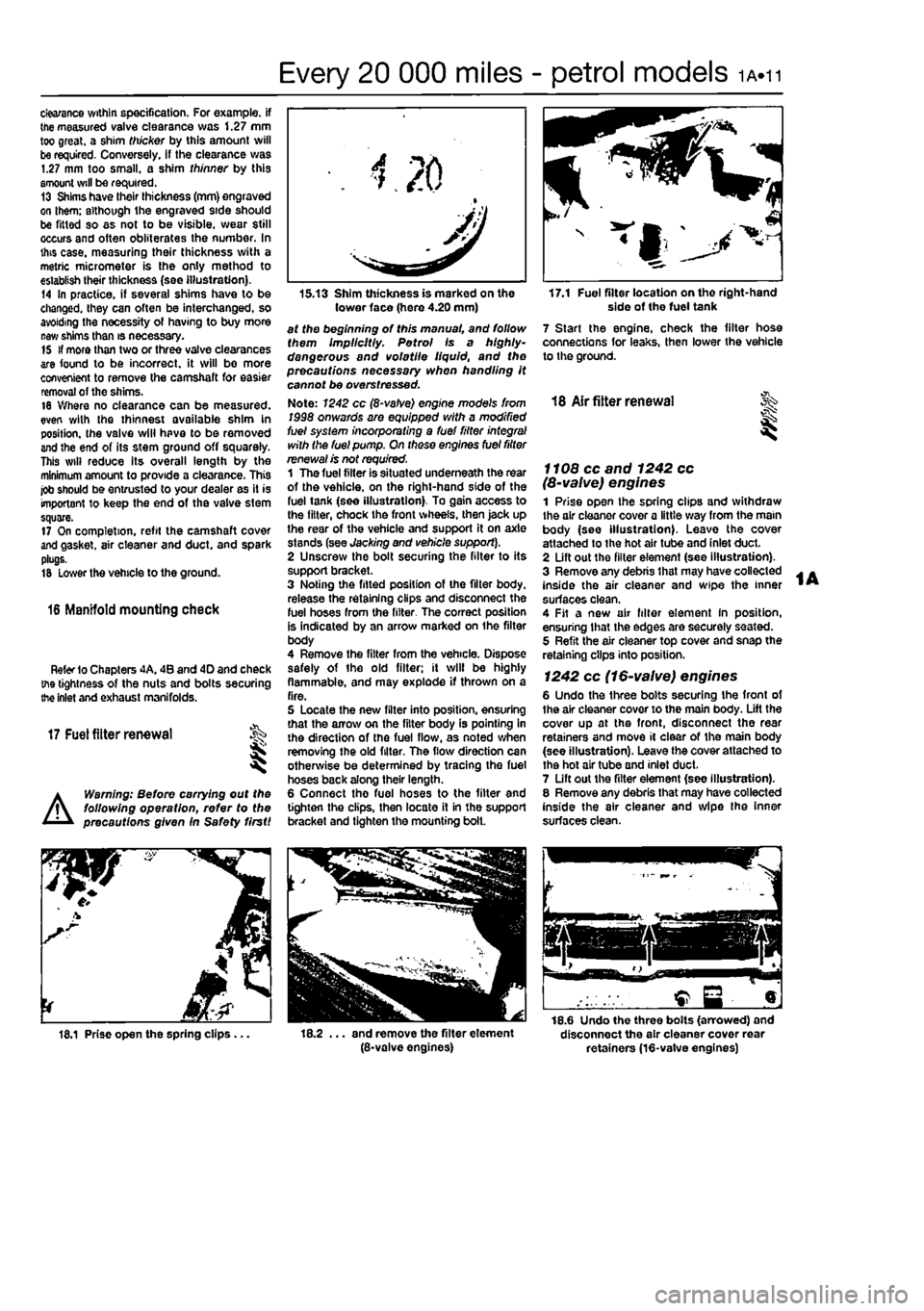
15.13 Shim thickness is marked on the tower face (here 4.20 mm) at the beginning of this manual, and follow them Implicitly. Petrol Is a highly-dangerous and volatile liquid, and the precautions necessary when handling it cannot be overstressed. Note: 1242 cc (8-vatve) engine mode's from 1998 onwards are equipped with a modified fuel system incorporating a fuel fitter integral with the fuel pump. On these engines fuel filter renewal is not required. 1 The fuel filter is situated underneath the rear of the vehicle, on the right-hand side of the fuel tank (see illustration). To gain access to the filter, chock the front wheels, then jack up the rear of the vehicle and support it on axle stands (see Jacking and vehicle support). 2 Unscrew the bolt securing the filter to its support bracket. 3 Noting the fitted position of the filter body, release the retaining clips and disconnect the fuel hoses from the filter. The correct position is indicated by an arrow marked on ihe filter body 4 Remove the filter from the vehicle. Dispose safely of the old filter; it will be highly flammable, and may explode if thrown on a fire. 5 Locate the new filter into position, ensuring that the arrow on the filter body is pointing in the direction of the fuel flow, as noted when removing the old filter. The flow direction can otherwise be determined by tracing the fuel hoses back along their length. 6 Connect the fuel hoses to the filter and lighten the clips, then locate it in the support bracket and tighten the mounting bolt.
17.1 Fuel filter location on tho right-hand side of the fuel tank 7 Start the engine, check the filter hose connections for leaks, then lower the vehicle to the ground.
18 Air fitter renewal
I
f f 08 cc and 1242 cc (8-valve) engines 1 Prise open the spring clips and withdraw the air cleaner cover a little way from the main body (see illustration). Leave the cover attached to the hot air tube and inlet duct. 2 Lift out the filter element (see illustration). 3 Remove any debris that may have collected inside the air cleaner and wipe the inner surfaces clean. 4 Fit a new air filter element In position, ensuring that the edges are securely seated. 5 Refit the air cleaner top cover and snap the retaining clips into position.
1242 cc (16-valve) engines 6 Undo the three bolts securing the front of Ihe air cleaner cover to the main body. Lift the cover up at the front, disconnect the rear retainers and move it clear of the main body {see illustration). Leave the cover attached to the hot air tube and inlet duct. 7 Lift out the filter element (see illustration). 8 Remove any debris that may have collected inside the air cleaner and wipe the inner surfaces clean.
18.1 Prise open the spring clips... . and remove the filter element (8-valve engines)
18.6 Undo the three bolts (arrowed) and disconnect the air cleaner cover rear retainers (16-vatve engines)
Page 31 of 225
1A.12
Every 20 000 miles - petrol models
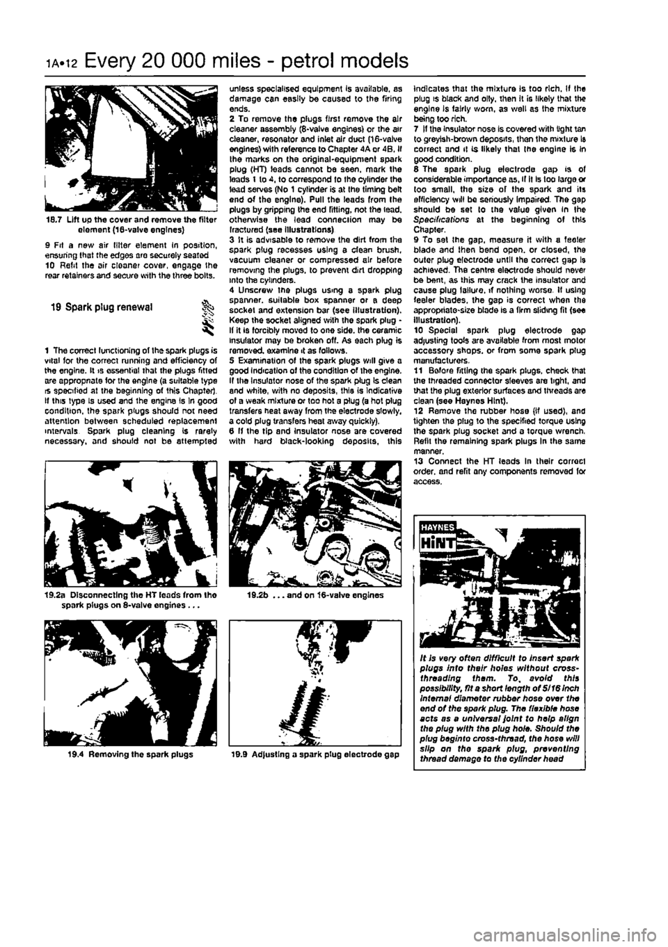
18.7 Lift up the cover and remove the filter element (18-va!ve engines) 9 Fit a new air (liter element In position, ensuring that the edges are securely seated 10 Refit the air cloaner cover, engage the rear retainers and secure with the three bolts.
19 Spark plug renewal
1 The correct functioning of the spark plugs is vital for the correct running and efficiency of the engine. It is essential that the plugs fitted are appropnate for the engine (a suitable type is specified at the beginning of this Chapter. If this type is used and the engine Is In good condition, the spark plugs should not need attention between scheduled replacement intervals Spark plug cleaning Is rarely necessary, and should not be attempted
19.2a Disconnecting tho HT leads from Iho spark plugs on 8-valve engines ...
19.4 Removing the spark plugs
unless specialised equipment Is available, as damage can easily be caused to the firing ends. 2 To remove the plugs first remove the air cleaner assembly (8-vaive engines) or the a»r cleaner, resonator and inlet air duct (16-valve engines) with reference to Chapter 4A or 4B. if the marks on the original-equipment spark plug (HT) leads cannot be seen, mark the leads 1 to 4, to correspond to the cylinder the lead serves (No 1 cylinder is at the timing belt end of the engine). Pull the leads from the plugs by gripping the end fitting, not the lead, otherwise the lead conneciion may be Iractured (see illustrations) 3 It is advisable to remove the dirt from the spark plug recesses using a clean brush, vacuum cleaner or compressed air before removing the plugs, to prevent dirt dropping into the cylinders. 4 Unscrew the plugs using a spark plug spanner, suitable box spanner or a deep socket and extension bar (see illustration). Keep the socket aligned with the spark plug • If it is forcibly moved to one side, the ceramic insulator may be broken off. As each plug is removed examine 4 as fallows. 5 Examination of the spark plugs will give a good Indication of the condition of the engine. If the Insulator nose of the spark plug Is clean and white, with no deposits, this is Indicative of a weak mixture or too hot a plug (a hot plug transfers heal away from the electrode slowly, a cold plug transfers heat away quickly). 6 If the tip and insulator nose are covered with hard black-looking deposits, this
19.2b ... and on 16-valve engines
19.9 Ad|ustlng a spark plug electrode gap
indicates that the mixture Is too rich. If the plug is black and oily, then It is likely that the engine is fairly worn, as well as the mixture being too rich. 7 If the Insulator nose is covered with light tan to greyish-brown deposits, then the mixture Is correct and it is likely that (he engine Is in good condition. 6 The spark plug electrode gap is of considerable importance as, if it Is too large or too small, the size of the spark and its efficiency will be seriously impaired. The gap should be set to the value given in the Specifications at the beginning of this Chapter. 9 To set the gap. measure it with a feeler blade and then bend open, or closed, the outer plug elect/ode until the correct gap l9 achieved. The centre electrode should never be bent, as this may crack the insulator and cause plug I allure, if nothing worse. If using feeler blades, the gap is correct when the appropriate-size blade is a firm sliding fit (see illustration). 10 Special spark plug electrode gap adjusting tools are available from most motor accessory shops, or from some spark plug manufacturers, 11 Before fitting the spark plugs, check that the threaded connector sleeves are tight, and that the plug exterior surfaces and threads are clean (see Haynes Hint). 12 Remove the rubber hose (If used), and tighten the plug to the specified torque using the spark plug socket and a torque wrench, Refit the remaining spark plugs In the same manner. 13 Connect the HT leads In their correct order, and refit any components removed for access.
It is very often difficult to insert spark plugs into their holes without cross-threading them. To, avoid this possibility, fit a short length of Si 16 Inch Internal diameter rubber hose over the end of the spark plug. The flexible hose acts as a universal Joint to help align the plug with the plug hole. Should the plug beginto cross-thread, the hose will slip on the spark plug, preventing thread damage to the cylinder head
Page 45 of 225
Every 10 000 miles - diesel models ib«9
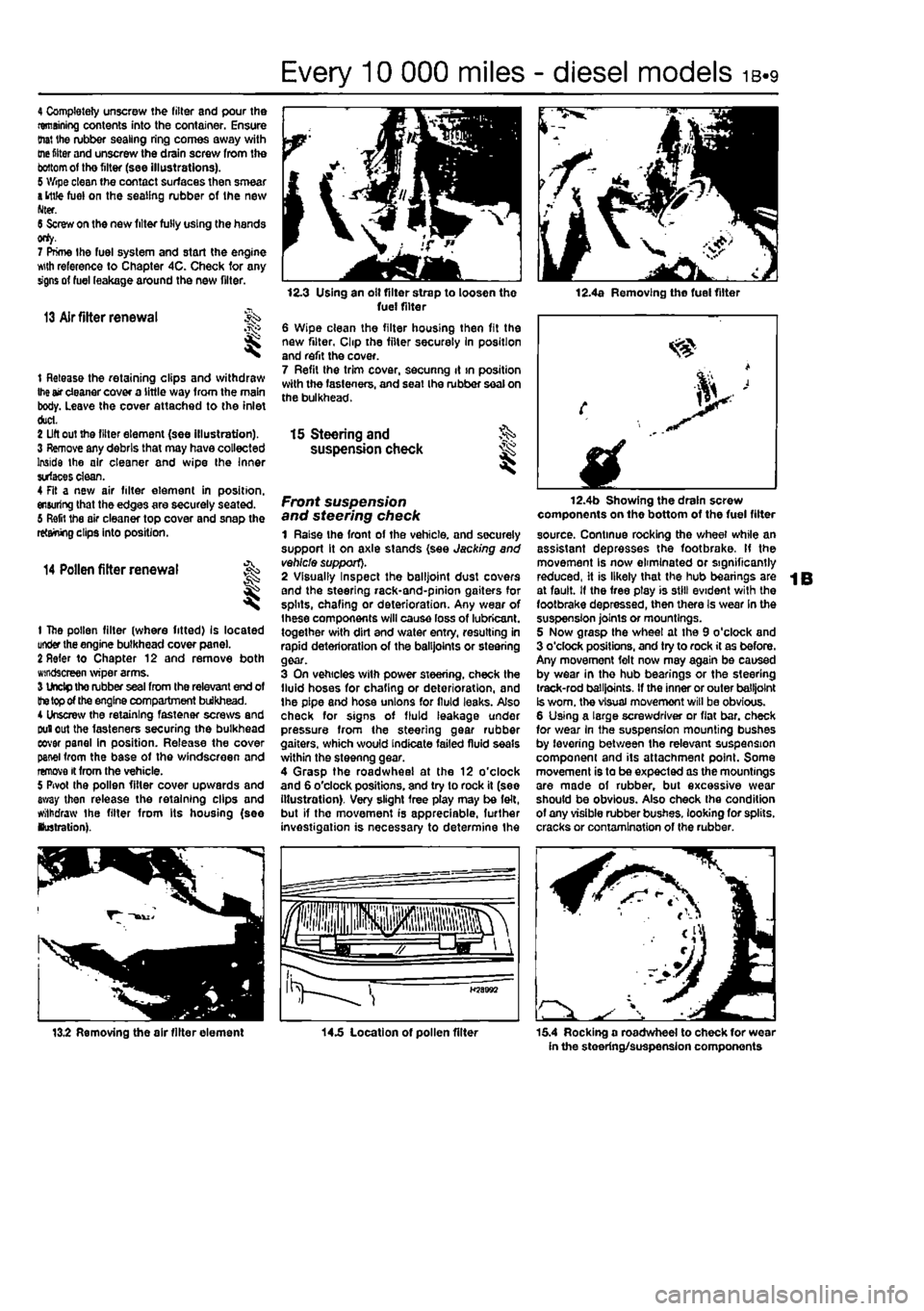
4 Completely unscrew the filter and pour the remaining contents into the container. Ensure (hat the rubber sealing ring comes away with
me
fitter and unscrew the drain screw from the
bottom
of tho filter (see illustrations). 5 Wipe clean the contact surfaces then smear
a
ittfe fuel on the sealing rubber of the new Nter. 6 Screw on the new filter fully using the hands orty. 7 Prime the fuel system and start the engine wth reference to Chapter 4C. Check for any signs of fuel leakage around the new filter.
13 Air fitter renewal
t Release the retaining clips and withdraw
Ihe
air cleaner cover a little way from the main body. Leave the cover attached to the inlet duct. 2 Lift out the filter element (see illustration). 3 Remove any debris that may have collected Inside the air cleaner and wipe the Inner surfaces clean. 4 Fit a new air filter element in position, ensuring that the edges are securely seated. 6 Refit the air cleaner top cover and snap the retaining clips into position.
14 Pollen filter renewal
t
1 The pollen filter (where fitted) Is located under the engine bulkhead cover pane). 2 Refer to Chapter 12 and remove both windscreen wiper arms. 3 Undp tho rubber seal from the relevant end of
the top
of the engine compartment bulkhead. 4 Unscrew the retaining fastener screws and Duiout the fasteners securing the bulkhead eovar panel in position. Release the cover panel from the base of the windscreen and remove it from the vehicle. 5 Pivot the pollen filter cover upwards and away then release the retaining clips and withdraw the filter from Its housing (see lustration).
12.3 Using an olt filter strap to loosen the fuel filter 6 Wipe clean the filter housing then fit the new filter, Clip the filter securely In position and refit the cover. 7 Refit the trim cover, secunng it >n position with the fasteners, and seat Ihe rubber seal on the bulkhead.
12.4a Removing the fuel filter
15 Steering and §S> suspension check ^
Front suspension and steering check 1 Raise the front of the vehicle, and securely support it on axle stands (see Jacking and vehicle support). 2 Visually Inspect the balljoint dust covers and the steering rack-and-pinion gaiters for splits, chafing or deterioration. Any wear of Ihese components will cause loss of lubricant, together with dirt and water entry, resulting in rapid deterioration of the balljoints or steering gear. 3 On vehicles with power steering, check the fluid hoses for chafing or deterioration, and the pipe and hose unions for fluid leaks. Also check for signs of fluid leakage under pressure from the steering gear rubber gaiters, which would indicate failed fluid seals within the steenng gear. 4 Grasp the roadwheel at the 12 o'clock and 6 o'clock positions, and try to rock it (see illustration). Very slight free play may be felt, but if the movement is appreciable, further investigation is necessary to determine the
fplllll iHpjiiisisps fa^aJw a LJgr >
H58B92
12.4b Showing the drain screw components on the bottom of the fuel filter source. Continue rocking the wheel while an assistant depresses the footbrake. If the movement Is now eliminated or significantly reduced, it is likely that the hub bearings are at fault. If the free ptay is still evident with the footbrake depressed, then there Is wear In the suspension joints or mountings. 5 Now grasp the wheel at the 9 o'clock and 3 o'clock positions, and try to rock it as before. Any movement felt now may again be caused by wear in the hub bearings or the steering track-rod balljoints. If the inner or outer balljoint Is worn, the visual movemont will be obvious. 6 Using a large screwdriver or flat bar. check for wear in the suspension mounting bushes by levering between the relevant suspension component and its attachment point. Some movement is to be expected as the mountings are made of rubber, but excessive wear should be obvious. Also check the condition of any visible rubber bushes, looking for splits, cracks or contamination of the rubber.
13.2 Removing the air filter element 14.5 Location of pollen filter 15.4 Rocking a roadwheel to check for wear in the steering/suspension components
Page 56 of 225
2A*10 SOHC (8-valve) petrol engine in-car repair procedures
6.3 Camshaft cover gasket
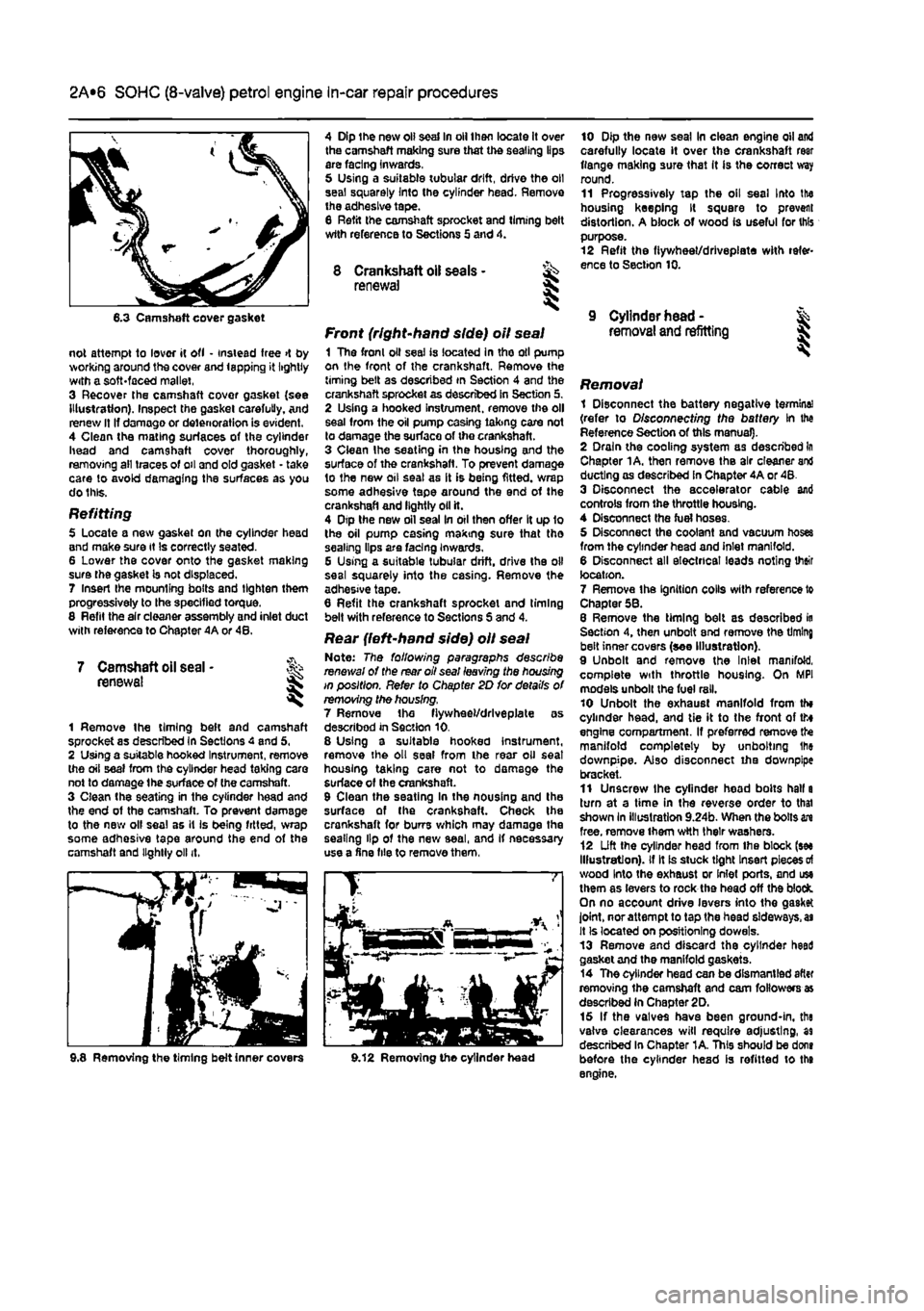
not attempt to lover it ofl • instead free >t by working around the cover and lapping it lightly with a soft-faced mallet, 3 Recover the camshaft covor gasket {see Illustration). Inspect the gasket carefully. And renew It If damage or deterioration is evident. 4 Clean the mating surfaces of the cylinder head and camshaft cover thoroughly, removing all traces of oil and old gasket - take care to avoid damaging the surfaces as you do this.
Refitting 5 Locate a new gasket on the cylinder head and make sure it Is correctly seated. 6 Lower the cover onto the gasket making sure the gasket is not displaced. 7 Insert Ihe mounting bolts and tighten them progressively to the specified torque. 8 Refit the air cleaner assembly and inlet duct with reference to Chapter 4A or 48.
7 Camshaft oil seal • renewal I
1 Remove the timing beft and camshaft sprocket as described in Sections 4 and 5, 2 Using a suitable hooked Instrument, remove the oil seal from the cylinder head taking care not to damage the surface of (he camshaft. 3 Clean the seating in the cylinder head and the end of the camshaft. To prevent damage to the new olf seal as it is being fitted, wrap some adhesive tape around the end of the camshaft and lightly oil it.
4 Dip the new oil seal In oil then locate it over the camshaft making sure that the sealing lips are facing inwards, 5 Using a suitable tubular drift, drive the oil seal squarely Into the cylinder head. Remove the adhesive tape. 8 Refit the camshaft sprocket and liming belt wtth reference to Sections 5 and 4.
8 Crankshaft oil seals - ^ renewal S
Front (right-hand side) oil seal 1 The fronl oil seal is located in tho oil pump on the front of the crankshaft. Remove the timing belt as described in Section 4 and the crankshaft sprocket as described in Section 5. 2 Using a hooked instrument, remove the oil seal from the oil pump casing taking care not to damage the surface of the crankshaft. 3 Clean Ihe seating in the housing and the surface of the crankshaft. To prevent damage to the new oil seal as it is being fitted, wrap some adhesive tape around the end of the crankshaft and lightly oil it. 4 Dtp the new oil seal In oil then offer It up 1o the oil pump casing making sure that tho sealing lips are facing Inwards. G Using a suitable tubular drift, drive the oil seal squarely into the casing. Remove the adhesive tape. 6 Refit the crankshaft sprocket and timing belt with reference to Sections S and 4.
Rear {left-hand side) oil seal Note: The following paragraphs describe renewal of the rear oil seal leaving the housing in position. Refer to Chapter 2D for details of removing the housing. 7 Remove the fiywheel/drlveplate as described in Section 10. 8 Using a suitable hooked instrument, remove the oil seal from the rear oil seat housing taking care not to damage the surface of Ihe crankshaft. 9 Clean the seating In the nousing and the surface of the crankshaft. Check the crankshaft for burrs which may damage the sealing lip of the new seal, and If necessary use a fine file to remove them,
10 Dip the new seal In clean engine oil and carefully locate it over the crankshaft rear flange making sure that It is the correct way round. 11 Progressively tap the oil seal Into the housing keeping It square to prevent distortion. A block of wood is useful for this purpose. 12 Refit the fiywheet/drlvepiate with refer-ence to Section 10.
9 Cylinder head -removal and refitting I
i Removing the timing belt inner covers 9.12 Removing the cylinder head
Removal 1 Disconnect the battery negative termine! (refer to Disconnecting the battery In the Reference Section of this manual). 2 Drain the cooling system as described In Chapter 1A. then remove the air cleaner and ducting as described in Chapter 4A or 48. 3 Disconnect the accelerator cable and controls from the throttle housing. 4 Disconnect the fuel hoses. 5 Disconnect the coolant and vacuum hoses from the cylinder head and inlet manifold. 6 Disconnect all electrical leads noting their location. 7 Remove the Ignition colls with reference to Chapter 58. 8 Remove the timing belt as described in Section 4, then unbolt end remove the timing belt inner covers (see Illustration). 9 Unbolt and remove the Inlet manifold, complete with throttle housing. On MPI models unbolt the fuel rail. 10 Unbolt the exhaust manifold from th» cylinder head, and tie it to the front of tto engine compartment. If preferred remove the manifold completely by unbolting Ihe downpipe. Also disconnect iha downpipe bracket. 11 Unscrew the cylinder head bolts hall a turn at a time in the reverse order to thai shown In illustration 9.24b. When the bolts in free, remove them wtth their washers. 12 Lift the cylinder head from Ihe block (see Illustration), if It is stuck tight Insert pieces
of
wood Into the exhaust or Inlet ports, and use them as levers to rock the head off the block. On no account drive levers into the gasket joint, nor attempt to tap the head sideways,
as
It Is located on positioning dowels. 13 Remove and discard the cylinder heed gasket and the manifold gaskets. 14 The cylinder head can be dismantled after removing the camshaft and cam followers as described in Chapter 2D. 15 If the valves have been ground-in, the valve clearances will require adjusting, as described In Chapter 1A. This should be dons before the cylinder head is refitted to the engine.
Page 68 of 225
2B*8 DOHC (16-valve) petrol engine in-car repair procedures
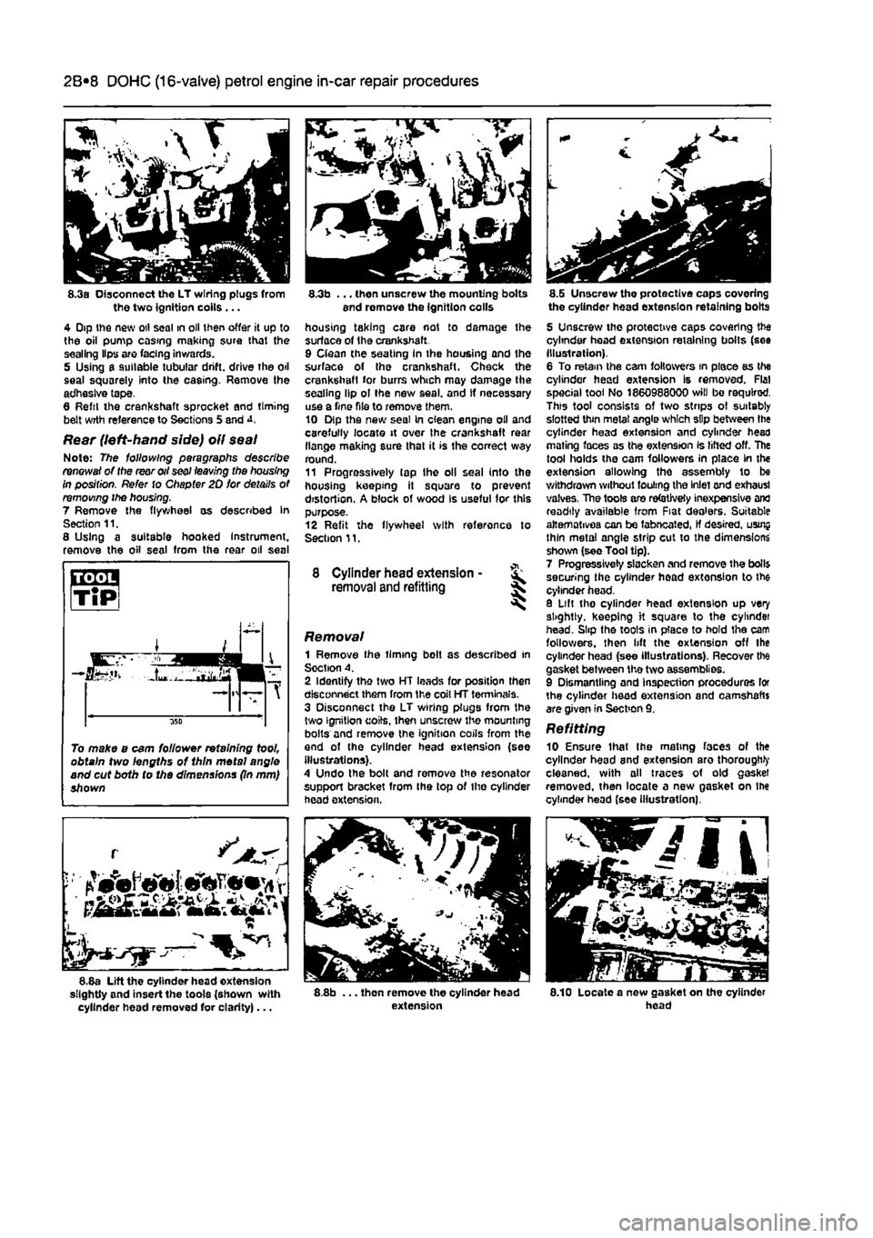
8.3a Disconnect the LT wiring plugs from the two Ignition coils ... 4 Dip the new oil seal in oil then offer it up to the oil pump casing making sure that the sealing Hps are facing inwards. 5 Using a suitable tubular drift, drive the oil seal squarely into the casing. Remove the adhesive tape, 8 Reftl the crankshaft sprocket and timing belt wrth reference to Sections 5 and
Rear (left-hand side) oil seal Note: The following paragraphs describe renewal of the rear oil seal leaving the housing in position. Refer to Chapter 20 for details of removing ihe housing. 7 Remove the flywheel as described In Section 11. 8 Using a suitable hooked Instrument, remove the oil seal from the rear oil seal
L •
~ 1 8.8a Lift the cylinder head extension slightly and insert the tools {shown with cylinder head removed for clarity)...
8.3b ... then unscrew the mounting bolts end romove the ignition colls housing taking care not to damage the surface of the crankshaft. 9 Clean the seating In the housing and the surface of Ihe crankshaft. Check the crankshaft for burrs which may damage the sealing lip ol Ihe new seal, and If necessary use a Tine file to remove them. 10 Dip the new seal In clean engine oil and carefully locate it over Ihe crankshaft rear flange making sure that it is the correct way round. 11 Progressively tap the oil seal into the housing keeping it square to prevent distortion. A block of wood Is useful for this purpose. 12 Refit the flywheel with reference to Section 11,
8 Cylinder head extension -removal and refitting ^
Removal 1 Remove the timing bolt as described in Soction A. 2 Identify the two HT leads for position then disconnect them from the coil HT terminals. 3 Disconnect the LT wiring plugs from the two ignition coils, then unscrew the mounting bolts and remove the ignition coils from the and of the cylinder head extension {see illustrations). A Undo the bolt and remove the resonator support bracket from Ihe top of the cylinder head extension,
8.8b ... thon remove the cylinder head extension
8.G Unscrew tho protective caps covering the cylinder head extension retaining bolts
5 Unscrew the protective caps covering the cylinder head extension retaining bolts (see Illustration). 6 To retain the cam followers in place as the cylinder head extension Is removed. Flat special tool No 1860988000 will bo required. This tool consists of two strips ol suitably slotted thin metal angle which sDp between the cylinder head extension and cylinder head mating faces as the extension Is lifted off. The tool holds the cam followers in place in the extension allowing the assembly to be withdrawn without fouling the Inlet and exhausl valves, The tools are refetJvety inexpensive and readily available from Fiat dealers. Suitable alternatives can be fabneated, If desired, usrnj thin metal angle strip cut to the dimensions shown (see Tool tip). 7 Progressively slacken and remove the boll$ securing the cylinder head extension to the cylinder head. 8 Lilt tho cylinder head extension up very slightly, keeping it square to the cylindei head. Slip the toots in place to hold the cam followers, then lift the extension off the cylinder head (see illustrations). Recover the gasket between the two assemblies. 9 Dismantling and Inspection procedures lor the cylinder head extension and camshafts are given in Section 9. Refitting 10 Ensure thai Ihe mating faces of the cylinder head and extension aro thorough^ cleaned, with all traces of old gasket removed, then locate a new gasket on Ihe cylinder head (see Illustration).
8.10 Locate a new gasket on the cylinder head
To make a cam follower retaining tool, obtain two lengths of 1hln metal angle and cut both to the dimensions (In mm) shown
Page 80 of 225
2C*2 Diesel engine in-car repair procedures
Refitting 6 Locate a new gasket on the cylinder head and make sure tt Is correctly seated. 7 Lower the cover onto the gasket making sure the gasket Is not displaced, 8 Insert the mounting bolts and tighten them securely In a progressive sequence. Position Ihe support brackets as noted during removal. 9 Clip ihe coolant hoses in position then refil the air ducting.
7 Camshaft oil seal -renewal
8 Crankshaft oil seals -renswal I
9 Cylinder head -
removal
and refitting
1 Remove the timing belt and camshaft sprocket as descnbed in Sections 4 and 5. 2 Using a suitable hooked instrument, remove tho oil seal from the cylinder head taking care nol to damage the surface of the camshafl. Alternatively drill a small hole In tho oil seal and Insert a self-topping screw - the seal can then be removed by pulling on the screw with a pair of pliers. 3 Clean the seating In the cylinder head and tho end of the camshaft To prevent damage to the new oil seal as It is being fitted, wrap some adhesive tape around the end ol the camshaft and lightJy oil it. 4 Dip tho new ail s«al In oil then locate it over Ihe camshaft making sure that the sealing lips are facing inwards. 5 Using a suitable tubular drift, drive the oil seal squarely into the cylinder h*ad. Remove the adhesive tap© 6 Refit the camshaft sprocket and timing belt with reference to Sections 6 and 4.
Front (right-hand side) oil seal t The front oil seal is located in the oil pump casing on the front of the crankshaft. Remove the timing belt as described in Section 4 and the crankshaft sprocket as described in Section 5, 2 Using a suitable hooked instrument, remove the oil seal from the oil pump casing taking care not to damage the surface of the crankshaft. Alternatively drill a small hole In the oil soal and insert a self-tapping screw - the seal can then be removed by pulling on the screw with a pair of pliers. 3 Clean the seating in the oH pump and the surface of the crankshaft. To prevent damage to the new off seal as It Is being fitted, wrap some adhesive tape around the end of tha crankshaft and lightly oil it. 4 Oip the new oii seal In oil then otter it up to the oil pump casing making sure that the sealing Hps are facing inwards,
8.Ba Rear oil soal and housing
5 Using a suitable tubular drift, driva the oil sea! squarely into the casing. Remove the adhesive tape. 6 Refit the crankshaft sprocket and timing belt with reference to Sections 5 and 4.
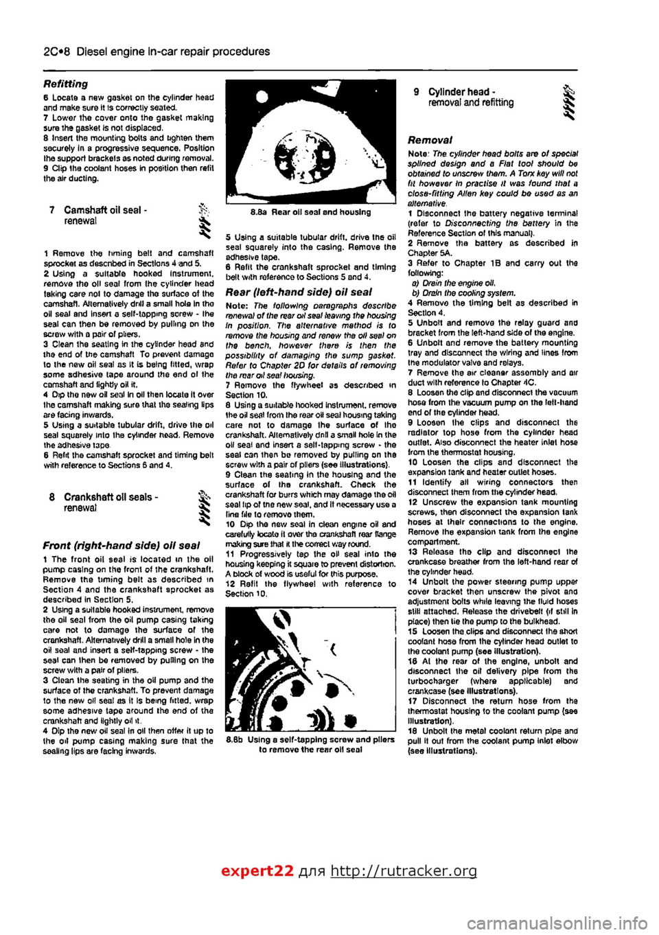
Rear (left-hand side) oil seal Note: The following paragraphs describe renewal of the rear oil seal leaving the housing In position. The alternative mathod is to remove the housing and renew the oil seel on the bench, however there is then the possibility of damaging the sump gasket. Refer to Chapter 2D for details of removing the mar oil sea! housing. 7 Ramove the flywheel as described in Section 10. 8 Using a suitable hooked Instrument. remove 1he oil seat from the roar oil seal housing taking care not to damage Ihe surface of Ihe crankshaft. Alternatively dnll a small hole In the o» seal and insert a self-tapping screw - the seal can ihan be removed by pulling on the screw with a pair of pliers (see Illustrations), 9 Clean the seating in the housing and the surface of the crankshaft. Check the crankshaft for burrs which may damage the oil seal tip of tno new saal, and It necessary use a Una file to removothem. 10 Dip the new soal in clean engine oil and carefully tocato it over tho crankshafl rear Range making sure that
H
the correct way round. 11 Progressively tap the oH seal into the housing keepfng it square to prevent distortion. A block of wood is useful for this purpose. 12 Refit the flywheel with reference to Section 10.
I
5.8b Using a self-tapping screw and pliers to remove the rear oil seal
Removal Note: The cylinder head bolts are of special splined design and a Fiat tool should be obtained to unscrew them. A Torn key will
not
fit however In practise It was found that a close-fitting Allen key could bo used as an alternative. 1 Disconnect the battery negative terminal (refer to Disconnecting the battery in the Reference Section of this manual), 2 Remove tha battery as described In Chapter 5A. 3 Refer to Chapter IB and carry out the following: o) Drain the engine oil, b) Drain the cooling system. 4 Remove the timing belt as described in Section 4. 5 Unbolt and remova the relay guard and bracket from the left-hand side of the engine. 6 Unbolt and remove the battery mounting tray and disconnect the wiring and lines from the modulator valva and relays. 7 Remove the air eleanar assembly and air duct with reference lo Chapter 4C. 8 Loosen the clip and disconnect the vacuum hosa from the vacuum pump on the left-hand end of the cylinder head. 9 Loosen Ihe clips and disconnect the radiator top hose from the cylinder head outlet. Also disconnect the heater inlet hose from the thermostat housing, 10 Loosen the clips and disconnect the expansion tank and heater outlet hoses. 11 Identify all wiring connectors then disconnect them from the cylinder head, 12 Unscrew the expansion tank mounting screws, then disconnect tha expansion tank hoses at their connections to the engine. Remove the expansion tank from tha engine compartment. 13 Release tha clip and disconnect ihe crankcase breather from the left-hand rear of the cylinder head. 14 Unbolt the power steering pump uppar cover bracket then unscrew the pivot ana adjustment bolts while leaving ihe tMd lioses still attached. Release the drivebelt (if still In place) then tie the pump to the bulkhead. 15 Loosen tha clips and disconnect Ihe short coolant hose from the cylinder head outlet to the coolant pump (soe illustration). 18 At the rear of the engine, unbolt and disconnect the oil delivery pipe from the turbocharger (where applicable) and crankcase (see Illustrations). 17 Disconnect the return hose from tha thermostat housing to the coolant pump (see Illustration), 18 Unbolt the metal coolant return pipe and pull it out from the coolant pump inlet elbow (see Illustrations).
expert22 flna http://rutracker.org
Page 105 of 225
2D*10 Engine removal and overhaul procedures
7.13 Positioning of piston rings (petrol engine) 11 Scrape away all traces of carbon from the top of the piston. A hand-held wire brush (or a piece of fine emery cloth) can be used, once the majority ot the deposits have been scraped away. 12 Remove the carbon from the ring grooves In the piston, using an old ring. Break the ring in half to do this (be careful not to cut your fingers - piston rings are sharp). Be careful to remove only the carbon deposits • do not remove any metal, end do not nick or scratch the sides of the ring grooves. 13 Once the deposits have been removed, clean the piston/connecting rod assembly with paraffin or o suitable solvent, and dry thoroughly. Make sure that the oil return holes In the ring grooves are clear. Fit the rings to their respective grooves meking sure they are positioned the correct way round where applicable (see illustration). 14 If the pistons and cylinder bores are not
7.22 Prising out the gudgeon pin retaining circilps damagea or worn excessively, and if the cylinder block does not need to be rebored. the original pistons can be refitted. Normal piston wear shows up as even vertical wear on the piston thrust surfaces, and slight looseness of the top ring In its groove. New piston rings should always be used when the engine is reassembled. 15 Carefully inspect each piston for cracks around the skirt, around the gudgeon pin holes, and at the piston nng lands (between the ring grooves). 16 Look for scoring and scuffing on the ptston skirt, holes in the piston crown, and burned areas at the edge of the crown. If the skirt is scored or scuffed, the engine may have been suffering from overheating, end/or abnormal combustion which caused excessively high operating temperatures. The cooling and lubrication systems should be checked thoroughly. Scorch marks on the sides of the pistons show that blow-by has occurred. A hole in the piston crown, or burned areas at the edge of the piston crown, Indicates that abnormal combustion has been occurring. If any of the above problems exist, the causes must be investigated and corrected, or the
7.26a Piston to connecting rod assembly (petrol engine) 1 Piston grade (A) end directional arrow on piston crown (towards timing belt end) 2 Connecting rod/cap matching numbers 3 Gudgeon pin offset in piston (0.9 to 1.1 mm) Arrow indicates direction of crankshaft rotation
7.26b Piston to connecting rod assembly (diesel engine) 1 Piston crown
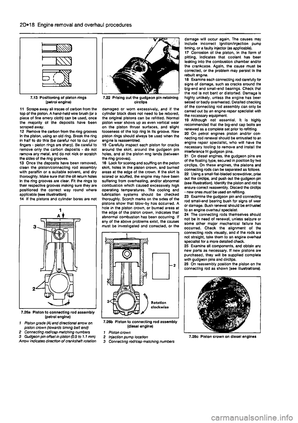
damage will occur again. The causes may Include Incorrect Ignition/injection pump timing, or a faulty injector (as applicable). 17 Corrosion of the piston, in the form ol pitting, indicates that coolant has been leaking into the combustion chamber and/or the crankcase. Again, the cause must be corrected, or the problem may persist In the rebuilt engine. 16 Examine each connecting rod carefully for signs of damage, such as cracks around the big-end and small-end bearings. Check that the rod is not bent or distorted, Damage is highly unlikely, unless the engine has been seized or badly overheated. Detailed checking of the connecting rod assembly can only be earned out by an engine repair specialist with the necessary equipment. 19 Although not essential. It is highly recommended that the big-end cap bolts are renewed as a complete set prior lo refitting. 20 On petrol engines piston and/or con-necting rod renewal should be entrusted to an engine repair specialist, who will have the necessary tooling to remove and install the interference fit gudgeon pins. 21 On diesel engines, the gudgeon pins are of the floating type, secured in position by two circlips. On these engines, the pistons and connecting rods can be separated as follows. 22 Using a small fiat-bladed screwdriver, prise out ihe circlips, and push out the gudgeon pin (see illustration). Identify the piston and rod to ensure correct reassembly. Discard the circlips - new ones must be used on refitting. 23 Examine the gudgeon pin and connecting rod small-end bearing bush for signs of wear or damage. Bush renewal should be entrusted to an engine overhaul specialist. 24 The connecting rods themselves should not be In need of renewal, unless seizure or some other major mechanical failure has occurred. Check the alignment of the connecting rods visually, and if the rods are not straight, take ihem to an engine overhaul specialist for a more detailed check. 25 Examine all components, and obtain any new parts as necessary. If new pistons are purchased, they will be supplied complete with gudgeon pins and circlips. 26 On reassembly position the piston on the connecting rod as shown (see Illustrations),
Injection pump location Connecting rod/cap matching numbers 7.28c Piston crown on diesel engines