Eated FIAT PUNTO 1998 176 / 1.G User Guide
[x] Cancel search | Manufacturer: FIAT, Model Year: 1998, Model line: PUNTO, Model: FIAT PUNTO 1998 176 / 1.GPages: 225, PDF Size: 18.54 MB
Page 110 of 225
2D*10 Engine removal and overhaul procedures
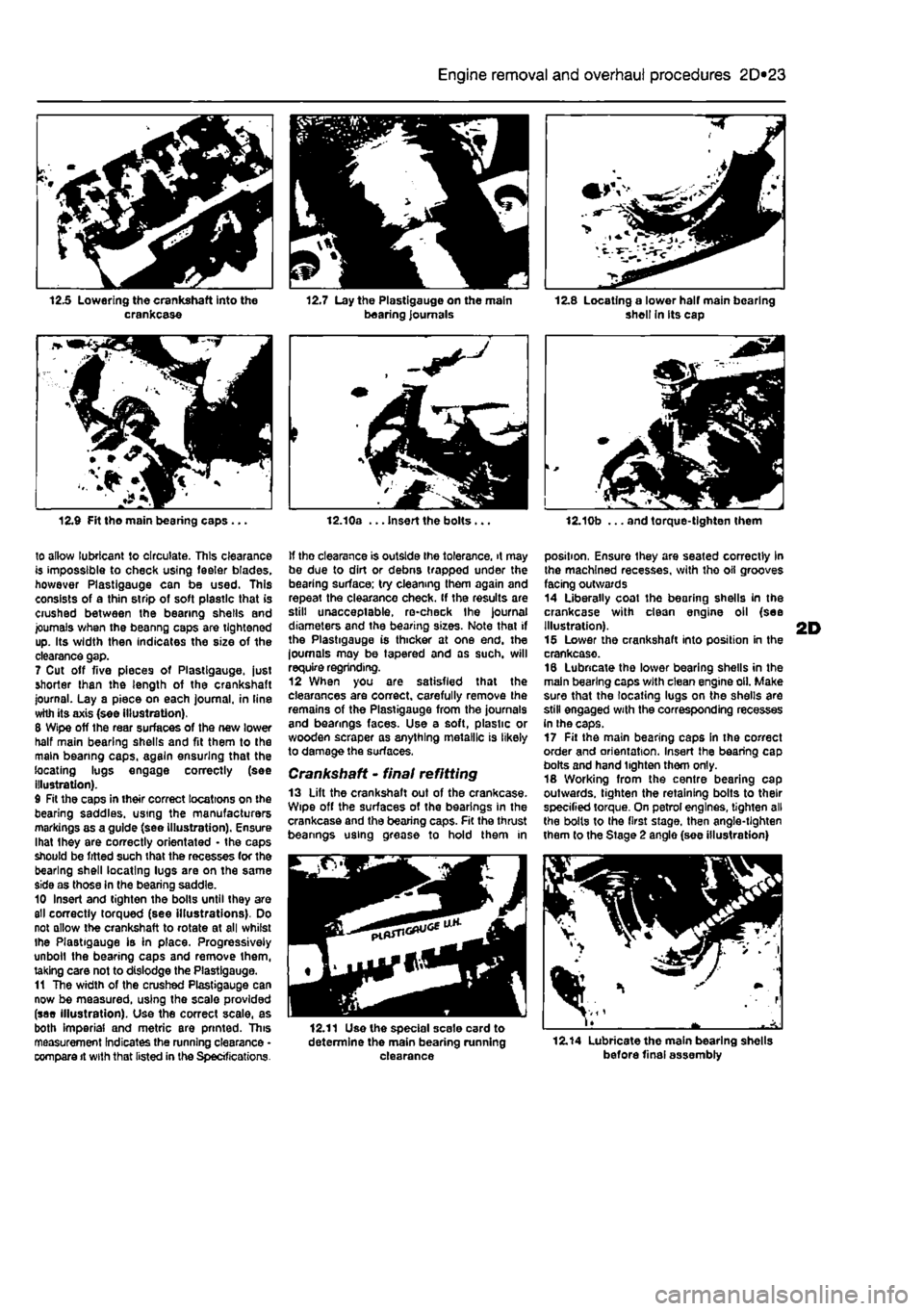
12.5 Lowering the crankshaft into the crankcase
12.9 Fit tho main bearing caps...
to allow lubricant to circulate. This clearance is impossible to check using feeler blades, however Plastlgauge can be used. This consists of a thin strip of soft plastic that is crushed between the bearing shells and journals when the beanng caps are tightened up. Its width then indicates the size of the clearance gap. 7 Cut off five pieces of Plastlgauge. just shorter than the length of the crankshaft journal. Lay a piece on each journal, in line with its axis (see Illustration). 8 Wipe off the rear surfaces of the new lower half main bearing shells and fit them to the main beanng caps, again ensuring that the locating lugs engage correctly (see illustration). 9 Fit the caps in their correct locations on the bearing saddles, using the manufacturers markings as a guide (see illustration). Ensure lhat Ihey are correctly orientated • the caps should be fitted such that the recesses (or the bearing shell locating lugs are on the same side as those in the bearing saddle. 10 Insert and tighten the bolls until they are
811
correctly torqued (see illustrations). Do not allow the crankshaft to rotate at all whilst ihe Plastlgauge is in place. Progressively unbolt the bearing caps and remove them, taking care not to dislodge the Plastlgauge. 11 The width of the crushed Plastigauge can now be measured, using the scale provided (see illustration). Use the correct scale, as both Imperial and metric are printed. This measurement Indicates the running clearance • compare it with that listed in the Specifications.
21 \ „ 12.7 Lay the Plastigauge on the main bearing journals
t
12.10a ... Insert the bolts...
If tho clearance is outside ihe tolerance, it may be due to dirt or debns trapped under the bearing surface; try cleaning them again and repeat the clearance check. If the results are still unacceptable, re-check Ihe journal diameters and the bearing sizes. Note that if the Plastigauge is thicker at one end. the loumals may be tapered and as such, will require regrinding. 12 When you are satisfied that the clearances are correct, carefully remove the remains of the Plastigauge from the journals and bearings faces. Use a soft, plastic or wooden scraper as anything metallic is likely to damage the surfaces.
Crankshaft • final refitting 13 Lift the crankshaft out of the crankcase. Wipe off the surfaces of the bearings in the crankcase and the bearing caps. Fit the thrust beanngs using grease to hold them in
12.11 Use the special scale card to determine the main bearing running clearance
shell In its cap
12.10b ... and torque-tighten them
position, Ensure they are seated correctly in the machined recesses, with tho oil grooves facing outwards 14 Liberally coat the bearing shells in the crankcase with dean engine oil (see Illustration). 15 Lower the crankshaft into position in the crankcase. 16 Lubricate the lower bearing shells in the main bearing caps with clean engine oil. Make sure that the locating lugs on the shells are still engaged with the corresponding recesses in the caps. 17 Fit the main bearing caps in the correct order and orientation. Insert the bearing cap bolts and hand tighten them only. 18 Working from the centre bearing cap outwards, tighten the retaining bolts to their specified torque. On petrol engines, tighten all the bolts to the first stage, then angle-tighten them to the Stage 2 anglo (see illustration)
12.14 Lubricate the main bearing shells before final assembly
Page 112 of 225
2D*10 Engine removal and overhaul procedures
7 While the engine is idling, check for fuel, water and oil leaks. Don't be alarmed if there are some odd smells and smoke from parts getting hot and burning off oil deposits, ft Assuming alt is well, keep the engine idling until hot water is felt circulating through the bp hose, then switch off the engine.
9 Recheck the oil and coolant levels as described in Chapter 1A or 16, and top-up as necessary. 10 There is no need to re-tighten the cylinder head bolts once the engine has first run after reassembly. 11 If new pistons, rings or crankshaft
bearings have been fitted, the engine must be treated as new. and run-in for the first 500 miles (800 km). Do net operate the engine al full-throttle, or allow it to labour at low engine speeds in any gear. It is recommended that the oil and filter be changed at the end of this period.
2D
Page 132 of 225
4A*2 Fuel system -
single-point
petrol Injection models
b) Ensure that the injector retaining clips are securely seated c) Make sure the fuel supply and return hoses are correctly fitted as noted on removal, d) Check that all vacuum and electrical connections are remade
correcily
and securely. e) On completion check the fuel rail and injectors for fuel leaks.
Fuel pressure regulator Note: On J998 models onward, the fuel pressure regulator is an integral pad of the fuel pump and cannot be renewed separately. The following procedure applies to pre-1998 models only. Removal 17 Remove the air cleaner and inlet air ducts as described In Section 2. 18 Oepressurise the fuel system as described in Section 9. 19 Disconnect the vacuum hose from the port on the side of the regulator. 20 Extract the retaining clip and pull the pressure regulator out of Ihe fuel rail. 21 Remove the O-ring seal. Refitting 22 Refit the fuel pressure regulator by following Ihe removal procedure in reverse, noting the following points: a) Renew the O'ting seal and smear it with a little Vaseline before assembling. b) When fitting the retaining clip, use a suitable socket or metal tube (o press In the three anchorage points at Ihe same time. c) Refit the vacuum hose securely.
Idle control stepper motor
23 Refer to Chapter 4A.
Throttle potentiometer 24 Refer to Chapter 4A,
Intake air temperature sensor 25 Refer to Chapter 4A.
Manifold absolute pressure (MAP) sensor 26 Reler to Chapter 4A.
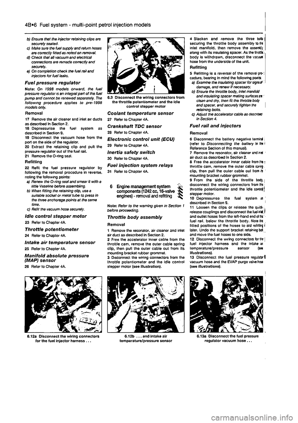
6.12a Disconnect the wiring connectors for the fuel injector harness ...
6.3 Disconnect the wiring connectors from the throttle potentiometer and the idle control stepper motor
Coolant temperature sensor 27 Refer to Chapter 4A. Crankshaft TDC sensor 28 Refer to Chapter 4A. Electronic control unit (ECU)
29 Refer to Chopter 4A.
Inertia safety switch 30 Refer to Chapter 4A. Fuel injection system relays 31 Refer to Chapter 4A.
6 Engine management system ^ components
(1242
cc,16-vatve S engines) - removal and refitting ^
Note: Refer to the warning given in Section t before proceeding.
Throttle body assembly
Removal 1 Remove the resonator, air cleaner and inlet air duct as described in Section 2. 2 Free Ihe accelerator inner cab
4 Slacken and remove the three bob j securing the throttle body assembly to ite inlet manifold. Ihen remove the assent?/ along with its insulating spacer. As the
throaii 1-
body is withdrawn, disconnect the vacuum hose from the underside of the unit. Refitting 5 Refitting is a reversal of the removal pi>: cedure, bearing in mind the following pants a) Examine the insulating spacer for signs d damage, and renew if necessary. b) Ensure the throttle body, inlet
manddd
and insulating spacer mating surfaces at -clean and dry. then fit the throttle
btxty
and spacer, and securely tighten the retaining bolts. c) Adjust Ute accelerator cable as desciter /nSecfw?4.
Fuel rail and injectors
Removal 6 Disconnect the battery negative termrul; (refer to Disconnecting the battery in ir*J Reference Section ol this manual), 7 Remove the resonator, air cleaner arid io«l 1 air duct as descnbed in Section 2. 8 Free the accelerator Inner cablc from l>*
1
throttle cam, remove the outer cable sprig. clip, then pull the outer cable out from
>H
mounting bracket rubber grommet, 9 From the side of the throttle bod/, | disconnect the wiring connectors from Ihs: throttle potentiometer and the idle cofttro^ stepper motor. 10 Oepressunse the fuel system si ' described in Section 9. ' 11 Loosen the clips or release tho quick-. release couplings and disconnect the fuel MdJ' and outlet hoses from the left-hand end oftfu fuel rail, below the throttle body. Note IM fitted positions ol the hoses to aid relirtirf i later. Undo the support bracket retaining bol and move the fuel hoses to one side. 12 Disconnect Ihe wiring connectors forth* fuel injector harness and the Intake an temperature/pressure sensor (m illustrations). 13 Disconnect the fuel pressure regulator-! vacuum hose and the EVAP purgo vaive h«* (see illustrations).
6.13a Disconnect the fuel pressure regulator vacuum hose...
Page 133 of 225
4A*2 Fuel system -
single-point
petrol Injection models
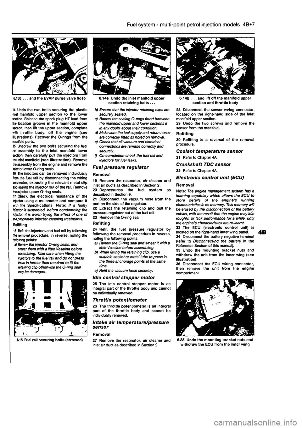
6.13b ... and tho EVAP purge valve hose
14 Undo the two bolls securing the plastic nlet manifold upper section to the lower section. Release the spark plug HT lead from Ihe location groove in the manifold upper section, then lift the upper section, complete with throttle body, off the engine (see illustrations). Recover the O-nngs from the manifold ports. 16 Unscrew the two bolts securing the fuel rail assembly to the Inlet manifold lower section, inen carefully pull the injectors from ttie inlet manifold (see Illustration). Remove
tt>e
assembly from the engine and remove the injector lower O-ring seals. t& The injectors can be removed individually from the fuel rail by disconnecting the wiring connector, extracting the relevant metal clip
ano
easing the injector out of the rail. Remove themjector upper O-ring seals. 17 Check the electrical resistance of the tractor using a multimeter and compare it with the Specifications. Note: If a faulty Rector fc suspected, before condemning Wie
Rector,
it is worth trying the effect of one of m
proprietary
injector-cleaning treatments. Refitting
15 Refit the injectors and fuel rail by following tie removal procedure, In reverse, noting the Mowing points:
4} Re/few
the Injector O-ring seals, and
smear
them with a little Vaseline before assembling. Take care when fitting the
injectors
to the fuel rail and do not press
them
in further than required to fit the
retaining
clip otherwise the O-ring
seal may
be damaged.
6.14a Undo the inlet manifold upper section retaining bolts ... b) Ensure that the injector retaining clips are securely seated. c) Renew the sealing O-nngs fitted between the manifold upper and lower sections if in any doubt about their condition. d) Make sure the fuel supply and return hoses are correctly fitted as noted on removal. e) Check that all vacuum and electrical connections are remade correctly and securely. f) On completion check the fuel rail and injectors tor fuel leaks.
Fuel pressure regulator
Removal 19 Remove the resonator, air cleaner and inlet air ducts as described In Section 2. 20 Depressurise the fuel system as described In Section 9. 21 Disconnect the vacuum hose from the port on the side of the regulator. 22 Extract the retaining clip and pull the pressure regulator out of the fuel rail. 23 Remove the O-ring seal. Refitting 24 Refit the fuel pressure regulator by following the removal procedure in reverse, noting the following points: a) Renew the O-ring
seaJ
and smear it with a little Vaseline before assembling. b) When fitting the retaining clip, use a suitable socket or metal tube to press in the three anchorage points at the same time. c) Refit the vacuum hose securely.
Idle control stepper motor 25 The idle control stepper motor is an Integral part of the throttle body and cannot be individually renewed.
Throttle potentiometer 26 The throttle potentiometer Is an integral part of the throttle body and cannot be individually renewed.
Intake air temperature/pressure sensor
Removal
6.14b ... and lift off the manifold upper section and throttle body 28 Disconnect the sensor wiring connector, located on the right-hand side of the Inlet manifold upper section. 29 Undo the two screws and remove the sensor from the manifold. Refitting 30 Refitting is a reversal of the removal procedure. Coolant temperature sensor 31 Refer to Chapter 4A.
Crankshaft TDC sensor 32 Refer to Chapter 4A.
Electronic control unit (ECU)
Removal Note: 77?e engine management system has a learning capability which allows the ECU to store details of the engine's running characteristics in Its memory. This memory will be erased by the disconnection of the battery cables, with the result that the engine may idle roughly, or lack performance for a while, until the engine's characteristics are re-learnt. 33 The ECU (electronic control unit) is located on the right-hand inner wing panel. 34 Disconnect the battery negative terminal (refer to Disconnecting the battery In the Reference Section of this manual). 35 Undo the mounting bracket nuts and withdraw the unit from the inner wing (see Illustration). 36 Disconnect the ECU wiring connector, then remove the unit from the engine compartment.
6.15 Fuel rail securing bolts (arrowed) 27 Remove the resonator, air cleaner and inlet air duct as described in Section 2. 6.35 Undo the mounting bracket nuts and withdraw the ECU from the inner wing
Page 140 of 225
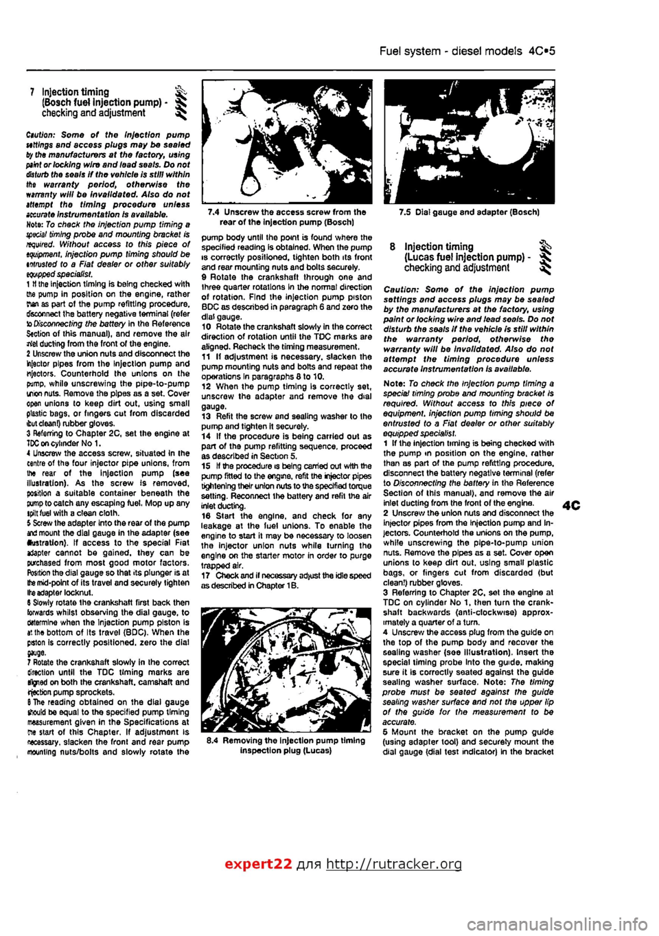
Fuel system - diesel models
4C*3
7.4 Unscrew the access screw from the 7.5 Dial gauge and adapter (Bosch) rear of the Injection pump (Bosch)
7 Injection timing ^ (Bosch fuel injection pump) -checking and adjustment ^
Caution: Some of the Injection pump uttlngs and access plugs may be sealed ty the manufacturers at the factory, using
paint
or locking wire and lead seals. Do not
disturb
the seals If the vehicle is still within the warranty period, otherwise the warranty will be invalidated. Also do not attempt the timing procedure unless
accurate
Instrumentation Is available. Note: To check the injection pump timing a special
timing
probe and mounting bracket is required. Without access to this piece of
tquipment.
injection pump timing should be intrusted to a Fiat dealer or other suitably
eqwpped
specialist. 1
H
the Injection timing is being checked with ffie pump in position on the engine, rather rian as part ot the pump refitting procedure, disconnect the battery negative terminal (refer to
Disconnecting
the battery in the Reference S«ction of this manual), and remove the air rtel ducting from the front of the engine. 2 Unscrew the union nuts and disconnect the injector pipes from the Injection pump and injectors. Counterhold the unions on the pump, while unscrewing the pipe-to-pump irion
nuts.
Remove the pipes as a set. Cover open unions to keep dirt out, using small plastic bags, or fingers cut from discarded
ibut clean!)
rubber gloves. 3 Referring to Chapter 2C, set the engine at
TDC on
cylinder No 1. 4 Unscrew the access screw, situated In the centre of the four injector pipe unions, from the rear of the Injection pump (see illustration). As the screw Is removed, position a suitable container beneath the
pump
to catch any escaping fuel, Mop up any tpilt fuel with a clean cloth. 5 Screw the adapter into the rear of the pump
and
mount the dial gauge in ihe adapter (see •ustration). If access to the special Fiat *Japter cannot be gained, they can be purchased from most good motor factors. Position the dial gauge so that its plunger is at
Ifce
mid-point of its travel and securely tighten Ite adapter locknut. 6 Slowly rotate the crankshaft first back then towards whilst observing the dial gauge, to ctotermlne when the Injection pump piston is
a',
the bottom of Its travel (BDC), When the pston Is correctly positioned, zero the dial
7 Rotate the crankshaft slowly in the correct direction until the TDC timing marks are tfjned on both the crankshaft, camshaft and rjecbon pump sprockets.
6
The reading obtained on the dial gauge should be equal to the specified pump timing measurement given in the Specifications at ew start of this Chapter, If adjustment is necessary, slacken the fronl and rear pump mounting nuts/bolts and slowly rotate the
pump body until the point is found where the specified reading Is obtained. When the pump is correctly posilioned, tighten both its front and rear mounting nuts and bolts securely. 9 Rotate the crankshaft through one and three quarter rotations in the normal direction of rotation. Find the injection pump piston BDC as described in paragraph 6 and zero the dial gauge. 10 Rotate the crankshaft slowly in the correct direction of rotation until the TDC marks are aligned. Recheck the timing measurement. 11 If adjustment is necessary, slacken the pump mounting nuts and bolts and repeat the operations In paragraphs 8 to 10. 12 When the pump timing Is correctly set, unscrew the adapter and remove the dial gauge. 13 Refit the screw and sealing washer to the pump and tighten it securely. 14 If the procedure is being carried out as part of the pump refitting sequence, proceed as described in Section 5, 15 If the procedure is being carried out with the pump fitted to the engine, refit the injector pipes tightening their union nuts to the specified torque setting. Reconnect the battery and refit the air inlet ducting. 16 Start the engine, and check for any leakage at the luel unions. To enable the engine to start it may be necessary to loosen the injector union nuts while turning tho engine on the starter motor in order to purge trapped air. 17 Check and if necessary adjust the idle speed as described in Chapter 1B.
8.4 Removing the injection pump timing inspection plug (Lucas)
8 injection timing ^ (Lucas fuel injection pump) - ^ checking
and
adjustment ^
Caution: Some of the injection pump settings and access plugs may be sealed by the manufacturers at the factory, using paint or locking wire and lead seo/s. Do not disturb the seals if the vehicle Is still within the warranty period, otherwise tho warranty will be Invalidated. Also do not affempf the timing procedure unless accurate instrumentation is available.
Note: To check the Injection pump timing a speciai timing probe and mounting bracket Is required. Without access to this piece of equipment, injection pump timing should be entrusted to a Fiat dealer or other suitably equipped specialist. 1 If the injection timing is being checked with the pump tn position on the engine, rather than as part of the pump refitting procedure, disconnect the battery negative terminal (refer to Disconnecting the battery in the Reference Section of this manual), and remove the air inlet ducting from the front of the engine. 2 Unscrew the union nuts and disconnect the injector pipes from the Injection pump and In-jectors. Counterhold the unions on the pump, while unscrewing the pipe-to-pump union nuts. Remove the pipes as a set. Cover open unions to keep dirt out. using smalt plastic bags, or fingers cut from discarded (but clean!) rubber gloves. 3 Referring to Chapter 2C, set the engine at TDC on cylinder No 1, then turn the crank-shaft backwards (anti-clockwise) approx-imately a quarter of a turn. 4 Unscrew the access plug from the guide on the top of the pump body and recover the sealing washer (soe Illustration). Insert the special liming probe Into the guide, making sure it Ib correctly seated against the guide seating washer surface. Note: The timing probe must be seated against the guide sealing washer surface and not the upper lip of the guide for the measurement to be accurate. 5 Mount the bracket on the pump guide (using adapter tool) and securely mount the dial gauge {dial test indicator) In the bracket
expert22 fl/i* http://rutracker.org
Page 141 of 225
Fuel system - diesel models 4C*3
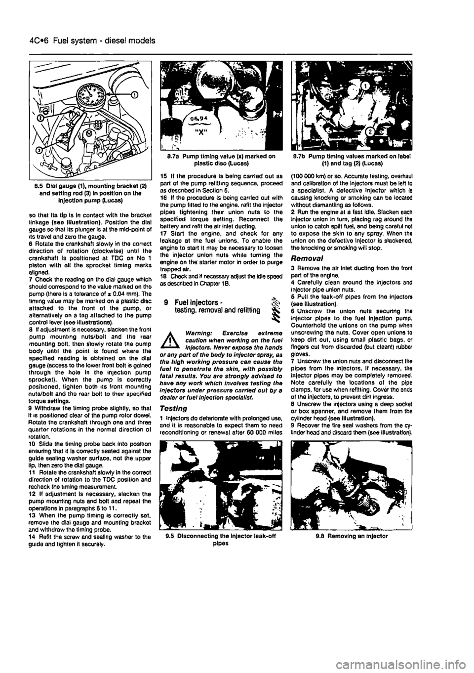
8.5 Dial gauge (1), mounting bracket (2) and setting rod (3) In position on the injection pump (Lucas)
so that Its tip Is In contact with the bracket linkage (see Illustration). Position the dial gauge so that its plunger is at the mid-point of its travel and zero the gauge. 6 Rotate the crankshaft slowly in the correct direction of rotation (clockwise) until the crankshaft is positioned at TDC on No 1 piston with ell the sprocket timing marks aligned. 7 Check the reading on the dial gauge which should correspond to the value marked on the pump (there is a tolerance of * 0.04 mm). The timing value may be marked on a plastic disc attached to the front of the pump, or alternatively on a tag attached to Ihe pump control lever (see illustrations). 8 If adjustment is necessary, slacken the front pump mounting nuts/bolt and the raar mounting bolt, then slowly rotate tne pump body until the point is found where the specified reading is obtained on the dial gauge (access to the lower front bolt is gained through the hole in the injection pump sprocket). When the pump Is correctly positioned, tighten both its front mounting nuta/bolt and the rear bolt to their specified torque settings. 9 Withdraw the timing probe slightly, so that it
8.7a Pump timing value (x) marked on plastic diso (Lucas)
15 If the procedure is being carried out as part of the pump refilling sequence, proceed as described in Section 5. 16 If the procedure is being carried out with the pump fitted to the engine, refit the injector pipes tightening their union nuts to the specified torque setting. Reconnect the battery and refit the air inlet ducting. 17 Start the engine, and check for any leakage at the fuel unions. To enable the engine to start it may be necessary to loosen tho injector union nuts while turning the engine on the starter motor in order to purge trapped air. 18 Check and If necessary adjust the Idle speed as described In Chapter 1B.
9 Fuel Injectors -testing, removal and refitting Sk ^
A
Warning: Exercise extreme caution when working on the fuel injectors. Never expose the hands or any part of the body to Injector spray, as the high working pressure can cause the fuel to pen ot rate the skin, with possibly fatal results. You are strongly advised to have any work which involves testing the injectors under pressure carried out by a dealer or fuel Injection specie list.
Testing 1 Injectors do deteriorate with prolonged uso, and it is reasonable to expect them to need reconditioning or renewal after 60 000 miles
8.7b Pump timing values marked on label (1) and tag (2) (Lucas)
(100 000 km) or so. Accurate testing, overhaul and calibration of the Injectors must be left to a specialist. A defective injector which Is causing knocking or smoking can be located without dismantling as follows. 2 Run the engine at a fast idle. Slacken each Injector union In turn, placing rag around the union to catch spilt fuel, and being careful not to exposa the skin to any spray. When tho union on the defective Injector is slackened, the knocking or smoking will stop.
Removal 3 Remove ihe air Inlet ducting from tho front part of the onglne. 4 Carefully clean around the Injectors and injector pipe union nuts. 5 Pull the leak-off pipes from the injectors (see illustration). 6 Unscrow the union nuts securing Ihe injector pipes to the fuel Injection pump. Counterhold the unions on the pump when unscrewing the nuts. Cover open unions lo keep dirt out, using small plastic bags, or fingers cut from discarded (but clean!) rubber gloves. 7 Unscrew the union nuts and disconnect the pipes from the ln|ectors, If necessary, the Injector pipes may be completely removed-Note carefully the locations of the pipe clamps, for use when refitting. Cover tho onds ot (he injectors, to prevent dirt ingress. 8 Unscrew the injectors using a deep socket or box spanner, and remove Ihem from the cylinder head (see Illustration). 9 Recover the tire seal washers from the cy-linder head and discard them (see illustration).
9.5 Disconnecting the Injector leak-off pipes 9.8 Removing an injector
Page 150 of 225
5A«2 Starting and charging systems
Maintenance-free battery -charging Note: The following is intended as a guide only. Always refer to the manufacturer's recommendations (often printed on a label attached to the battery) before charging a battery. 13 This battery type takes considerably longer lo fully recharge than the standard type, the time taken being dependent on the extent of discharge, but it can take anything
up
to three days. 14 A constant voltage type charger is required, tooe set, when connected, to 13.9 to 14.9 votts wth a charger current below 25 amps. Using
mis
method, the battery should be usable within three hours, giving a voltage reading of 12.5 vofts. but this Is for a partially discharged battery and, as mentioned, full charging can
take
considerably longer. 15 If Ihe battery is to be charged from a fully discharged state {condition reading loss lhan 12.2 volts), have it recharged by your FIAT dealer or local automotive electrician, as Ihe charge rate is higher and constant super-vision during charging Is necessary.
3 Battery -removal and refitting
Note: Refer to Disconnecting the battery in ifte Reference Section of this manual before proceeding.
Removal 1 Slacken the clamp bolts and disconnect the ctamp from the battery negative (earth) terminal. 2 Remove the insulation cover (where fitted)
and
disconnect the positive terminal lead(s) in
Die same
way. 3 At the base of the battery, unscrew the bolt from the battery holding clamp plate and remove the clamp plate (see Illustration). A Remove the battery from Ihe engine compartment. 5 II necessary the mounting tray may be removed by unscrewing the bolts. On diesel models it will be necessary to remove the relay guard bolts as well.
Refitting 6 Refitting is a reversal of removal but make sure that the positive terminal is connected first followed by the negative terminal.
4 Alternator/charging system - >%•> testing in vehicle
Note: Refer to the warnings given in Safety first! and in Section 1 of this Chapter before starting work. 1 If the ignition warning light fails to Illuminate when the ignition is switched on, first check the alternator wiring connections for security. If satisfactory, check that the warning light bulb has not blown, and that the bulbholder is secure in its location in the instrument panel. If the light still fails to illuminate, check the continuity of the warning light feed wire from the alternator to the bulbholder. If all is satisfactory, the alternator is at fault and should be renewed or taken to an auto-electrician for testing and repair. 2 If the ignition warning light Illuminates when the engine Is running, stop the engine and check that the drivebelt is correctly tensioned (see Chapter 1A or 18) and that the alternator connections are secure. If all is so far satisfactory, have the alternator checked by an auto-electrician. 3 If the alternator output is suspect even though the warning light functions correctly, the regulated voltage may be checked as follows. 4 Connect a voltmeter across the battery terminals and start the engine. 5 Increase the engine speed until the voltmeter reading remains steady; the reading should be approximately 12 to 13 volts, and no more than 14 volts. 6 Switch on as many electrical accessories (eg. the headlights, heated rear window and heater blower) as possible, and check that the alternator maintains the regulated voltage at around 13 to 14 volts. 7 If ihe regulated voltage is not as stated, the fault may be due to worn brushes, weak brush springs, e faulty voltage regulator, a faulty diode, a severed phase winding or worn or damaged slip rings. The alternator should be renewed or taken to an auto-electrician for testing and repair.
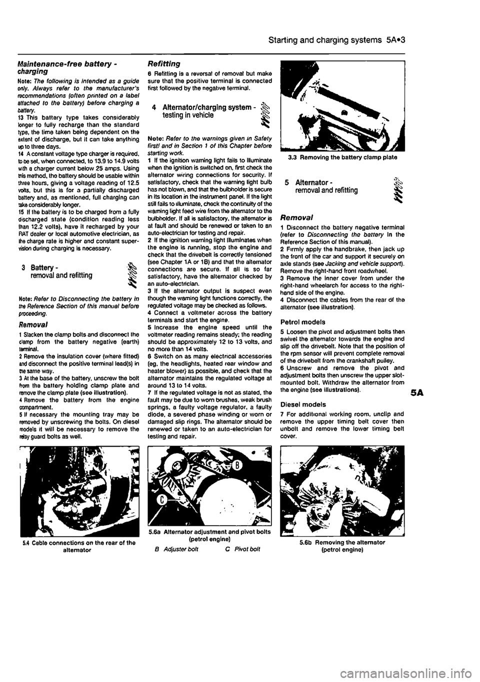
3.3 Removing the battery clamp plate
5 Alternator -removal and refitting
Removal 1 Disconnect the battery negative terminal {refer to Disconnecting the battery In the Reference Section of this manual). 2 Firmly apply the handbrake, then jack up the front of the car and support it securely on axle stands (see Jacking and vehicle support). Remove tho right-hand front roadwheel. 3 Remove Ihe Inner cover from under the right-hand wheelarch for access to tho right-hand side of the engine. 4 Disconnect the cables from the rear Of the alternator (see illustration).
Petrol models 5 Loosen the pivot and adjustment bolts then swivel the alternator towards the engine and slip off the drivebelt. Note that the position of the rpm sensor will prevent complete removal of the drivebelt from the crankshaft puiley. 6 Unscrew and remove the pivot and adjustment bolts then unscrew the upper slot-mounted bolt. Withdraw the alternator from the engine (see illustrations).
Diesel models 7 For additional working room, unclip and remove the upper timing belt cover then unbolt and remove the lower timing belt cover.
5.4 Cable connections on the rear of the alternator
5.6a Alternator adjustment and pivot bolts (petrol engine) B Adjuster bolt C Pivot bolt 5.6b Removing the alternator (petrol engine)
Page 159 of 225
6*2 Clutch
3 Clutch cable -removal and refitting
Note: This procedure applies to models fitted with a cabfe-opemted dutch
release mechanism.
Removal 1 Remove the battery and tray as described In Chapter SA. If necessary, also remove the Inlet air ducting for Improved access as described In the relevant part of Chapter 4. 2 Unscrew the adjustment locknut and adjuster nut from the end of the cable fitting, (hen release the inner and outer cables from the transmission housing. Note the position of the damper biock. 3 Working Inside the vehicle, unhook the inner cable from the top of the clutch pedaL 4 Returning to the engine compartment, unscrew the nuts securing the outer cable to the bulkhead, then withdraw the cable assembly from the engine compartment. Refitting 5 Apply a smear of multi-purpose grease to the cable end fittings, then pass the cable through the bulkhead. Refit and tighten the nuts. 6 Inside the vehicle hook the inner cable onto the top of the clutch pedal. 7 in the engine compartment, attach the outer cable to the transmission housing and refit the damper block and nuts lo Ihe inner cable end. fi Adjust the cable as described in Section 2. 9 Refit the air ducting and battery with reference to Chapters 4 and 5A
4 Clutch hydraulic system -
i
Note: This procedure applies to models fitted with the hydraulicalty-operated clutch release mechanism.
A
Warning: Hydraulic fluid Is poisonous; thoroughly wash off spllfs from bare skin without delay. Seek Immediate medical advice If any fluid is swallowed or gets into the eyes. Certain types of hydraulic fluid are Inflammable and may ignite when brought into contact with hot components; when servicing any hydraulic system, It is safest to assume that the fluid IS Inflammable, and to take precautions against the risk of fire as though ft were petrof that was being handled. Hydraulic fluid Is an effective paint stripper and will also attack many plastics. If spillage occurs onto painted bodywork or fittings, ft should be washed off Immediately, using copious quantities of fresh water. It Is also hygroscopic - It can absorb moisture from the air, which then renders it useless. Old fluid may have
suffered contamination, and should never be re-used. When topping-up or renewing tho fluid, always use tha recommended grade, and ensure that It comes from a new seated container. General information 1 Whenever the clutch hydraulic lines are disconnected for service or repair, a certain amount of air will enter the system. The presence of air In any hydraulic system will Introduce a degree of elasticity, and in the clutch system this will translate into poor pedal feel and reduced travel, leading to inefficient gear changes and even clutch system failure. For this reason, the hydraulic lines must be sealed using hose clamps before any work la carried out and then on completion, topped up and bled to remove any air bubbles. 2 To seal off Ihe hydraulic supply to tha clutch slave cylinder, fit a proprietary brake hose clamp to the flexible section of the hose located over the transmission and tighten it securely. It will be necessary to remove the battery and battery tray to access the hose. 3 The most effective way of bleeding the clutch hydraulic system is to use a pressure brake bleeding kit. These are readily available in motor accessories shops and are extremely effective: the following sub-section describes bleeding the clutch system using such a kit. The alternative method is to bleed the system by depressing tho clutch pedal • refer to Chapter 9. Section 11, for details of this method.
Bleeding 4 Remove the protective cap from Ihe bleed nipple on the slave cylinder. Access can be improved by removing the battery and tray with reference to Chapter 5A. 5 Fit a ring spanner over the bleed nipple head, but do not slacken it at this point. Connect a length of dear plastic hose over the nipple and insert the other end into a clean container. Pour hydraulic fluid into the container, such that the end of the hose is covered. 6 Following the manufacturer's instructions, pour hydraulic fluid into the bleeding kit vessel 7 Unscrew the vehicle's fluid reservoir cap, then connect Ihe bleeding kit fluid supply hose to the reservoir. 8 Connect the pressure hose to a supply of compressed air - a spare tyre is a convenient source. Caution: Check that the pressure In the tyre does not exceed the maximum supply pressure quoted by the kit manufacturer, let soma sir escape to reduce the pressure, if necessary. Gently open the air valve and allow the air and fluid pressures to equalise. Check that there ere no teaks before proceeding. 9 Using the spanner, slacken the bleed pipe nipple until fluid and air bubbles can be seen to flow through the tube, into the container.
Maintain a steady flow until the emerging fluid la free of air bubbles; keep a watchful eye on the level of fluid in the bleeding kit vessel and the vehicle's fluid reservoir • if it Is allowed to drop too low, air may be forced into the system, defeating the object of the exercise. To refill the vessel, turn off the compressed air supply, remove the lid and pour In en appropriate quantity of clean fluid from a new container - do not re-use the fluid collected in the receiving container. Repeat as necessary until the ejected fluid is bubble-free. 10 On completion, pump the olutch pedal several times to assess its feel and travel. If firm, constant pedal resistance is not felt throughout the pedal stroke, it i6 probable that air Is still present in the system - repeat the bleeding procedure untii the pedal feel is restored. 11 Depressurise the bleeding kit and remove it from the vehicle. At this point, the fluid reservoir may be over-full; the excess should be removed using a clean pipette to reduce the level to the MAX mark. 12 Tighten the bleed pipe nipple using the spanner and remove the receiving container. Refit the protective cap. 13 On completion, assess the feel of the clutch pedal; if it exhibits any sponginess or looseness, further bleeding may be required. 14 Where removed, refit the battery and tray. 15 Finally, road test the vehicle and check the operation of the clutch system whilst changing up and down through the gsar9. whilst pulling away from a standstill and from a hill start.
5 Clutch master cylinder - & removal
and
refitting 5 S Note: This procedure applies to models
fitted
with the hydraulically-operated dutch
release
mechanism. Note: Refer to the warning at Ihe beginning
of
Section 4 regarding the hazards of
working
with hydraulic fluid.
Removal 1 Disconnect the battery negative terminal (refer lo Disconnecting the battery in the Reference Section of this manual). 2 Remove the air cleaner and air ducting as described in the relevant Part of Chapter 4. 3 For improved access on petrol engine models, remove the alternator as described In Chapter 5A. 4 Fit a brake hose clamp to the hose between the hydraulic fluid reservoir and the clutch master cylinder. Alternatively syphon ail the fluid from the reservoir. 5 Disconnect the fluid supply hose at the master cylinder, then unscrew the union nut and disconnect the hydraulic pipe from the cylinder outlet. Be prepared for some fluid loss by placing some rags beneath the master cylinder.
Page 160 of 225
Clutch 6*3
6 WorWng inside the vehicle, extract the split pin and remove the washer securing the master cylinder pushrod to the clutch pedal. Dsoonnect the pushrod from the pivot. 7 Have an assistant support the master cylinder In the engine compartment, then unscrew the mounting bolts. Withdraw the master cylinder from the engine compartment, 8 II is not possible to obtain an overhaul kit from Flat however some motor factors may be abls to supply one. Follow the Instructions with the repair kit if obtained.
Refitting 9 Refit the clutch master cylinder by following ihe removal procedure In reverse, noting the following. a) Apply a
Utile
high-melting point grease to the clutch pedal pivot. b) Tighten the mounting bolts and union nut securely. cj Fit a new split pin to the pushrod. d) Where removed, refit the alternator
as
described In Chapter 5A e) On completion bleed the clutch hydraulic system as descnbed in Section
A.
7 Clutch assembly -
removal,
inspection
and
refitting
S Clutch slave cylinder-removal and refitting
Note: This procedure applies to models fitted
ivrth
the hydraulically-operated clutch release mechanism. Note: Refer to the warning at the beginning
of
Section A regarding the hazards of working
with
hydraulic fluid.
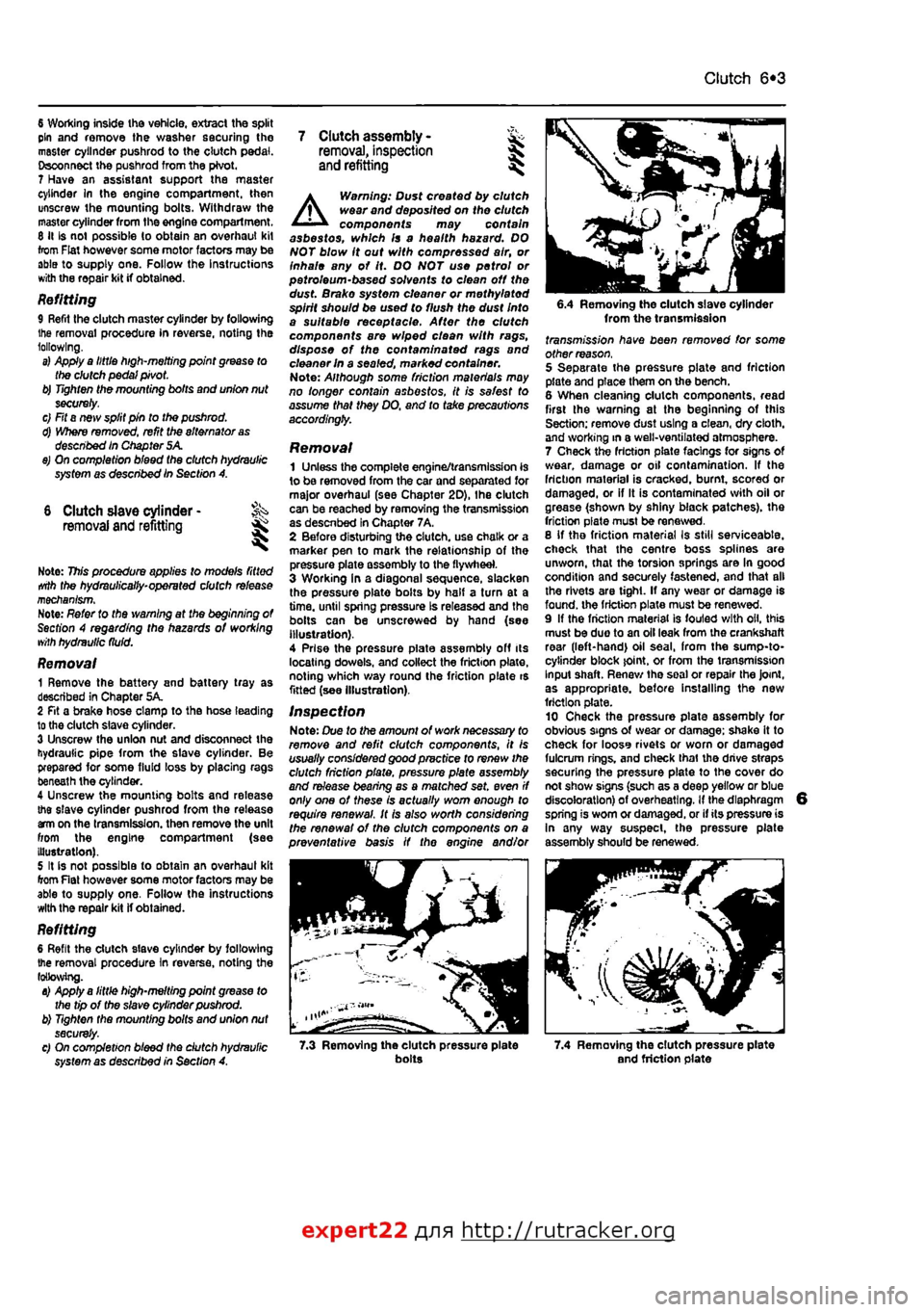
Removal 1 Remove the battery and battery tray as described in Chapter 5A. 2 Fit a brake hose clamp to tha hose leading to the clutch slave cylinder. 3 Unscrew the union nut and disconnect the hydraulic pipe from the slave cylinder. Be prepared for some fluid loss by placing rags beneath the cylinder. 4 Unscrew the mounting bolts and release the slave cylinder pushrod from the release am on the transmission, then remove the unit from the engine compartment (see Illustration). 5 It is not possible to obtain an overhaul kit from Flat however some motor factors may be able to supply one. Follow tha instructions with the repair kit if obtained.
Refitting 6 Refit the clutch slave cylinder by following the removal procedure In reverse, noting the following. a) Apply a little high-melting point grease to the tip of the slave cylinder pushrod. b) Tighten the mounting bolts and union nut securely. c) On completion bleed the dutch hydraulic system as described in Section A.
A
Warning: Dust created by clutch wear and deposited on the clutch components may contain asbestos, which Is a health hazard. DO NOT blow it out with compressed air, or inhale any of it. DO NOT use petrol or petroleum-based solvents to clean off the dust. Brake system cleaner or methylated spirit should be used to flush the dust Into a suitable receptacle. After the clutch components are wiped clean with rags, dispose of the confam/nafed rags and cleaner In a sealed, marked container. Note: Although some friction materials may no longer contain asbestos, it is safest to assume that they DO. and to take precautions accordingly.
Removal 1 Unless the complete engine/transmission is to be removed from the car and separated for major overhaul (see Chapter 2D), Ihe clutch can be reached by removing the transmission as descnbed in Chapter 7A, 2 Before disturbing the clutch, use chalk or a marker pen to mark the relationship of the pressure plate assembly to the flywheel. 3 Working In a diagonal sequence, slacken the pressure plate bolts by half a turn at a time, until spring pressure Is released and the bolls can be unscrewed by hand (see Illustration). 4 Prise the pressure piate assembly off its locating dowels, and collect the friction plate, noting which way round the friction plate is fitted (see Illustration).
Inspection Note: Due to the amount of work necessary to remove and refit clutch components, It is usually considered good practice to renew the clutch friction plate, pressure plate assembly and release bearing as a matched set. even if only one of these is actually worn enough to require renewal. It Is also worth considering the renewal of the clutch components on a preventative basis if the engine and/or
6.4 Removing the clutch slave cylinder from the transmission fransmj'ss/on have been removed for some other reason. 5 Separate the pressure plate and friction plate and place them on the bench. 6 When cleaning clutch components, read first the warning at the beginning of this Section; remove dust using a clean, dry cloth, and working in a well-ventilated atmosphere. 7 Check the friction plats facings for signs Of wear, damage or oil contamination. If the friction material is cracked, burnt, scored or damaged, or if It is contaminated with oil or grease (shown by shiny black patches), the friction plate must be renewed. 8 If tho friction material Is still serviceable, check that the centre boss splines are unworn, that the torsion springs are In good condition and securely fastened, and that all the rivets are tight. If any wear or damage is found, the friction plate must be renewed. 9 If the friction material is fouled with oil, this must be duo to an oil leak from the crankshaft rear (left-hand) oil seal, from the sump-to-cytinder block joint, or from the transmission Input shaft. Renew tha soal or repair the Joint, as appropriate, before Installing the new friction plate. 10 Check tha pressure plate assembly for obvious signs of wear or damage; shake it to check for looss rivets or worn or damaged fulcrum rings, and check thai the drive straps securing the pressure plate to the cover do not show signs (such as a deep yellow or blue discoloration) of overheating. If the diaphragm spring is worn or damaged, or if its pressure is In any way suspect, the pressure plate assembly should be renewed.
7.3 Removing the clutch pressure plate bolts 7.4 Removing the clutch pressure plate and friction plate
expert22 {
a http://rutracker.org
Page 174 of 225
Driveshafts 8*3
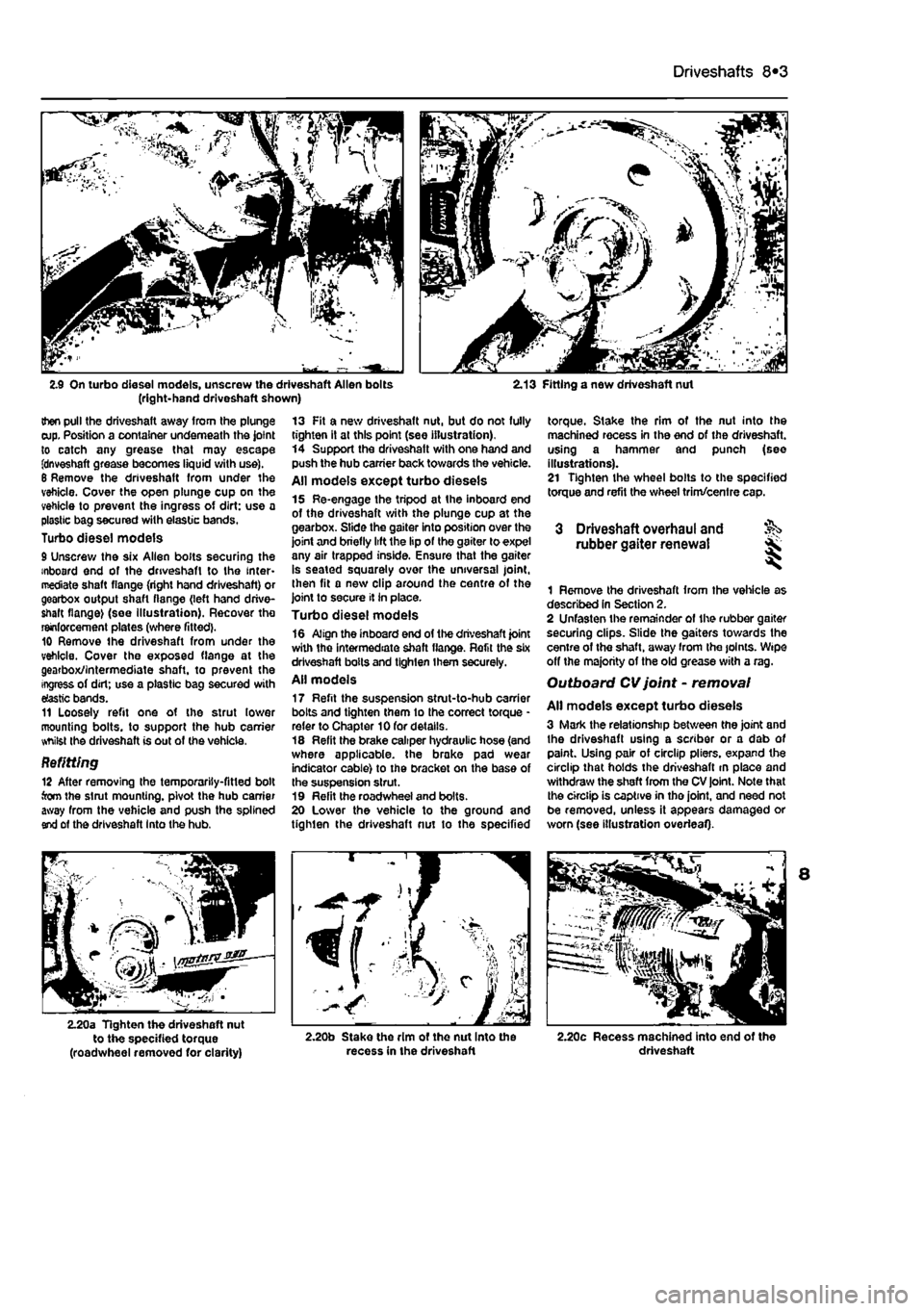
2.9 On turbo diesel models, unscrew the driveshaft Allen bolts (right-hand driveshaft shown) 2.13 Fitting a new driveshaft nut
then pull the driveshaft away from the plunge cup. Position a container underneath the joint to catch any grease that may escape fdnveshaft grease becomes liquid with use). 6 Remove the driveshaft from under the vehicle. Cover the open plunge cup on the vehicle to prevent the ingress of dirt: use a plastic bag secured with elastic bands. Turbo diesel models 9 Unscrew the six Allen bolts securing the inboard end of the driveshaft to the inter-mediate shaft flange (right hand driveshaft) or gearbox output shaft flange (left hand drive-shaft flange) (see Illustration). Recover tho reinforcement plates (where fitted). 10 Remove the driveshaft from under the vehicle. Cover the exposed flange at the gearbox/intermediate shaft, to prevent the ingress of dirt; use a plastic bag secured with elastic bands. 11 Loosely refit one of the strut lower mounting bolts, to support the hub carrier whilst the driveshaft is out of the vehicle.
Befitting 12 After removing the temporarily-fitted bolt torn the strut mounting, pivot the hub carrier away from the vehicle and push the splined end of the driveshaft Into the hub.
13 Fit a new driveshaft nut, but do not fully tighten it at this point (see illustration). 14 Support the driveshatt with one hand and push the hub carrier back towards the vehicle. All models except turbo diesels 15 Re-engage the tripod at the inboard end of the driveshaft with the plunge cup at the gearbox. Slide the gaiter into position over the joint and briefly lift the lip of the gaiter to expel any air trapped inside. Ensure that the gaiter is seated squarely over the universal joint, then fit a new clip around the centre of the joint to secure it in place. Turbo diesel models 16 Align the inboard end of the driveshaft joint with the intermediate shaft flange. Refit the six driveshaft bolts and tighten them securely. All models 17 Refit the suspension strut-to-hub carrier bolts and tighten them to the correct torque * refer to Chapter 10 for details. 18 Refit the brake caliper hydraulic hose (and where applicable, the brake pad wear indicator cable) to the bracket on the base of the suspension strut. 19 Refit the roadwheel and bolts. 20 Lower the vehicle to the ground and tighten the driveshaft nut to the specified
torque. Stake the rim of the nut into the machined recess in the end of the driveshaft. using a hammer and punch (see illustrations). 21 Tighten the wheel bolts to the specified torque and refit the wheel trim/centre cap.
3 Driveshaft overhaul and rubber gaiter renewal
1 Remove the driveshaft from the vehicle as described In Section 2. 2 Unfasten the remainder of the rubber gaiter securing clips. Slide the gaiters towards the centre of the shaft, away from Ihe joints. Wipe off the majority of the old grease with a rag. Outboard CV joint - removal
All models except turbo diesels 3 Mark the relationship between the joint and the driveshaft using a scriber or a dab of paint. Using pair of circlip pliers, expand the circlip that holds the driveshaft m place and withdraw the shaft from the CV joint. Note that the circlip is captive in tho joint, and need not be removed, unless it appears damaged or worn (see illustration overleaf).
2.20a Tighten the driveshaft nut to the specified torque (roadwheel removed for clarity) 2.20b Stake the rim ot the nut Into the recess in the driveshaft 2.20c Recess machined into end of the driveshaft