Trem FIAT PUNTO 1998 176 / 1.G Workshop Manual
[x] Cancel search | Manufacturer: FIAT, Model Year: 1998, Model line: PUNTO, Model: FIAT PUNTO 1998 176 / 1.GPages: 225, PDF Size: 18.54 MB
Page 6 of 225
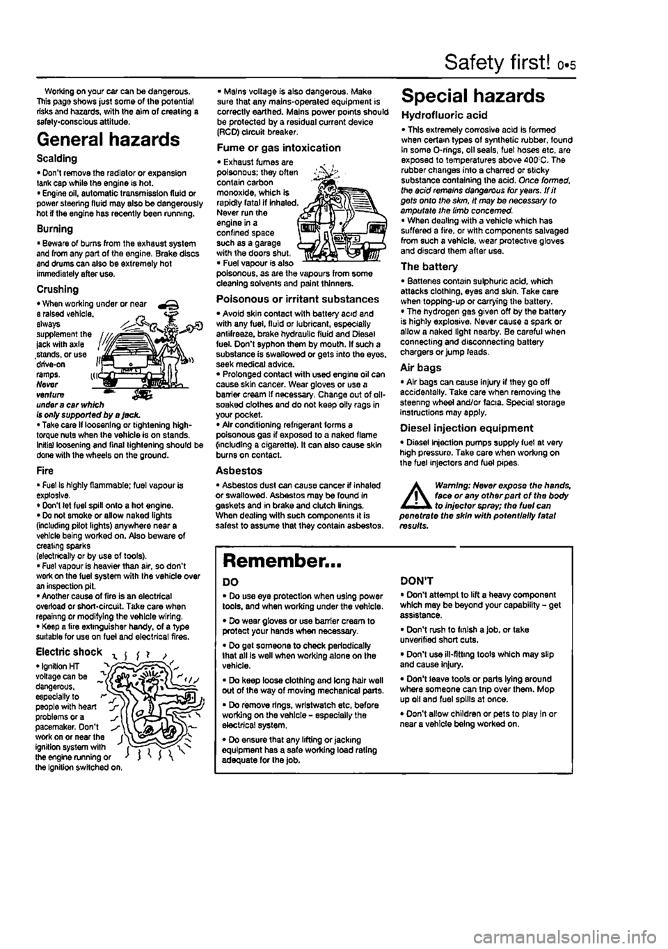
Safety first! 0.5
Working on your ear can be dangerous. This page shows just some of the potential risks and hazards, with the aim of creating a safety-conscious attitude.
General hazards
Scalding • Don't remove the radiator or expansion tank cap while the engine is hot. • Engine oil, automatic transmission fluid or power steering fluid may also be dangerously hot if the engine has recently been running.
Burning • Beware of burns from the exhau3t system and from any part of the engine. Brake discs and drums can also be extremely hot immediately after use.
Crushing • When working under or near a raised vehicle. ~ always supplement the ' ' -jack with axle stands, or use ... drive-on i'j ramps. kr Never venture ™ under
a
car
vv/j/ch
Is only supported by a jack. • Take card if loosening or tightening high-torque nuts when the vehicle is on stands. Initial loosening and final tightening should be done with the wheels on the ground.
Fire • Fuel Is highly flammable; fuel vapour is explosive. • Don't (et fuel spill onto a hot engine. • Do not smoke or allow naked lights (including pilot lights) anywhere near a vehicle being worked on. Also beware of creating sparks (electrically or by use of toots). • Fuel vapour is heavier than air, so don't work on the fuel system with the vehicle over an inspection pit. • Another cause of fire is an electrical overload or short-circuit. Take care when repainng or modifying the vehicle wiring. • Keep a fire extinguisher handy, of a type suitable for use on fuel and electrical fires.
Electric shock x ^ ^ ? , • Ignition HT _ " voltage can be ^ dangerous, ~ especially to > people with heart problems or a pacemaker. Don't work on or near the f^ ignition system with fT") the engine running or ' J ' J the Ignition switched on.
• Mains voltage is also dangerous. Make sure that any mains-operated equipment is correctly earthed. Mains power points should be protected by a residual current device (RCD) circuit breaker.
Fume or gas intoxication • Exhaust fumes are poisonous: they often contain carbon monoxide, which is rapidly fatal if inhaled. Never run the engine in a confined space such as a garage with the doors shut, • Fuel vapour is also poisonous, as are the vapours from some cleaning solvents and paint thinners.
Poisonous or irritant substances • Avoid skin contact with battery acid and with any fuel, fluid or lubricant, especially antifreeze, brake hydraulic fluid and Diesel fuel. Don't syphon them by mouth. If such a substance is swallowed or gets into the eyes, seek medical advice. « Prolonged contact with used engine oil can cause skin cancer. Wear gloves or use a barrier cream If necessary. Change out of oll-soaked clothes and do not keep oily rags in your pocket. • Air conditioning refrigerant forms a poisonous gas if exposed to a naked flame {including a cigarette). It can also cause skin burns on contact.
Asbestos • Asbestos dust can cause cancer if inhaled or swallowed. Asbestos may be found In gaskets and in brake and clutch linings. When dealing with soch components It is safest to assume that they contain asbestos.
Special hazards
Hydrofluoric acid • This extremely corrosive acid is formed when cerlam types of synthetic rubber, found In some O-rings, oil seals, fuel hoses etc. are exposed to temperatures above 400;C. The rubber changes into a charred or sticky substance containing the acid. Once formed, the acid remains dangerous for years, tfit gets onto the skin, it may be necessary to amputate the limb concerned. • When dealing with a vehicle which has suffered a fire, or with components salvaged from such a vehicle, wear protective gloves and discard them after use.
The battery • Batteries contain sulphuric acid, which attacks clothing, eyes and skin. Take care when topping-up or carrying the battery. • The hydrogen gas given off by the battery is highly explosive. Never cause a spark or allow a naked light nearby. Be careful when connecting and disconnecting battery chargers or jump leads.
Air bags • Air bags can cause injury if they go off accidentally. Take care when removing the steenng wheel and/or facia. Special storage instructions may apply.
Diesel injection equipment • Diesel injection pumps supply fuel at very high pressure. Take care when working on the fuel injectors and fuel pipes.
A
Warning: Never expose the hands, face or any otfterpart of the body to injector spray; the fuel can penetrate the skin with potentially fatal results.
Remember...
DO • Do use eye protection when using power tools, and when working under the vehicle. • Do wear gloves or use barrier cream to protect your hands when necessary. • Do get someone to check periodically that all is well when working alone on the vehicle. • Do keep loose clothing and long hair well out of the way of moving mechanical parts. • Do remove rings, wrtstwatch etc. before working on the vehicle - especially the electrical system, • Do ensure that any lifting or jacking equipment has a safe working load rating adequate for the job.
DON'T • Don't attempt to lift a heavy component which may be beyond your capability - get assistance. • Don't rush to finish a job. or take unverified short cuts. • Don't use ill-fitting toots which may slip and cause injury. • Don't leave tools or parts lying around where someone can trip over them. Mop up oil and fuel spills at once. • Don't allow children or pets to play In or near a vehicle being worked on.
Page 14 of 225
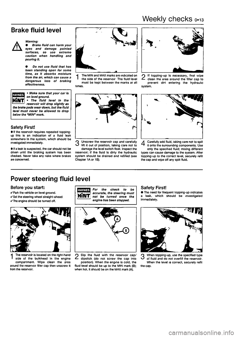
Weekly checks 0.13
Brake fluid level
A
Warning: • Brake fluid can harm your eyes and damage painted surfaces, so use extreme caution when handling and pouting it.
• Do not use fluid that has been standing open for so mo time, as It absorbs moisture from the air, which can cause a dangerous loss of braking effectiveness.
Mpmna * Make sure that your car Is I on level ground. HiNTi * Th* ffftt 'eve/ In the reservoir will drop slightly as
I
The MIN and MAX marks are indicated on the side of Ihe reservoir The fluid level must be kept between the marks at all times.
2
11 topping-up is necessary, first wipe clean the area around the filler cap to prevent dirt entering the hydraulic system.
the brake pads wear down, but the fluid level must never be allowed to drop below the "MIN" mark.
Safety First! • If the reservoir requires repeated topping* up this is an indication of a fluid leak somev/here In the system, which should be investigated immediately.
• If a leak is suspected, the car should not be driven until the braking system has been checked. Never take any risks where brakes are concerned.
Unscrew the reservoir cap and carefully lift it out of position, taking care not to damage the level switch float. Inspect the reservoir: if the fluid Is dirty Ihe hydraulic system should be drained and refilled (see Chapter 1A or 1B).
4
Carefully add fluid, taking care not to spill it onto the surrounding components, Use only the specified fluid; mixing different types can cause damage to the system. After topping-up to the correct level, secureiy refit the cap and wipe off any spilt fluid.
Power steering fluid level
Before you start: •Park the vehicle on level ground. • Set the steering wheel straight-ahead. •
The
engine should be turned off.
I
The reservoir is located on the right-hand side of the bulkhead in the engine compartment. Wipe clean the area around the reservoir filler cap then unscrew It from the reservoir.
For the check to be accurate, the steering must HlHT; not be turned once the engine has been stopped.
2
Dip the fluid with the reservoir cap/ dipstick (do not screw the cap into position). When the engine is cold, the fluid level should be up to Ihe MIN mark (B): when hot. it should be on the MAX mark (A).
Safety First! • The need for frequent topping-up indicates a leak, which should be investigated immediately.
3
When topping-up, use the specified type of lluid and do noi overfill the reservoir. When the level is correct, securely refit the cap.
Page 32 of 225
Every 20 000 miles - petrol models 1A.13
20 Ignition system check
81
21 Engine management system check
A
Warning: Voltages produced by an electronic ignition system are considerably higher than those produced by conventional ignition systems. Extreme care must be taken when working on the system with the Ignition switched on. Persons with surgically-Implanted cardiac pacemaker devices should keep well clear of the ignition circuits, components and test oquipment. 1 The ignition system components should be checked for damage or deterioration as follows.
General component check 2 The spark plug (HT) leads should be checked whenever new spark plugs are fitted. 3 Pull the leads from the plugs by gripping
the end
fitting, not the lead, otherwise the lead connection may be fractured.
Ensure that the leads are i numbered before removing i them, to avoid confusion when refitting
4 Check Inside the end fitting for signs of corrosion, which will look like a white crusty powder. Push the end fitting back onto the spark plug, ensuring that it is a tight fit on the plug. if not, remove the lead again and use pliers to carefully crimp the metal connector inside the end fitting until it fits securely on the
end
of the spark plug. 5 Using a clean rag, wipe Ihe emlre length of the lead to remove any built-up dirt and grease. Once the lead is clean, check for bums, cracks and other damage. Do not bend the lead excessively, nor pull the lead lengthways - the conductor inside might break. 6 Disconnect the other end of the lead from the ignition coll. Again, pull only on the end fitting. Check for corrosion and a tight fit in the
same
manner as the spark plug end. Refit the bad securely on completion. 7 Check the remaining leads one at a time, in
ihe same
way. 8 if new spark plug (HT) leads are required, purchase a set for your specific car and engine. 9 Even with the ignition system In first-class condition, some engines may still occasionally experience poor starting attributable to damp ignition components. To disperse moisture, a water-dispersant aerosol should be liberally
Ignition timing -
check
and adjustment 10 Check the ignition timing as described In Chapter 58.
1 This check is part of the manufacturer's maintenance schedule, and Involves testing Ihe engine management system using special dedicated test equipment. Such testing will allow the test equipment to read any fault codes stored in the electronic control unit memory. 2 Unless a fault is suspected, this test te not essential, although it should be noted that it is recommended by the manufacturers. 3 If access to suitable test equipment is not possible, make a thorough check of all ignition, fuel and emission control system components, hoses, and wiring, for security and obvious signs of damage. Further details of the fuet system, emission control system and ignition system can be .found In the relevant parts of Chapters 4 and 5.
22 Hinge and lock lubrication %
1
1 Lubricate the hinges of the bonnet, doors and tailgate with a light general-purpose oil. Similarly, lubricate ail latches, locks and lock strikers. At the same time, check the security and operation of all the locks, adjusting them If necessary (see Chapter 11). 2 Lightly lubricate the bonnet release mechanism and cable with a suitable grease.
23 Headlight beam adjustment % & ^
1 Accurate adjustment of the headlight beam is only possible using optical beem-setting equipment, and this work should therefore be carried out by a Fiat dealer or service station with the necessary facilities. In an emergency, however, the following procedure will provide an acceptable light pattern. 2 Position the car on a level surface with tyres correctly inflated, approximately 10 metres in front of. and at right-angles to, a wall or garage door, 3 Draw a horizontal line on the wall or door at headlamp centre height. Draw a vertical line corresponding to the centre line of the car, then measure off a point either side of this, on the horizontal line, corresponding with the headlamp centres. 4 Switch on the main beam and check that the areas of maximum illumination coincide with the headlamp centre marfcs on Ihe wall, if not. turn the adjustment screw located on the upper inside edge of the headlight unit to adjust the beam laterally, and the adjustment screw located on the upper outside edge of the headlight unit to adjust the beam
vertically. On models with electric headlight adjustment, make sure that it is set at its basic setting before making the adjustment.
24 Road test
Instruments and electrical equipment 1 Check the operation of all Instruments and electrical equipment. 2 Make sure that all instruments read correctly, and switch on all electrical equipment in turn, to check that it functions properly.
Steering and suspension 3 Check for any abnormalities in the steering, suspension, handling or road feel. 4 Drive the vehicle, and check that there are no unusual vibrations or noises. 5 Check that the steering feels positive, with no excessive sloppiness, or roughness, and check for any suspension noises when cornering and driving over bumps.
Drivetrain 6 Check the performance of the engine, clutch (where applicable), transmission and driveshafts. 7 Listen for any unusual noises from the engine, clutch and gearbox/transmission. 8 Make sure that the engine runs smoothly when Idling, and that there Is no hesitation when accelerating. 9 Check that, where applicable, the clutch action Is smooth and progressive, that the drive is taken up smoothly, and that the pedal travel is not excessive. Also listen for any noises when the clutch pedal is depressed. 10 On manual gearbox models, check that all gears can be engaged smoothly without noise, and that the gear lever action is not abnormally vsgue or notchy. 11 On automatic transmission models, check that all Ihe gear positions can be selected with the vehicle at rest, if any problems are found, they should be referred to a Flat dealer. 12 Listen for a metallic clicking sound from the front of the vehicle, as the vehicle is driven slowly in a circle with the steering on full-lock. Carry out this check in both directions. If a clicking noise is heard, this Indicates wear in a drtveshaft joint, In which case renew the joint if necessary.
Check the braking system 13 Make sure that the vehicle does not pull to one side when braking, and that the wheels do not lock prematurely when braking hard. 14 Check that there is no vibration through the steering when braking. 15 Check that the handbrake operates correctly without excessive movement of the lever, and that It holds the vehicle stationary on a slope.
Page 36 of 225
Every 2 years - petrol models ia.i?
check, and if necessary top-up, the level in the expansion tank. Refit the cap on completion. Antifreeze mixture 22 The antifreeze should always be renewed at the specified Intervals. This is necessary not only to maintain the antifreeze properties, but also to prevent corrosion which would otherwise occur as the corrosion inhibitors
beoome
progressively less effective. 23 Always use an ethylene-glycol based antifreeze which Is suitable for use In mixed-metal cooling systems, The quantity of antifreeze and levels of protection are
Indicated In
the Specifications. 24 8efore adding antifreeze, the cooling system should be completely drained, preferably flushed, and all hoses checked for condition and security. 25 After filling with antifreeze, a label should
be attached
to the expansion tank, stating the type and concentration of antifreeze used, and the date installed. Any subsequent lopping-up should be made with the same
type and
concentration of antifreeze. 26 Do not use engine antifreeze In the windscreen/tailgate washer system, as it will
cause damage to the vehicle paintwork. A screenwash additive should be added to the washer system in the quantities stated on the bottle.
34 Brake fluid renewal | I
A
Warning: Brake hydraulic fluid can harm your eyes and damage painted surfaces, so use extreme caution when handling and pouring H. Do not use fluid that has been standing open for some t/me, as it absorbs moisture from the air. excess moisture can cause a dangerous ioss of braking effectiveness. 1 The procedure is similar to that for the bleeding of the hydraulic system as described in Chapter 9, except that the brake fluid reservoir should be emptied by siphoning, using a clean poultry baster or similar before starting, and allowance should be made for the old fluid to be expelled when bleeding a section of the circuit. 2 Working as described In Chapter 9, open the first bleed screw in the sequence, and
pump the brake pedal gently until nearly all the old fluid has bsen emptied from the master cylinder reservoir.
Old hydraulic fluid Is Invariably much darker In colour than the new, making It easy to distinguish the two.
3 Top-up to the MAX level with new fluid, and continue pumping until onty the new fluid remans in the reservoir, and new fluid can be seen emerging from the bleed screw. Tighten the screw, and top the reservoir level up to the MAX level line. 4 Work through all the remaining bleed screws in the sequence until new fluid can be seen at all of them. Be careful to keep the master cylinder reservoir topped-up to above the MIN level et all times, or air may enter the system and greatly increase the length of the task. 5 When the operation Is complete, check that all bleed screws are securely tightened, and that their dust caps are refitted. Wash off all traces of spilt fluid, and recheck the master cylinder reservoir fluid level. 6 Check the operation of the brakes before taking the car on the road.
1A
Page 50 of 225
ib.14 Every 2 years - diesel models
Radiator flushing 7 To flush the radiator disconnect the top and bottom hoses and any other relevant hoses from the radiator, with reference to Chapter 3. 8 Insert a garden hose into the radiator top inlet. Direct a flow of dean water through the radiator, and continue Hushing until clean water emerges from the radiator bottom outlet. 9 II after a reasonable period, the water still does not run clear, the radiator can be flushed with a good proprietary cooling system cleaning agent. It is important that their manufacturer's instructions are followed carefully. If Ihe contamination is particularly bad, insert the hose in the radiator bottom outlet, and reverse-flush the radiator.
Engine flushing 10 To flush tho engine, remove the thermostat as described in Chapter 3. 11 With the bottom hose disconnected, direct a clean flow of water through the engine, and continue Hushing until clean water emerges from the radiator bottom hose. 12 On completion of flushing, refit the thermostat and reconnect the hose with reference to Chapter 3.
Cooling system filling 13 Before attempting to fill the cooling system, make sure that all hoses and clips are in good condition, and that the clips are tight. Note that an antifreeze mixture must be used all year round, to prevent corrosion of the engine components (see following sub* Section). 14 Remove the expansion tank filler cap. and fill the system by slowly pouring the coolant Into Ihe expansion tank to prevent airlocks from forming. Ensure that all bleed plugs/screws are open. 15 If the coolant is being renewed, begin by pouring in a couple of litres of water, followed by the correct quantity of antifreeze, then top* up with more water. 18 Once ihe level in the expansion tank starts to rise, squeeze the radiator top and bottom hoses to help expel any trapped air in
the system. Once all the air is expelled, top-up the coolant level to the MAX mark and refit the expansion tank cap. Close all bleed plugs. 17 Start Ihe engine and run il until it reaches normal operating temperature, then stop the engine and allow It to cool. 18 Check for leaks, particularly around disturbed components. Check the coolant level In the expansion tank, and top-up if necessary. Note that the system must be cold before an accurate level Is indicated In the expansion tank. If the expansion tank cap Is removed while the engine is still warm, cover the cap with a thick cloth, and unscrew the cap slowly to gradually relieve the system pressure (a hissing sound will normally be heard). Wait until any pressure remaining in the system Is released, then continue to turn the cap untH it can be removed.
Antifreeze mixture 19 The antifreeze should always be renewed at the specified intervals. This is necessary not only to maintain the antifreeze properties, but also to prevent corrosion which would otherwise occur as the corrosion Inhibitors become progressively less effective. 20 Always use an ethylene-glycol based antifreeze which is suitable for use in mixed-metal cooling systems. The quantity of antifreeze and levels of protection are indicated in the Specifications. 21 Before adding antifreeze, the cooling system should be complelely drained, preferably flushed, and all hoses checked for condition and security. 22 After filling with antifreeze, a label should be attached to the expansion tank, stating the type and concentration of antifreeze used, and the dale installed. Any subsequent topping-up should bs made with the same type and concentration of antifreeze. 23 Do not use engine antifreeze In the windscreen/tailgate washer system, as it will cause damage to the vehicle paintwork. A screenwash additive should be added to the washer system in the quantities stated on the bottle.
28 Brake fluid renewal
A
Warning: Brake hydraulic fluid can harm your eyas and damage painted surfaces, so use extreme caution when handling and pouring It. Do not use fluid that has been standing open for some time, as It absorbs moisture from the air. Excess moisture can causa a dangerous loss of braking effectiveness. 1 The procedure is similar to that for the bleeding of the hydraulic system as described In Chapter 9. except that the brake fluid reservoir should be emptied by siphoning, using a clean poultry baster or similar before starting, and allowance should be made for the old fluid to be expelled when bleeding a section of the circuit. 2 Working as described in Chapter 9, open Ihe first bleed screw in the sequence, and pump the brake pedal gently until nearly all the old fluid has been emptied from the master cylinder reservoir.
ffffTOgf Old hydraulic fluid Is
lifcjllitt*
Invariably much darker In [HINT] colour than the new, making /{easy to distinguish the two.
3 Top-up to the MAX level with new fluid, and continue pumping until only the new fluid remains in the reservoir, and new fluid can be seen emerging from (he bleed screw. Tighten the screw, and top the reservoir level up to Ihe MAX level line. 4 Work through all the remaining bleed screws In the sequence until new fluid can be seen al all of them. Be careful to keep the master cylinder reservoir topped-up 10 above the MIN level al all limes, or air may enter the system and greatly increase the length of the task. 5 When the operation is complete, check thai all bleed screws are securely tightened, and that their dust caps are refitted. Wash off ail traces of split fluid, and recheck the master cylinder reservoir fluid level. 6 Check the operation of the brakes before taking the car on the road,
Page 91 of 225
2D*10 Engine removal and overhaul procedures
1 General information
Included In (his Part of Chapter 2 are details of removing the engine/transmission from the car and general overhaul procedures for tho cylinder head, cylinder block/crankca9e and all other engine internal components. The information given ranges from advice concerning preparation for an overhaul and the purchase of replacement parts, to detailed step-by-step procedures covering removal, inspection, renovation and refitting of engine Internal components. After Section 5, all instructions are based on the assumption that the engine has been removed from the car. For Information concerning in-car engine repair, as well as the removal and refitting of those external components necessary for full overhaul, refer to Part A, 8 or C of this Chapter (as applicable) and to Section 5. Ignore any preliminary dismantling operations described in Part A. B or C that are no longer relevant onca the engine has been removed from ihe car.
2 Engine overhaul -general information
1 It Is not always easy to determine when, or if, an engine should be completely overhauled, as a number of lectors must be considered. 2 High mileage Is not necessarily an Indication that an overhaul Is needed, while low mileage does not preclude the need for an overhaul. Frequency of servicing Is probably the most important consideration. An engine which has had regular and frequent oil and filter changes, as well as other required maintenance, should give many thousands of miles of reliable service. Conversely, a neglected engine may require an overhaul very early In its life. 3 Excessive oil consumption Is an Indication that piston rings, vaivo seals and/or valve guides are in need of attention. Make sure that oil leaks are not responsible before deciding that the rings and/or guides are worn Perform a compression test, as described In Parts A or B (petrol engines) or C (diesel engines) of this Chapter, to determine the likely cause of the problem. 4 Check the oil pressure with a gauge fitted In place of the oil pressure switch. If it Is extremely low. the main and big-end bearings, and/or the oil pump, are probably worn out. 5 Loss of power, rough running, knocking or metallic engine noises, excessive valve gear noise, and high fuel consumption may also point to Ihe need for an overhaul, especially if
they are all present at the same time. If a complete service does not remedy the situation, major mechanical work is the only solution. 6 An engine overhaul involves restoring ell Internal parts to the specification of a new engine. During an overhaul, the cylinders are rebored (where applicable), the pistons and the piston rings are renewed. New main and big-end bearings are generally fitted; If necessary, the crankshaft may be reground. to restore the journals. 7 The valves are also servrced as well, since they are usually In less-than-perfect condition at this point. While the engine is being overhauled, other components, such as the starter and alternator, can be overhauled as well. The end result should be an as-new engine that will give many trouble-free miles. Note: Critical cooling system components such as the hoses, thermostat and coolant pump should be renewed when an engine is overhauled. The radiator should be checked carefully, to ensure that it is not clogged or leaking. A/so. it Is a good Idea to renew the ofI pump whenever the engine i$ overhauled.
8 Before beginning the engine overhaul, read through tho entire procedure, to familiarise yourself with the scope and requirements of the job. Overhauling an engine is not difficult If you follow carefully all of the instructions, have the necessary tools and equipment, and pay close attention to all specifications. It can, however, be time-consuming. Plan on the car being off the road for a minimum of two weeks, especially If pans must be taken to an engineering wo'kd for repair or reconditioning.
9 Check on the availability of parts and make sure that any necessary special tools and equipment are obtained in advance. Most work can be done with typical hand lools, although a number of precision measuring tools are required (or Inspecting parts to determine if they must be renewed. Often the engineering works will handle the inspection of parts and offer advice concerning reconditioning and renewal, Note: Always wait unt'l the engine has been completely dismantled, and until all components (especially the cylinder block/crankcase and the crankshaft) have been inspected, before deciding what service and repair operations must be performed by an engineering works. The condition of these components will be the major factor to consider when determining whether to overhaul the original engine, or to buy a reconditioned unit. Do not. fh ere tore, purchase parts or have overhaul work done on other components until they have been thoroughly Inspected. As a general rule, time is the primary cost of an overhaul, so it does not pay to fit worn or sub-standard parts.
10 As a final note, to ensure maximum life and minimum trouble from a reconditioned engine, everything must be assembled wilh care, in a spotlessly-clean environment.
3 Engine and transmission removal -methods
and
precautions
1 If you have decided that the engine must be removed for overhaul or major repair work, several preliminary steps should be taken. 2 Locating a suitable place to work is extremely important. Adequate work space, along with storage space for the car, will be needed. If a workshop or garage Is not available, at the very least, a flat, level, clean work surface Is required. 3 Cleaning the engine compartment and engine/transmission before beginning the removal procedure wilt help keep tools clean and organised. 4 An engine hoist or A-frame will also be necessary. Make sure the equipment is rated In excess of the combined weight of the engine and transmission, Safety Ib of primary Importance, considering the potential hazards involved in lifting the engine/transmission out of the car. 5 If this is Ihe first time you have removed
an
engine, an assistant Bhould Ideally be available. Advice and aid from someone more experienced would also be helpful. There are many instances when one person cannot simultaneously perform all of the operations required when lifting the engine out of Ihe vehicle. 6 Plan the operation ahead of time. Before starting work, arrange for the hire of or obtain all of the tools and equipment you will need. Some of the equipment necessary to perform engine/transmission removal and Installation safely and wilh relative ease On addition to an engine hoist) Is as follows: a heavy duly trolley jack, complete sets of spanners and sockets as described in the reference section of this manual, wooden blocks, and plenty of rags and cleaning solvent for mopping up spitted oil, coolant and fuel. If the hoist must be hired, make sure that you arrange for it In advance, and perform all of the operations possible without it beforehand. This will save you money and time.
7 Plan for the car to be out of use for quite a while. An engineering works will be required to perform some of the work which the do-it-yourselfer cannot accomplish without special equipment. These places often have a busy schedule, so it would be a good idea to consul! them before removing the engine, in order to accurately estimate the amount of time required to rebuild or repair components that may need work, 9 Always be extremely careful when removing and refitting the engine/transmission. Serious injury can result from careless actions. Plan ahead and take your time, and a job of this nature, although major, can be accomplished successfully.
Page 141 of 225
Fuel system - diesel models 4C*3
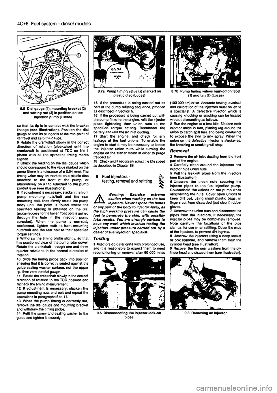
8.5 Dial gauge (1), mounting bracket (2) and setting rod (3) In position on the injection pump (Lucas)
so that Its tip Is In contact with the bracket linkage (see Illustration). Position the dial gauge so that its plunger is at the mid-point of its travel and zero the gauge. 6 Rotate the crankshaft slowly in the correct direction of rotation (clockwise) until the crankshaft is positioned at TDC on No 1 piston with ell the sprocket timing marks aligned. 7 Check the reading on the dial gauge which should correspond to the value marked on the pump (there is a tolerance of * 0.04 mm). The timing value may be marked on a plastic disc attached to the front of the pump, or alternatively on a tag attached to Ihe pump control lever (see illustrations). 8 If adjustment is necessary, slacken the front pump mounting nuts/bolt and the raar mounting bolt, then slowly rotate tne pump body until the point is found where the specified reading is obtained on the dial gauge (access to the lower front bolt is gained through the hole in the injection pump sprocket). When the pump Is correctly positioned, tighten both its front mounting nuta/bolt and the rear bolt to their specified torque settings. 9 Withdraw the timing probe slightly, so that it
8.7a Pump timing value (x) marked on plastic diso (Lucas)
15 If the procedure is being carried out as part of the pump refilling sequence, proceed as described in Section 5. 16 If the procedure is being carried out with the pump fitted to the engine, refit the injector pipes tightening their union nuts to the specified torque setting. Reconnect the battery and refit the air inlet ducting. 17 Start the engine, and check for any leakage at the fuel unions. To enable the engine to start it may be necessary to loosen tho injector union nuts while turning the engine on the starter motor in order to purge trapped air. 18 Check and If necessary adjust the Idle speed as described In Chapter 1B.
9 Fuel Injectors -testing, removal and refitting Sk ^
A
Warning: Exercise extreme caution when working on the fuel injectors. Never expose the hands or any part of the body to Injector spray, as the high working pressure can cause the fuel to pen ot rate the skin, with possibly fatal results. You are strongly advised to have any work which involves testing the injectors under pressure carried out by a dealer or fuel Injection specie list.
Testing 1 Injectors do deteriorate with prolonged uso, and it is reasonable to expect them to need reconditioning or renewal after 60 000 miles
8.7b Pump timing values marked on label (1) and tag (2) (Lucas)
(100 000 km) or so. Accurate testing, overhaul and calibration of the Injectors must be left to a specialist. A defective injector which Is causing knocking or smoking can be located without dismantling as follows. 2 Run the engine at a fast idle. Slacken each Injector union In turn, placing rag around the union to catch spilt fuel, and being careful not to exposa the skin to any spray. When tho union on the defective Injector is slackened, the knocking or smoking will stop.
Removal 3 Remove ihe air Inlet ducting from tho front part of the onglne. 4 Carefully clean around the Injectors and injector pipe union nuts. 5 Pull the leak-off pipes from the injectors (see illustration). 6 Unscrow the union nuts securing Ihe injector pipes to the fuel Injection pump. Counterhold the unions on the pump when unscrewing the nuts. Cover open unions lo keep dirt out, using small plastic bags, or fingers cut from discarded (but clean!) rubber gloves. 7 Unscrew the union nuts and disconnect the pipes from the ln|ectors, If necessary, the Injector pipes may be completely removed-Note carefully the locations of the pipe clamps, for use when refitting. Cover tho onds ot (he injectors, to prevent dirt ingress. 8 Unscrew the injectors using a deep socket or box spanner, and remove Ihem from the cylinder head (see Illustration). 9 Recover the tire seal washers from the cy-linder head and discard them (see illustration).
9.5 Disconnecting the Injector leak-off pipes 9.8 Removing an injector
Page 143 of 225
Fuel system - diesel models 4C*3
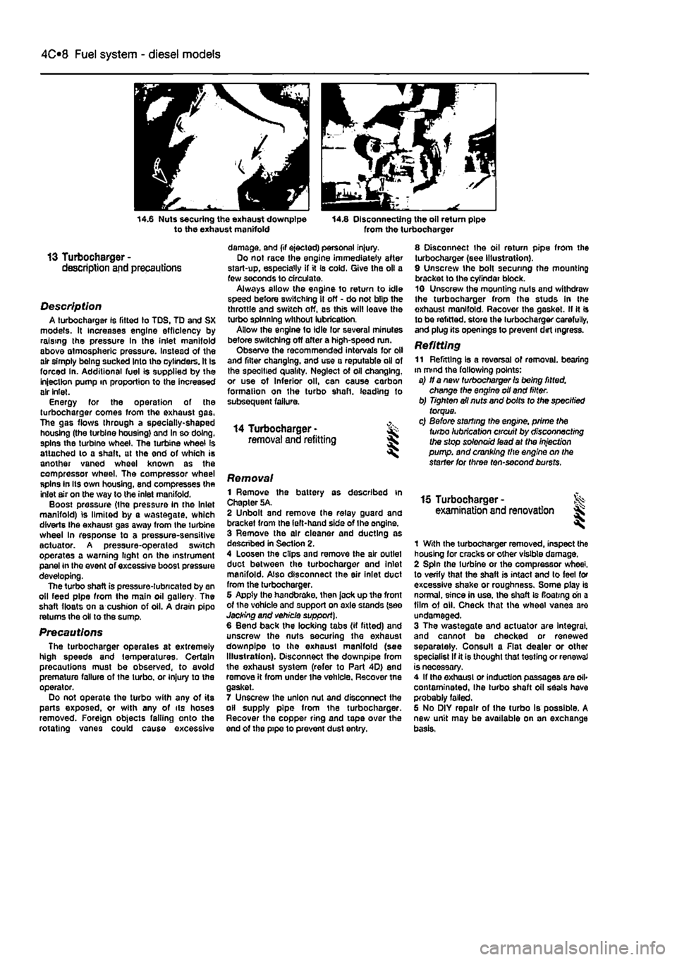
14.6 Nuts securing the exhaust downpipe to the exhaust manifold 14.8 Disconnecting the oil return pipe from tho turbocharger
13 Turbocharger -description and precautions
Description A turbocharger 1$ fitted to TDS, TD and SX models. It increases engine efficiency by raising the pressure In the inlet manifold above atmospheric pressure. Instead of the air simply being sucked Into the cylinders. It Is forced in. Additional fuel is supplied by the injection pump in proportion to the increased air inlet. Energy for the operation of the turbocharger comes from the exhaust gas. The gas flows through a specially-shaped housing (the turbine housing) and In so doing, spins the turbine wheel. The turbine wheel is attached lo a shaft, at the end of which is another vaned wheel known as the compressor wheel, The compressor wheel spins in Its own housing, snd compresses the inlet air on the way to the inlet manifold. Boost pressure (the pressure in the Inlet manifold) is limited by a wastegate, which diverts Ihe exhaust gas away from the turbine wheel In response to a pressure-sensitive actuator. A pressure-operaled switch operates a warning light on the instrument panel in the event of excessive boost pressure developing. The turbo shaft is pressure-lubricated by an oil feed pipe from the main oil gallery The shaft floats on a cushion of oil. A drain pipo returns the oil to the sump.
Precautions The turbocharger operates at extremely high speeds and temperatures. Certain precautions must be observed, to avoid premature failure of the turbo, or injury to the operator. Do not operate the turbo with any of its parts exposed, or with any of ils hoses removed. Foreign objects falling onto the rotating vanes could cause excessive
damage, and (if ejected) personal injury. Do not race the engine immediately after start-up, especially if it Is cold. Give the oil a few seconds lo circulate. Always allow the engine to return to idle speed before switching il off - do not blip the throttle and switch off, as this will leave the turbo spinning without lubrication. Allow the engine to idle lor several minutes before switching off after a high-speed run. Observe the recommended intervals for oil and filter changing, and use a reputable oil of the specified quality. Neglect of oil changing, or use of Inferior oil, can cause carbon formation on the turbo shaft, leading to subsequent failure.
14 Turbocharger -removal and refitting
8 Disconnect the oil return pipe from the turbocharger (see Illustration). 9 Unscrew the bolt securing the mounting bracket to the cyfindar block. 10 Unscrew the mounting nuts and withdraw the turbocharger from the studs in Ihe exhaust manifold. Recover the gasket. II It Is to be refitted, store the turbocharger carefully, and plug its openings to prevent dirt ingress.
Refitting 11 Refitting Is a reversal of removal, bearing in mind the fallowing points: a) if a new turbocharger Is being fitted, change the engine oil and filter. b) Tighten ail nuts and bolts to the specified torque. c) Before starting the engine, prime the turbo lubrication circuit by disconnecting the stop solenoid iead at the injection pump, and cranking the engine on the starter for three ten-second bursts.
Removal 1 Remove the battery as described in Chapter 5A. 2 Unbolt and remove the relay guard and bracket from the left-hand side of Ihe engine. 3 Remove the air cleaner and ducting as descnbed in Section 2. 4 Loosen the clips and remove the air outlet duct between tho turbocharger and inlet manifold. Also disconnect the air inlet duct from the turbocharger. 6 Appty the handbrake, then jack up tho front of the vohicle and support on axle stands (see Jacking and vehicle support). 6 Bend back the locking tabs (if fitted) and unscrew the nuts securing the exhaust downpipe lo the exhaust manifold (see Illustration). Disconnect the downpipe from the exhaust system (refer to Part 4D) end remove it from under the vehicle. Recover tne gasket. 7 Unscrew ihe union nut and disconnect the oil supply pipe from the turbocharger. Recover the copper ring and tape over the end of the pipe 10 prevent dust entry.
15 Turbocharger -examination and renovation l
1 With the turbocharger removed, inspect the housing for cracks or other visible damage. 2 Spin the turbine or the compressor wheel, to verify that the shaft is intact and to feel for excessive shake or roughness. Some play is normal, since in use, the shaft is floating on a film of oil. Check that the wheel vanes are undamaged. 3 The wastegate and actuator are Integral, and cannot be checked or renewed separately. Consul! a Flat dealer or other specialist If it is thought that testing or renewal is necessary. 4 If tho exhaust or induction passages are ail* contaminated, Ihe turbo shaft oil seals have probably failed. 6 No DIY repair of the turbo is possible. A new unit may be available on an exchange basis,
Page 154 of 225
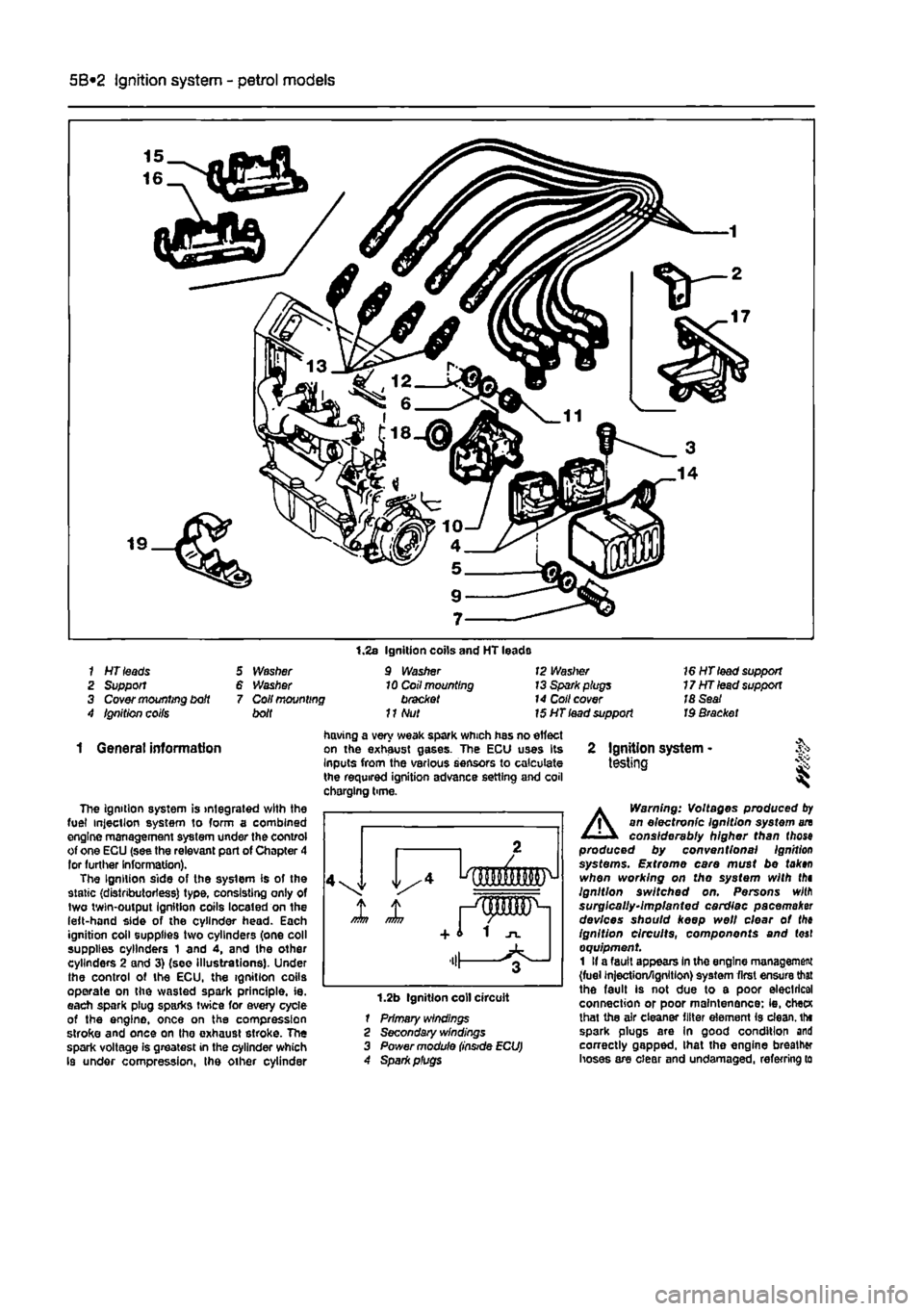
5B*2 Ignition system - petrol models
1 HT leads 2 Support 3 Cover mounting bdt 4 Ignition coifs
5 Washer 6 Washer 7 Coil mounting bolt
1.2s Ignition coils and HT leads 9 Washer 10 Coil mounting bracket
11
Nut
12 Waslrer 13 Spark plugs 14 Coll cover 15 HT lead support
16 HT lead support 17HTlead support 18 Seat Id Bracket
1 General information
The ignition system is integrated with the fuel injection system to form a combined engine management system under the control of one ECU (see the relevant part of Chapter 4 lor further Information). The Ignition side of the system is of the static (distributorless) type, consisting only of two twin-output Ignition coils located on the left-hand side of the cylinder head. Each ignition coil supplies two cylinders (one coll supplies cylinders 1 and 4, and the other cylinders 2 and 3) (see Illustrations). Under the control of the ECU, the ignition coils operate on the wasted spark principle, ie. each spark plug sparks twice for every cycle of the engine, once on the compression stroke and once on tho exhaust stroke. The spark voltage is greatest in the cylinder which Is under compression, the other cylinder
having a very weak spark which has no effect on the exhaust gases. The ECU uses Its Inputs from the various sensors to calculate the required ignition advance setting and coil chorging time.
1.2b Ignition coll circuit 1 Primary windings 2 Secondary windings 3 Power module
2 Ignition system -testing i
A
Warning: Voltages produced
by
an electronic Ignition system an considerably higher than (hose produced by conventional Ignition systems. Extreme care must be tak»n when working on tho system with thi Ignition switched on. Persons wilfl surgically-implanted cardiac pacemaker devices should keep well clear ot the ignition circuits, components and (oaf equipment 1 If a fault appears In the engine management (fuel injection/ignition) system first ensure that the fault is not due to a poor electrical connection or poor maintenance: ie, checK lhat the air cleaner filter element is clean, tht spark plugs are In good condition and correctly gapped, lhat the engine breather hoses are clear and undamaged, referring to
Page 159 of 225
6*2 Clutch
3 Clutch cable -removal and refitting
Note: This procedure applies to models fitted with a cabfe-opemted dutch
release mechanism.
Removal 1 Remove the battery and tray as described In Chapter SA. If necessary, also remove the Inlet air ducting for Improved access as described In the relevant part of Chapter 4. 2 Unscrew the adjustment locknut and adjuster nut from the end of the cable fitting, (hen release the inner and outer cables from the transmission housing. Note the position of the damper biock. 3 Working Inside the vehicle, unhook the inner cable from the top of the clutch pedaL 4 Returning to the engine compartment, unscrew the nuts securing the outer cable to the bulkhead, then withdraw the cable assembly from the engine compartment. Refitting 5 Apply a smear of multi-purpose grease to the cable end fittings, then pass the cable through the bulkhead. Refit and tighten the nuts. 6 Inside the vehicle hook the inner cable onto the top of the clutch pedal. 7 in the engine compartment, attach the outer cable to the transmission housing and refit the damper block and nuts lo Ihe inner cable end. fi Adjust the cable as described in Section 2. 9 Refit the air ducting and battery with reference to Chapters 4 and 5A
4 Clutch hydraulic system -
i
Note: This procedure applies to models fitted with the hydraulicalty-operated clutch release mechanism.
A
Warning: Hydraulic fluid Is poisonous; thoroughly wash off spllfs from bare skin without delay. Seek Immediate medical advice If any fluid is swallowed or gets into the eyes. Certain types of hydraulic fluid are Inflammable and may ignite when brought into contact with hot components; when servicing any hydraulic system, It is safest to assume that the fluid IS Inflammable, and to take precautions against the risk of fire as though ft were petrof that was being handled. Hydraulic fluid Is an effective paint stripper and will also attack many plastics. If spillage occurs onto painted bodywork or fittings, ft should be washed off Immediately, using copious quantities of fresh water. It Is also hygroscopic - It can absorb moisture from the air, which then renders it useless. Old fluid may have
suffered contamination, and should never be re-used. When topping-up or renewing tho fluid, always use tha recommended grade, and ensure that It comes from a new seated container. General information 1 Whenever the clutch hydraulic lines are disconnected for service or repair, a certain amount of air will enter the system. The presence of air In any hydraulic system will Introduce a degree of elasticity, and in the clutch system this will translate into poor pedal feel and reduced travel, leading to inefficient gear changes and even clutch system failure. For this reason, the hydraulic lines must be sealed using hose clamps before any work la carried out and then on completion, topped up and bled to remove any air bubbles. 2 To seal off Ihe hydraulic supply to tha clutch slave cylinder, fit a proprietary brake hose clamp to the flexible section of the hose located over the transmission and tighten it securely. It will be necessary to remove the battery and battery tray to access the hose. 3 The most effective way of bleeding the clutch hydraulic system is to use a pressure brake bleeding kit. These are readily available in motor accessories shops and are extremely effective: the following sub-section describes bleeding the clutch system using such a kit. The alternative method is to bleed the system by depressing tho clutch pedal • refer to Chapter 9. Section 11, for details of this method.
Bleeding 4 Remove the protective cap from Ihe bleed nipple on the slave cylinder. Access can be improved by removing the battery and tray with reference to Chapter 5A. 5 Fit a ring spanner over the bleed nipple head, but do not slacken it at this point. Connect a length of dear plastic hose over the nipple and insert the other end into a clean container. Pour hydraulic fluid into the container, such that the end of the hose is covered. 6 Following the manufacturer's instructions, pour hydraulic fluid into the bleeding kit vessel 7 Unscrew the vehicle's fluid reservoir cap, then connect Ihe bleeding kit fluid supply hose to the reservoir. 8 Connect the pressure hose to a supply of compressed air - a spare tyre is a convenient source. Caution: Check that the pressure In the tyre does not exceed the maximum supply pressure quoted by the kit manufacturer, let soma sir escape to reduce the pressure, if necessary. Gently open the air valve and allow the air and fluid pressures to equalise. Check that there ere no teaks before proceeding. 9 Using the spanner, slacken the bleed pipe nipple until fluid and air bubbles can be seen to flow through the tube, into the container.
Maintain a steady flow until the emerging fluid la free of air bubbles; keep a watchful eye on the level of fluid in the bleeding kit vessel and the vehicle's fluid reservoir • if it Is allowed to drop too low, air may be forced into the system, defeating the object of the exercise. To refill the vessel, turn off the compressed air supply, remove the lid and pour In en appropriate quantity of clean fluid from a new container - do not re-use the fluid collected in the receiving container. Repeat as necessary until the ejected fluid is bubble-free. 10 On completion, pump the olutch pedal several times to assess its feel and travel. If firm, constant pedal resistance is not felt throughout the pedal stroke, it i6 probable that air Is still present in the system - repeat the bleeding procedure untii the pedal feel is restored. 11 Depressurise the bleeding kit and remove it from the vehicle. At this point, the fluid reservoir may be over-full; the excess should be removed using a clean pipette to reduce the level to the MAX mark. 12 Tighten the bleed pipe nipple using the spanner and remove the receiving container. Refit the protective cap. 13 On completion, assess the feel of the clutch pedal; if it exhibits any sponginess or looseness, further bleeding may be required. 14 Where removed, refit the battery and tray. 15 Finally, road test the vehicle and check the operation of the clutch system whilst changing up and down through the gsar9. whilst pulling away from a standstill and from a hill start.
5 Clutch master cylinder - & removal
and
refitting 5 S Note: This procedure applies to models
fitted
with the hydraulically-operated dutch
release
mechanism. Note: Refer to the warning at Ihe beginning
of
Section 4 regarding the hazards of
working
with hydraulic fluid.
Removal 1 Disconnect the battery negative terminal (refer lo Disconnecting the battery in the Reference Section of this manual). 2 Remove the air cleaner and air ducting as described in the relevant Part of Chapter 4. 3 For improved access on petrol engine models, remove the alternator as described In Chapter 5A. 4 Fit a brake hose clamp to the hose between the hydraulic fluid reservoir and the clutch master cylinder. Alternatively syphon ail the fluid from the reservoir. 5 Disconnect the fluid supply hose at the master cylinder, then unscrew the union nut and disconnect the hydraulic pipe from the cylinder outlet. Be prepared for some fluid loss by placing some rags beneath the master cylinder.