Trem FIAT PUNTO 1998 176 / 1.G User Guide
[x] Cancel search | Manufacturer: FIAT, Model Year: 1998, Model line: PUNTO, Model: FIAT PUNTO 1998 176 / 1.GPages: 225, PDF Size: 18.54 MB
Page 165 of 225

7A«4 Manual transmission
33 Remove lha air cleaner front section and air ducting with reference to Chapter 4C. Also disconnect the injection pump vacuum pipe from the clips on the left-hand end of the cylinder head. This work is necessary in order to fit the engine hoist 34 Support the weight of the engine using a hoist attached to the engine lifting eyes, or alternatively use a trolley Jack and block of wood beneath the engine. 35 Unscrew the nuts securing the downpipe to the exhaust manifold, then lower it and support on an axle stand. Recover the gasket. 36 Unscrew the starter motor mounting bolts and support the starter motor to one side. 37 Disconnect the wiring from the reversing light switch on the front of the transmission. 38 Unscrew the nut and disconnect the earth cable from its stud. 39 Trace the wiring back from the electronic speedometer sensor and disconnect the connector located on the left-hand side ot the engine. If a mechanical speedometer Is fitted unscrew the knurled collar and disconnect the cabte from the transmission. 40 Unbolt and remove the transmission lower cover. 41 Using an Allen key unscrew the bolts securing the inner end of the left-hand driveshaft to the transmission flange. Remove the bolts and recover the spacer plates. Support the driveshaft on an axle stand. 42 Unscrew and remove the bolts securing the left-hand swivel hub assembly to the front suspension strut, then separate the components and support the swivel hub on an axle stand. 43 Move the swrvel hub assembly outwards and support the driveshaft away from Ihe transmission. 44 Using an Allen key unscrew the bolts securing the Inner end of the right-hand driveshaft to the intermediate shaft flange. Remove the bolts and recover the spacer plates. Support the driveshaft on an axle stand. 45 Remove the intermediate driveshaft with reference to Chapter 8. 46 Working beneath the vehicle, unscrew the bolts securing the rear engine mounting to the underbody then unscrew the bolts securing the mounting to the transmission and withdraw the mounting assembly from under the vehicle.
47 Unscrew the bolts securing the left-hand engine/transmission mounting to the body then unscrew Ihe bolts from the transmission and remove the mounting. 48 Support the weight of the transmission on a trolley jack then unscrew the remaining nut and bolts from the bellhousing and pull the transmission away from the engine.
A
Warning: Support the trans-mission to ensure that It remains steady o/i the jack head. Keep the transmission level until the Input shaft
1$
fully withdrawn from the clutch friction plate.
Refitting 48 Refitting is a reversal of the removal procedure, but note the following points. a) Appiy a smear* of high-meiting-point grease to the clutch friction piate splines; take care to avoid contaminating the friction surfaces. b) Tighten all bolts to the specified torque. c) Fit new clips to secure the driveshaft gaiters to the transmission output shafts. d) Adjust the clutch cable (where applicable) as described In Chapter 6.
4 Manual transmission overhaul -general Infomtatlon
Overhauling a manual transmission is a difficult and Involved Job for the DIY home mechanic. In addition to dismantling and reassembling many small parts, clearances must be precisely measured and, if necessary, changed by selecting shims and spacers. Internal transmission components are also often difficult to obtain, and in many Instances, extremely expensive. Because of this, If the transmission develops a fault or becomes noisy. Ihe best course of action is to have the unit overhauled by a specialist repairer, or to obtain an exchange reconditioned unit. Nevertheless, it is not impossible for the more experienced mechanic to overhaul the transmission, provided the special tools are available, and the Job is done in a deliberate step-by-step manner, so that nothing is overlooked.
The tools necessary for an overhaul include internal and external clrclip pliers, bearing pullers, a slide hammer, a sat of pin punches, a dial test Indicator, and possibly a hydraulic press. In addition, a large, sturdy workbench 8od a vice will be required. During dismantling o1 the transmission, make careful notes of how each component
1$
fitted, to make reassembly easier and more accurate. Before dismantling the transmission, it will help if you have some idea what area is malfunctioning. Certain problems can be closely related to specific areas In the transmission, which can make component examination and replacement easier. Refer to the Fault Finding Section at the end of this manual for more Information.
5 Reversing light switch -testing, removal and refitting ||
Testing 1 The reversing light circuit is controlled by a plunger-type switch screwed into the front of the transmission casing. If a fault develops, first ensure that Ihe circuit fuse has not blown. 2 To test the switch, disconnect the wiring connector, and use a multimeter (set to the resistance function) or a battery-and-bulb test circuit to check that there is continuity between the switch terminals only when reverse gear is selected. If this is not the case, and there are no obvious breaks or other damage to the wires, the switch is faulty, and must be renewed.
Removal 3 Access to the reversing light switch Is best achieved from under the vehicle. Apply the handbrake then jack up Ihe front of the vehicle and support on axle stands (see Jacking and vehicle support). 4 Disconnect the wiring connector, then unscrew It from the transmission casing.
Refitting 5 Refit the switch and tighten securely. 6 Reconnect the wiring then lower the vehicle to the ground.
Page 173 of 225

8*2 Driveshafts
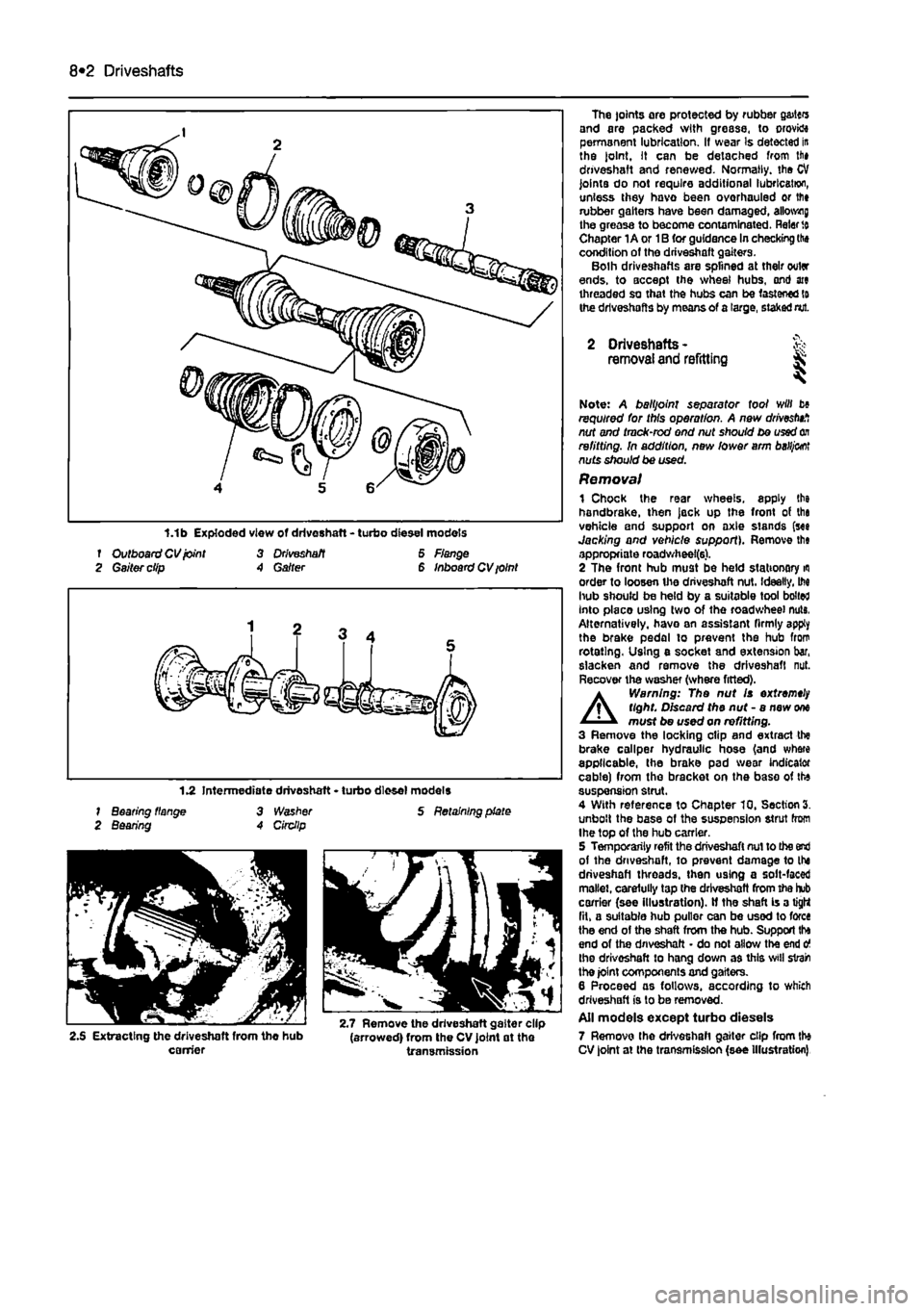
f Outboard CV joint 3 Driveshaft 6 Flange 2 Gaiter clip A Garter 6 Inboard CV ioint
1.2 Intermediate driveshaft • turbo diesel models 1 Bearing flange 3 Washer S Retaining plate 2 Bearing A Circllp
2.S Extracting the driveshaft from the hub (arrowed) from the CV joint at the carrier transmission
The joints are protected by rubber g&itcrs and are packed with grease, to orovktt permanent lubrication. If wear Is detected in the joint. It can be detached from lii» driveshaft and renewed. Normally, the CV joints do not require additional lubrication, unless they havo been overhauled or lfi» rubber gaiters have been damaged, allotting the greasa to become contaminated. Rater
to
Chapter 1A or 1B for guidance In checking the condition of the driveshaft gaiters. Bolh driveshafts are splined at their outer ends, to accept the wheel hubs, ond ate threaded so that the hubs can be fastened to the driveshafts by means of a large, staked nut.
2 Driveshafts -removal and refitting & ^
Note: A balljoint separator tool will b» required for this operation. A new drivestnf, nut and tmck-rod end nut should be used
on
refitting. In addition, new lower arm
baHj&ot
nuts should be used. Removal 1 Chock the rear wheels, apply the handbrake, then jack up the front of tha vehicle and support on axle stands (see Jacking and vehicle support). Remove th« appropriate roadwheel(6). 2 The front hub must be held stationary
m
order to loosen the driveshaft nut. Ideally, M hub should be held by a suitable tool bolted Into placo using two of the roadwheel nuts, Alternatively, havo an assistant firmly apply the brake pedal to prevent the hub from rotating. Using e socket and extension bar, slacken and remove the driveshaft nut. Recover the washer (where fitted).
A
Warning: The nut Is extremely tight. Discard the nut - a new
one
must be used on refitting. 3 Remove the locking clip and extract the brake caliper hydraulic hose (and where applicable, the brake pad wear indicator cable) from the bracket on the base of the suspension strut. 4 With reference to Chapter 10, Section 3. unbolt the base of the suspension strut from Ihe top of the hub carrier. 5 Temporarily refit the driveshaft nut to the end of the driveshaft, to prevent damage to the driveshaft threads, then using a solt-faced mallet, carefully tap the driveshaft from the hub carrier (see illustration). If the shaft is a tight fit, a suitable hub puller can be used to force the end of the shaft from the hub. Support tha end of the driveshaft • do not allow the end o the driveshaft to hang down as this svill strain the joint components and gaiters. 6 Proceed as follows, according to which driveshaft is to be removed. All models except turbo diesels 7 Remove the driveshaft gaiter clip from the CV joint at the transmission (see Illustration)
Page 216 of 225

Body electrical systems 12*3
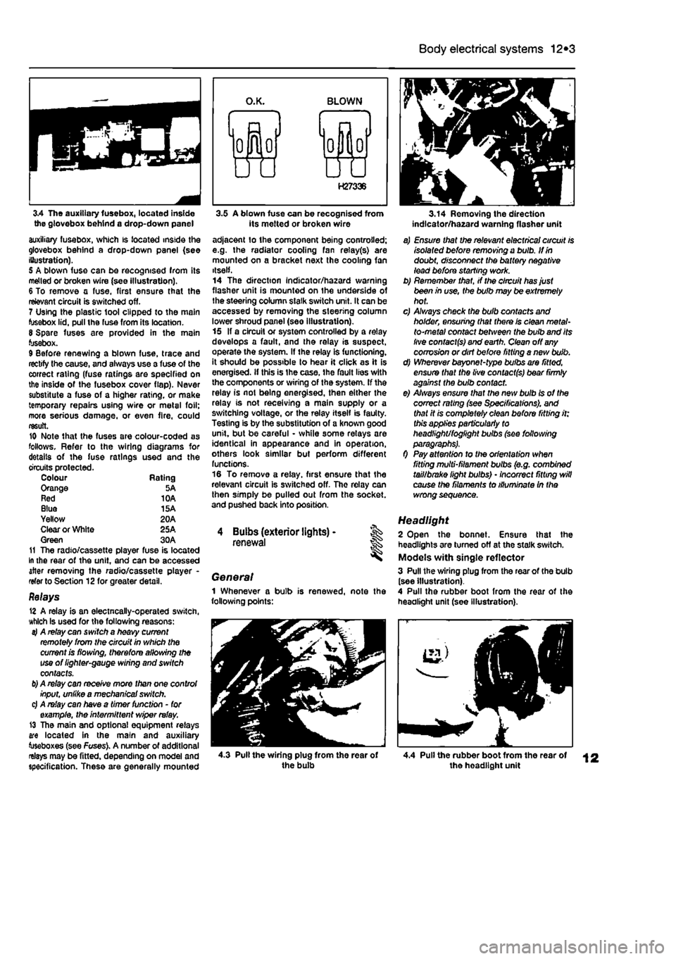
3.4 The auxiliary fusebox, located inside the glovebox behind a drop-down panel auxiliary fusebox, which is located inside the glovebox behind a drop-down panel (see Illustration). 5 A blown fuse can be recognised from its melted or broken wire (see illustration). 6 To remove a fuse, first ensure that the relevant circuit is switched off. 7 Using the plastic tool clipped to the main fusebox lid, pull the fuse from its location. 8 Spare fuses are provided in the main fusebox. 9 Before renewing a blown fuse, trace and rectify the cause, and always use a fuse of the correct rating (fuse ratings are specified on the inside of the fusebox cover flap). Never substitute a fuse of a higher rating, or make temporary repairs using wire or metal foil; more serious damage, or even fire, could result. 10 Note that the fuses are colour-coded as follows. Refer to the wiring diagrams for details of the fuse ratings used and the circuits protected. Colour Rating Orange 5A Red 10A Blue 15A Yellow 20A Clear or White 25A Green 30A 11 The radio/cassette player fuse is located In the rear of the unit, and can be accessed after removing the radio/cassette player -refer to Section 12for greater detail.
Relays 12 A relay is an electncally-operated switch, which Is used for the following reasons: 4 A relay can switch a heavy current remotely from the circuit in which the current is flowing, therefore allowing the use of lighter-gauge wiring and switch contacts.
b)
A relay can receive more than one control input, unlike a mechanical switch. c) A relay can have a timer function - for example, the intermittent wiper relay. 13 The main and optional equipment relays are located in the main and auxiliary toseboxes (see Fuses). A number of additional relays may be fitted, depending on model and specification. These are generally mounted
3.5 A blown fuse can be recognised from its melted or broken wire adjacent lo the component being controlled; e.g. the radiator cooling fan relay(s) are mounted on a bracket next the cooling fan itself. 14 The direction Indicator/hazard warning flasher unit is mounted on the underside of the steering column slalk switch unit. It can be accessed by removing the steering column lower shroud panel (see illustration). 15 If a circuit or system controlled by a relay develops a fault, and the relay is suspect, operate the system. If the relay is functioning, it should be possible to hear it click as it is energised, if this is Ihe case, the fault lies with the components or wiring of the system. If the relay is not being energised, then either the relay is not receiving a main supply or a switching voltage, or the relay itself is faulty. Testing is by the substitution of a known good unit, but be careful - while some relays are identical in appearance and in operation, others look similar but perform different functions. 16 To remove a relay, first ensure that the relevant circuit is switched off. The relay can then simply be pulled out from the socket, and pushed back into position.
4 Buibs (exterior lights) -renewal
General 1 Whenever a bulb is renewed, note the following points:
3.14 Removing the direction indlcator/ha2ard warning flasher unit
a) Ensure that the relevant electrical circuit is isolated before removing a bulb. If in doubt, disconnect the battery negative lead before starting work. b) Remember that, if the circuit has just been in use, the bulb may be extremely hot. c) A/ways check the bulb contacts and holder, ensuring that there is clean metal-to-metal contact between the bulb and its live contacts) and earth. Clean off
any
corrosion or dirt before fitting a nevt bulb. d) Wherever bayonet-type bulbs are fitted, ensure that the live contacts) bear firmly against the bulb contact. e) Always ensure that the new bulb is of the correct rating (see Specifications), and that it is completely clean before fitting it; this applies particularly to headlight/foglight bulbs (see following
0 Pay attention to the orientation when fitting multi-filament bulbs (e.g. combined tail/brake light bulbs) • incorrect fitting will cause the filaments to illuminate In the wrong sequence.
Headlight 2 Open the bonnet. Ensure that the headlights are turned off at the stalk switch. Models with single reflector 3 Pull the wiring plug from the rear of the bulb (see illustration). 4 Pull the rubber boot from the rear of the headlight unit (see Illustration).
4.3 Pull the wiring plug from the rear of the bulb 4.4 Pull the rubber boot from the rear of the headlight unit
Page 219 of 225

12*6 Body electrical systems
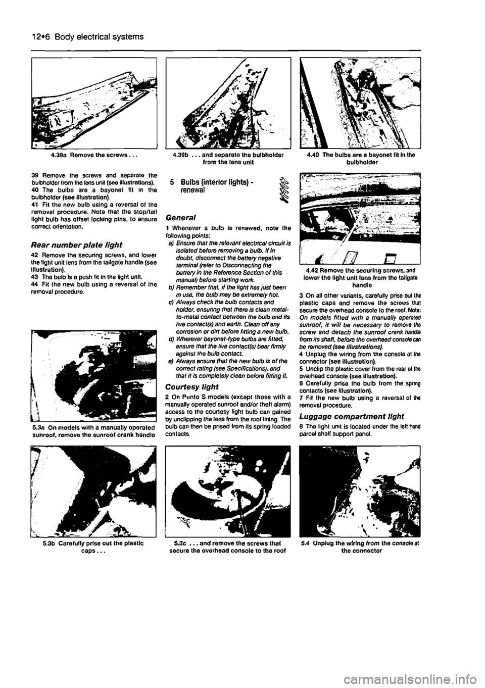
4.39a Remove the screws...
39 Remove the screws and separate the bulbholder from the lens unit (see Illustrations). 40 The bulbs are a bayonet (it in the bulbholder (s&e Illustration), 41 Fit the new bulb using a rovorsal of the removal procedure. Note that the stop/tall light bulb has offset locking pins, to ensure correct orientation.
Rear number plate light 42 Remove the securing screws, and lower the light unit lens from the tailgate handle (see Illustration), 43 The bulb Is a push fit In the light unit. 44 Fit the new bulb using a reversal of the removal procedure.
5.3a On models with a manually oporated sunroof, remove the sunroof crank handle
5.3b Carefully prise out the pfestic caps...
from the lens unit
5 Bulbs (interior lights) -renewal
General 1 Whenever a bulb is renewed, note Ihe following points: a) Ensure that the relevant electrical circuit is Isolated before removing a bulb. If
In
doubt, disconnect the battery negative terminal (refer to Disconnecting the battery In the Reference Section of this manual) before starting work. b) Remember that, if the light has just been in use, the bulb may be extremely hot. c) Always check the bulb contacts and holder, ensuring that there is clean metal-to-metal contact between the bulb and its live contacts) and earth, dean off any corrosion or dirt before fitting a new bulb. d) Wherever bayonet-type bulbs are fitted, ensure that the live contact(s) bear (irmly against the bulb contact. e) Always ensure that the new bulb is of the correct rating (see Specifications), and that it Is completely clean before fitting it.
Courtesy light 2 On Punto S models (except those with a manually operated sunroof end/or theft alarm) access to the courtesy light bulb can gained by unclipping the lens from the roof lining. The bulb can then be prised from its spring loaded contacts.
5.3c ... and remove the screws that secure the overhead console to the roof
buibhoidai
/ ' fl B 4.42 Remove the securing screws, and lower the light unit lens from the tailgate handle 3 On all other variants, carefully prise out the plastic caps and remove the screws that secure the overhead console lo the roof. Note: On models fitted with a manually operator sunroof, it will be necessary to remove
the
screw and detach the sunroof crank
handle
from its shaft, before the overhead console can be removed (see illustrations). A Unplug Ihe wiring from the console at the connector (see illustration). 5 Unciip the plastic cover from the rear ol the overhead console (see illustration). 6 Carefully prise the bulb from the spring contacts (see Illustration). 7 Fit the new bulb using a reversal of the removal procedure.
Luggage compartment light 8 The light unit is located under 1he left hand parcel shelf support panel.
5.4 Unplug Ihe wiring from (he console at the connector