blade FIAT PUNTO 1998 176 / 1.G Workshop Manual
[x] Cancel search | Manufacturer: FIAT, Model Year: 1998, Model line: PUNTO, Model: FIAT PUNTO 1998 176 / 1.GPages: 225, PDF Size: 18.54 MB
Page 3 of 225
Contents
LIVING WITH YOUR FIAT PUNTO
Introduction to the Rat Punto Page 0-4 Safety lirstl Page 0*5
Roadside repairs If your car won't start Page 0*6 Jump starting Page 0*7 Wheel changing Page 0«8 Identifying teaks Page 0*9 Towing Page 0*9
Weekly checks Introduction Page 0*10 Underbonnet check points Page 0»10 Engine oil level Page 0*12 Coolant level Page 0*12 Brake fluid level Page 0*13 Power steering fluid level Page 0"13 Tyre condition and pressure Page 0*14 Automatic transmission fluid level Page 0«1S Screen washer fluid level Page 0«1S Wiper blades Page 0*15 Battery Page 0*16 Electrical systems Page 0-16
Lubricants and fluids Page 0*17
Tyre pressures Page 0*18
MAINTENANCE
Routine maintenance and servicing Rat Punto petrol models Page 1A«1 Servicing specifications Page 1A«2 Maintenance schedule Page 1A«3 Maintenance procedures Page 1A«6 Fiat Punto diesei models Page 1B-1 Servicing specifications Page 1B«2 Maintenance schedule Page 1B«3 Maintenance procedures Page 1B«5
expert22 fl/ia http://rutracker.org
Page 16 of 225
Weekly checks 015
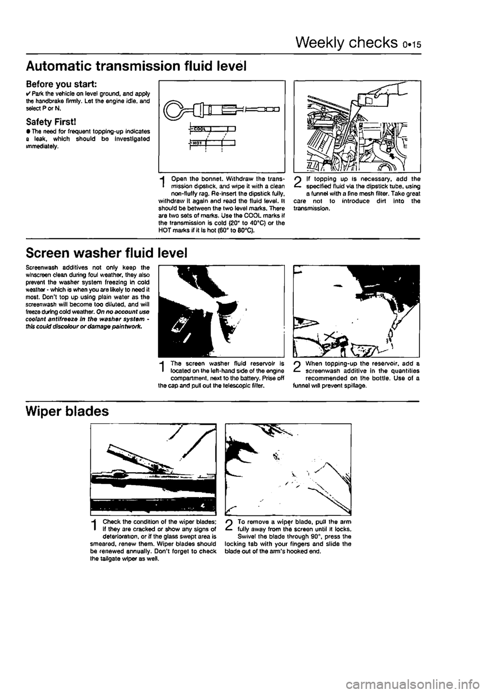
Automatic transmission fluid level
Before you start: • Park the vohicle on level ground, and apply the handbrake firmly. Let the engine idle, and select P or N.
Safety First! • The need for frequent topping-up indicates a leak, which should bo Investigated immediately.
I
Open the bonnet. Withdraw the trans-mission dipstick, and wipe it with a clean non-fluffy rag. Re-Insert the dipstick fully, withdraw it again and read the fluid level. II should be between (he two level marks. There are two sets of marks. Use the COOL marks if the transmission is cold (20" to 40°C) or the HOT marks if it Is hot (60" to 809C).
2
If topping up fs necessary, add the specified fluid via the dipstick tube, using a funnel with a fine mesh filter. Take great care nol to introduce dirt into the transmission.
Screen washer fluid level
Screenwash additives not only keep the wlnscreen clean during foul weather, they also prevent the washer system freezing kn cold weather • which is when you are likely to need it most. Don't top up using plain water as the screenwash will become too diluted, and will freeze during cold weather. On no account use coolant antifreeze In the washer system • this could discolour or damage paintwork.
3H
m
I
The screen washer fluid reservoir is located on the left-hand side of the engine compartment, next to the battery. Prise off the cap and pull out the telescopic filler.
2
When topping-up the reservoir, add a screenwash additive In the quantities recommended on the bottle. Use of a funnel wilt prevent spillage.
Wiper blades
1
Check the condition of the wiper blades; if they are cracked or show any signs of deterioration, or if the glass swept area is smeared, renew them. Wiper blades should be renewed annually. Don't forget to check the tailgate wiper as well.
2
To remove a wiper blade, pull the arm fully away from the screen until It locks. Swivel the blade through 90", press the locking tab with your fingers and slide the blade out of the arm's hooked end.
Page 29 of 225
ia.io Every 20 000 miles - petrol models
the front of the car and support It securely on axle stands (see Jacking and vehicle support}. 4 Remove the nght-hand front wheel. 5 Remove the inner cover from under the right-hand wheeiarch for access to the right-hand side of the engine. 0 Using a socket on the crankshaft sprocket boll, rotate the crankshaft so that the full length of the auxiliary drlvebelt(s) can be examined. Look for cracks, splitting and fraying on the surface of the belt: check also for signs of glazing (shiny patches) and separation of the belt plies. If damage or wear Is visible, the relevant belt should be renewed. 7 If the condition of the belt Is satisfactory, check Ihe drivebeit tension as described below.
Renewal
Alternator drivebeit Note: On certain models with power steering but without air conditioning, it will be necessary to remove the power steering pump drivebeit ffrst, as described below. 8 Where fitted, undo the bolts and remove the belt guard from the alternator. 9 Loosen the pivot and adjustment bolts then swivel the alternator towards the engine and slip off the drivebeit. 10 Unbolt and remove the crankshaft sensor from Ihe front of the engine (refer to Chapter 4A. Section 5, if necessary). 11 Remove the drivebeit from the engine. 12 When renewing a drivebeit. ensure that the correct type is used. Fit the belt around the two pulleys then swivel the alternator outwaids to take up any slack in the betL Adjust the tension correctly as described below. Power steering pump drivebeit 13 Slacken the bolts securing the power steering pump to the mounting bracket. 14 Slacken the adjusting bolt locknut and turn the adjusting boit until all the tension is removed from the drivebeit. 15 Undo the bolts and remove the pultey guard from the power steering pump then slip the drivebeit off (he pulleys. 18 Ensuring that the correct type of drivebeit is used, fit the belt around the pulleys and turn the adjusting bolt to just take up the slack in the belt. Adjust the tension correctly as described below. Air conditioning compressor drivebeit 17 Remove the alternator and power steering pump dnvebelts as described previously. 18 Slacken the bolts securing the compressor to the mounting bracket. 19 Slacken the adjusting bolt locknut and turn the adjusting bolt until alt the tension is removed from the drivebeit, then slip the belt off the pulleys. 20 Ensuring lhat the correct type of drivebeit is used, fit the belt around the pulleys and turn the adjusting bolt to just take up the slack In the belt. Adjust the tension correctly as described below.
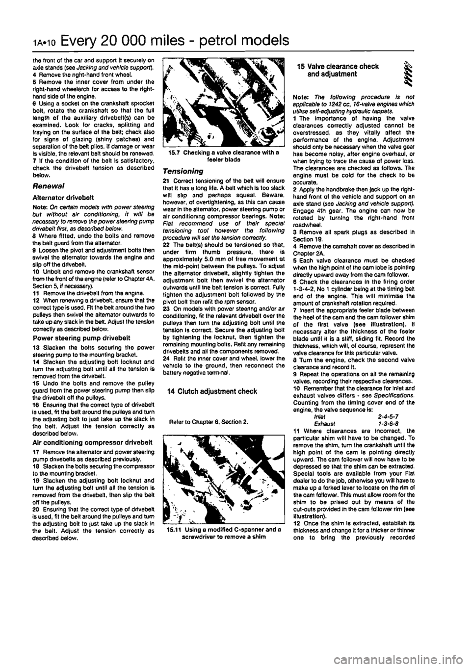
15.7 Checking a valve clearance with a feeler blade
Tensioning 21 Correct tensioning of the belt will ensure that it has a long life. A belt which Is too slack will slip and perhaps squeal. Beware, however, of overtightening, as this can cause wear in the alternator, power steering pump or air conditioning compressor bearings. Note: Fiat recommend use of their special tensioning tool however the fallowing procedure will set the tension correctly. 22 The belt(s) should be tensioned so that, under firm thumb pressure, there is approximately 5.0 mm of free movement at the mid-point between the pulleys. To adjust the alternator drivebeit, slightly tighten the adjustment bolt then swivel the alternator outwards until tne beft tension Is correct. Fully tighten the adjustment bolt followed by the pivot bolt then refit the rpm sensor. 23 On models with power steering and/or air conditioning, fit the relevant drivebeit over the pulleys then turn the adjusting bolt until the tension is correct. Secure the adjusting bolt by tightening Ihe locknut, then tighten the remaining mounting bolts. Refit any remaining dnvebelts and all the components removed. 24 Refit the inner cover and wheel, lower the vehicle to the ground, then reconnect the battery negative terminal,
14 Clutch adjustment check
Refer to Chapter 8. Section 2.
15.11 Using a modified C-spanner and e screwdriver to remove a shim
15 Valve clearance check ^ and adjustment S
Note: The following procedure Is not applicable to 1242 cc,
16-vatve
engines which utilise self-adjusting hydraulic tappets. 1 The importance of having the valve clearances correctly adjusted cannot be overstressed, as they vitally affect the performance of the engine. Adjustment should only be necessary when the valve gear has become noisy, after engine overhaul, or when trying to trace the cause of power loss. The clearances are checked as follows. The engine must be cold for the check to be accurate. 2 Apply the handbrake then jack up the right* hand front of the vehicle and support on an axle stand (see Jacking and vehicle support). Engage 4th gear. The engine can now be rotated by turning the right-hand front road wheel. 3 Remove all spark plugs as described In Section 19. 4 Remove the camshaft cover as described In Chapter 2A. 5 Each valve clearance must be checked when the high point of the cam lobe is pointing directly upward away from the cam follower. 6 Check the clearances In the firing order 1-3-4-2. No
1
cylinder being at the timing bell end of the engine. This will minimise the amount of crankshaft rotation required. 7 Insert the appropriate feeler blade between the heel of the cam and the cam follower shim of the first valve (see illustration). II necessary alter the thickness of the feeler blade until it is a stiff, sliding fit. Record the thickness, which will, of course, represent the valve clearance for this particular valve. 8 Tum the engine, check the second valve clearance and record it. 9 Repeat the operations on all the remaining valves, recording their respective clearances. 10 Remember that the clearance for Inlet and exhaust valves differs • see Specifications. Counting from the timing cover end of the engine, the valve sequence is: tnlet 2-4-5-7 Exhaust 7-3-6-$ 11 Where clearances are incorrect, the particular shim will have to be changed. To remove the shim, turn the crankshaft until the high point of the cam Is pointing directly upward. The cam follower will now have to be depressed so that the shim can be extracted. Special tools are available from your Fiat dealer to do the job, otherwise you will have to make up a forked (ever to locate on the rim of the cam follower. This must allow room for the shim to be prised out by means of the cut-outs provided in the cam follower rim {see illustration). 12 Once the shim is extracted, establish its thickness and change It for a thicker or thinner one to bring the previously recorded
Page 31 of 225
1A.12
Every 20 000 miles - petrol models
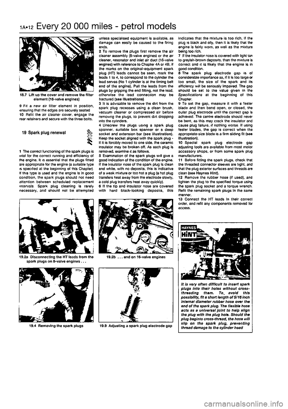
18.7 Lift up the cover and remove the filter element (18-va!ve engines) 9 Fit a new air (liter element In position, ensuring that the edges are securely seated 10 Refit the air cloaner cover, engage the rear retainers and secure with the three bolts.
19 Spark plug renewal
1 The correct functioning of the spark plugs is vital for the correct running and efficiency of the engine. It is essential that the plugs fitted are appropnate for the engine (a suitable type is specified at the beginning of this Chapter. If this type is used and the engine Is In good condition, the spark plugs should not need attention between scheduled replacement intervals Spark plug cleaning Is rarely necessary, and should not be attempted
19.2a Disconnecting tho HT leads from Iho spark plugs on 8-valve engines ...
19.4 Removing the spark plugs
unless specialised equipment Is available, as damage can easily be caused to the firing ends. 2 To remove the plugs first remove the air cleaner assembly (8-vaive engines) or the a»r cleaner, resonator and inlet air duct (16-valve engines) with reference to Chapter 4A or 4B. if the marks on the original-equipment spark plug (HT) leads cannot be seen, mark the leads 1 to 4, to correspond to the cylinder the lead serves (No 1 cylinder is at the timing belt end of the engine). Pull the leads from the plugs by gripping the end fitting, not the lead, otherwise the lead conneciion may be Iractured (see illustrations) 3 It is advisable to remove the dirt from the spark plug recesses using a clean brush, vacuum cleaner or compressed air before removing the plugs, to prevent dirt dropping into the cylinders. 4 Unscrew the plugs using a spark plug spanner, suitable box spanner or a deep socket and extension bar (see illustration). Keep the socket aligned with the spark plug • If it is forcibly moved to one side, the ceramic insulator may be broken off. As each plug is removed examine 4 as fallows. 5 Examination of the spark plugs will give a good Indication of the condition of the engine. If the Insulator nose of the spark plug Is clean and white, with no deposits, this is Indicative of a weak mixture or too hot a plug (a hot plug transfers heal away from the electrode slowly, a cold plug transfers heat away quickly). 6 If the tip and insulator nose are covered with hard black-looking deposits, this
19.2b ... and on 16-valve engines
19.9 Ad|ustlng a spark plug electrode gap
indicates that the mixture Is too rich. If the plug is black and oily, then It is likely that the engine is fairly worn, as well as the mixture being too rich. 7 If the Insulator nose is covered with light tan to greyish-brown deposits, then the mixture Is correct and it is likely that (he engine Is in good condition. 6 The spark plug electrode gap is of considerable importance as, if it Is too large or too small, the size of the spark and its efficiency will be seriously impaired. The gap should be set to the value given in the Specifications at the beginning of this Chapter. 9 To set the gap. measure it with a feeler blade and then bend open, or closed, the outer plug elect/ode until the correct gap l9 achieved. The centre electrode should never be bent, as this may crack the insulator and cause plug I allure, if nothing worse. If using feeler blades, the gap is correct when the appropriate-size blade is a firm sliding fit (see illustration). 10 Special spark plug electrode gap adjusting tools are available from most motor accessory shops, or from some spark plug manufacturers, 11 Before fitting the spark plugs, check that the threaded connector sleeves are tight, and that the plug exterior surfaces and threads are clean (see Haynes Hint). 12 Remove the rubber hose (If used), and tighten the plug to the specified torque using the spark plug socket and a torque wrench, Refit the remaining spark plugs In the same manner. 13 Connect the HT leads In their correct order, and refit any components removed for access.
It is very often difficult to insert spark plugs into their holes without cross-threading them. To, avoid this possibility, fit a short length of Si 16 Inch Internal diameter rubber hose over the end of the spark plug. The flexible hose acts as a universal Joint to help align the plug with the plug hole. Should the plug beginto cross-thread, the hose will slip on the spark plug, preventing thread damage to the cylinder head
Page 47 of 225
Every 20 000 miles - diesel models ib.h
18
Valve clearance check and
adjustment
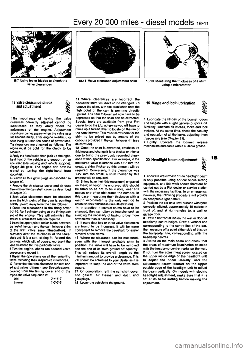
1 The Importance of having the valve clearances correctly adjusted cannot be Distressed, as they vitally affect the performance of the engine. Adjustment should only be necessary when the valve gear nas become noisy, after engine overhaul, or when trying to trace the cause of power loss. The clearances are checked as follows. The engine must be cold for the check to be ttcurate. 2 Apply the handbrake then jack up the right-hand front of the vehicle and support on an axle stand (see Jacking and vehicle support). Engage 4th gear. The engine can now be rotated by turning the right-hand front roadwfteei. 3 Remove ail four glove plugs as described In Chapter 5C. 4 Remove the air cleaner cover and air duct
then
remove the camshaft cover as described
in
Chapter 2C. 6 Each valve clearance must be checked wnen the high point of the cam is pointing directly upward away from the cam follower. 6 Check the clearances in the firing order 1-3-4-2, No 1 cylinder being at the timing belt end of the engine. This will minimise the amount of crankshaft rotation required. 7 Insert the appropriate feeler blade between
the heel
of the cam and the cam follower shim of the First valve (see Illustration). If necessary alter the thickness of the feeler blade until it is a stiff, sliding fit. Record the thickness, which will, of course, represent the
vafve
clearance tor Ihis particular valve. 8 Turn the engine, check the second valve devance and record it. t Repeat the operations on all the remaining valves. recording their respective clearances. 10 Remember that the clearance for inlet and exhaust valves differs - see Specifications. Counting from the timing cover end of the
engine,
the valve sequence is: Wef 2-4-5-7 Etfiat/sf 7-3-6-8
11 Where clearances are incorrect the particular shim will have to be changed. To remove the shim, turn the crankshaft until the high point of the cam is pointing directly upward. The cam follower will now have to bo depressed so that the shim can be extracted. Special tools are available from your Fiat dealer to do the job. otherwise you will have to make up a forked lever to locate on the rim of ihe cam follower. This must allow room for the shim to be prised out by means of the cut-outs provided in the cam follower rim (see illustration). 12 Once Ihe shim is extracted, establish Its thickness and change it for a thicker or thinner one to bring the previously recorded clear-ance within specification, For example, if the measured valve clearance was 1.27 mm too great, a shim thicker by this amount will be required. Conversely, if the clearance was 1.27 mm too small, a shim thinner by this amount will be required. 13 Shims have their thickness (mm) engraved on ihem; although the engraved side should be fitted so as not to be visible, wear still occurs and often obliterates the number. In this case, measuring their thickness with a metric micrometer is the only method to establish their thickness (see illustration). 14 In practice, if several shims have to be changed, they can often be interchanged, so avoiding the necessity of having to buy more new shims than is necessary. 15 If more than two or three valve clearances are found to be incorrect, it will be more convenient to remove the camshaft lor easier removal of the shims. 16 Where no clearance can be measured, even with the Ihinnest available shim in position, the valve will have to be removed and the end of its stem ground off squarely. This will reduce its overall length by the minimum amount to provide a clearance. This job should be entrusted to your dealer as it is important to keep the end of the valve stem square. 17 On completion, refit the camshaft cover and gasket, air cleaner and duct, and glosvplugs. 18 Lower the vehicle to the ground.
19 Hinge and lock lubrication
I
1 Lubricate the hinges of the bonnet, doors and tailgate with a light general-purpose oil. Similarly, lubricate all latches, locks and lock stnkers. At the same time, check the security and operation of all the locks, adjusting them if necessary (see Chapter 11). 2 Lightly lubricate the bonnet release mechanism and cable with a suitable grease.
20 Headlight beam adjustment
I
1 Accurate adjustment of the headlight beam Is only possible using optical beam-setting equipment, and this work should therefore be carried out by a Fiat dealer or service station with the necessary facilities. In an emergency, however, the following procedure will provide an acceptable light pattern. 2 Position the car on a level surface with tyres correctly inflated, approximately 10 metres in front of, and at right-angles to, a wall or garage door. 3 Draw a horizontal tine on the wall or door at headlamp centre height. Draw a vertical line corresponding to the centre line of the car. then measure off a point either side of this, on the horizontal line, corresponding with the headlamp centres. 4 Switch on the main beam and check that the areas of maximum Illumination coincide with the headlamp centre marks on the wall. If not, turn the adjustment screw located on the upper Inside edge of the headlight unit to adjust the beam laterally, and the adjustment screw located on the upper outside edge of the headlight unit to adjust the beam vertically. On models with electric headlight adjustment, make sure that it Is set at its basic setting before making the adjustment,
Page 55 of 225
2A*10 SOHC (8-valve) petrol engine in-car repair procedures
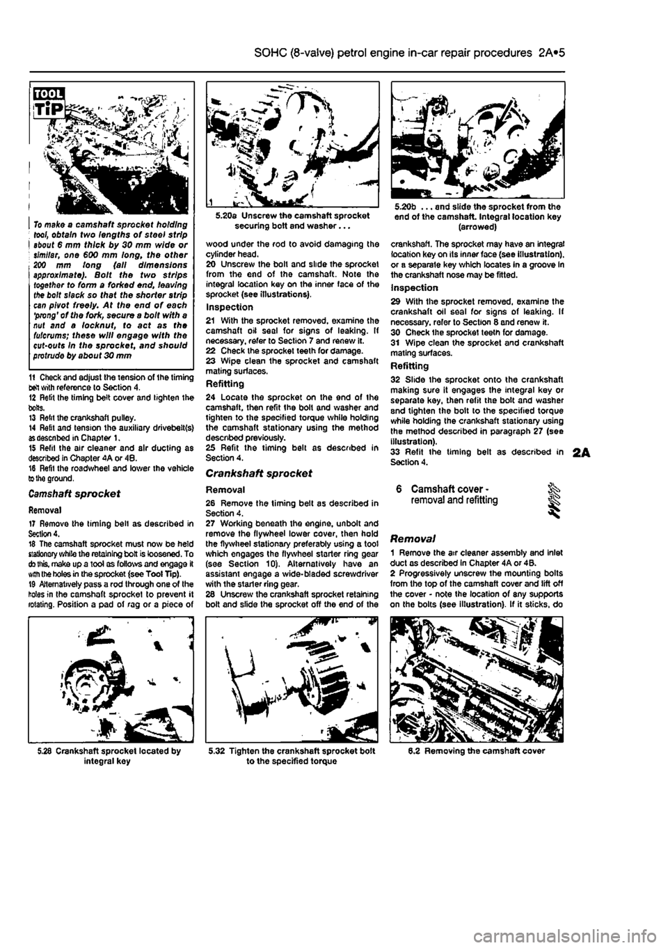
I To make o camshaft sprocket holding ; tool, obtain two lengths of steel strip I about 6 mm thick by 30 mm wide or ; similar, one €00 mm long, the other 200 mm long (all dimensions approximate). Bolt the two strips together to form a forked end, leaving the bolt slack so that the shorter strip can pivot freely. At the end of each 'prong' of the fork, secure a bolt with a nut and a locknut, to act as the fulcrums; these will engage with the cut-outs In the sprocket, and should protrude by about 30 mm
11 Check and adjust the tension of the timing tel with reference to Section 4. 12 Relit Ihe timing belt cover and tighten the bolts. 13 Relit the crankshaft pulley. 14 Refit and tension the auxiliary drivebelt(s)
as
described in Chapter 1. 15 Refil the air cleaner and air ducting as described in Chapter 4A or 48. 16 Refil the roadwheel and lower the vehicle
to the
ground.
Camshaft
sprocket
Removal 17 Remove the timing bell as described in Section 4. 16 The camshaft sprocket must now be held stationary while the retaining bolt is loosened. To
cto this,
make up a tool as follows and engage it
with the
holes
in
the sprocket (see Tool Tip). 19 Alternatively pass a rod through one of the holes in the camshaft sprocket to prevent it rotating. Position a pad of rag or a piece of
integral key
securing bolt and washer...
wood under the rod to avoid damaging the cylinder head. 20 Unscrew the bolt and slide the sprocket from the end of tho camshaft. Note the integral location key on the inner face of the sprocket (see illustrations). Inspection 21 With the sprocket removed, examine the camshaft oil seal for signs of leaking. If necessary, refer to Section 7 and renew it. 22 Check the sprocket teeth for damage. 23 Wipe clean the sprocket and camshaft mating surfaces. Refitting 24 Locate the sprocket on the end of the camshaft, then refit the bolt and washer and tighten to the specified torque while holding the camshaft stationary using the method described previously. 25 Refit the timing belt as described in Section 4.
Crankshaft sprocket
Removal 26 Remove the timing belt as described in Section 4. 27 Working beneath the engine, unbolt and remove the flywheel lower cover, then hold the flywheel stationary preferably using a toot which engages the flywheel starter ring gear (see Section 10). Alternatively have an assistant engage a wide-bladed screwdriver with the stader ring gear. 26 Unscrew the crankshaft sprocket retaining bolt and slide the sprocket off the end of the
^P
5.32 Tighten the crankshaft sprocket bolt to the specified torque
end of the camshaft Integral location key (arrowed)
crankshaft. The sprocket may have an integral location key on its inner face (see illustration), or a separate key which locates in a groove in the crankshaft nose may be fitted. Inspection 29 With the sprocket removed, examine the crankshaft oil seal for signs of leaking. If necessary, refer to Section 8 and renew it. 30 Check the sprocket teeth for damage. 31 Wipe clean the sprocket and crankshaft mating surfaces. Refitting 32 Slide the sprocket onto the crankshaft making sure it engages the integral key or separate key, then refit the bolt and washer and tighten the bolt to the specified torque while holding the crankshaft stationary using the method described in paragraph 27 (see illustration). 33 Refit the timing belt as described in Section 4.
6 Camshaft cover -removal and refitting
Removal 1 Remove the air cleaner assembly and inlet duct as described in Chapter 4A or 4B. 2 Progressively unscrew the mounting bolts from the top of the camshaft cover and lift off the cover • note the location of any supports on the bolts (see illustration). If it sticks, do
6.2 Removing the camshaft cover
Page 59 of 225
2A*10 SOHC (8-valve) petrol engine in-car repair procedures
require cutting with a sharp Knife to release
the sump.
Clean away all old gasket material. Refitting
5
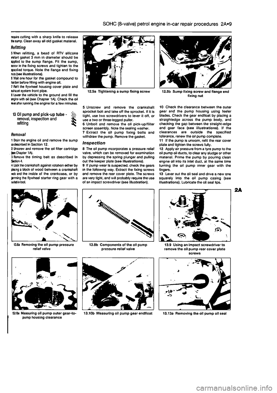
Wwn refitting, a bead of RTV silicone nsiant gasket 3 mm in diameter should be applied lo the sump flange. Fit the sump, screw in tha fixing screws and tighten to the spscabed torque. Note the flange end fixing
nuts
(see illustrations).
6
'//ait one hour for the gasket compound to henjai before filling with engine oil. 7 Refit the flywheel housing cover plate and tohaust system front pipe.
8
lower the vehicle to the ground and fill the eng'rewith oil (see Chapter 1A). Check the oil
fevai
alter running the engine for a few minutes.
13 Oil
pump and pick-up tube - >>>
removal,
inspection and ^ refitting ^
Removal 1 Drain tho engine oil and remove the sump adsswibed in Section 12.
%
Unscrew and remove the oil filter cartridge .
(see
Chapter 1A|. 3 Remove the timing belt as described In
Section A.
4
Lock
the crankshaft against rotat>on either by tfacng a block of wood between a crankshaft wb and the inside of the crankcase, or by jjmning the flywheel starter ring gear with a
lutabfe
tool.
I3v8a Removing the oil pump pressure relief valve
12.5a Tightening a sump fixing screw
5 Unscrew and remove the crankshaft sprocket boll and take off the sprocket. If it is tight, use two screwdrivers to lever it off, or use a two or three-legged puller. 6 Unbolt and remove the oil pick-up/filter screen assembly. Note the sealing washer. 7 Extract the oil pump fixing bolts and withdraw the pump. Remove the gasket.
Inspection 8 The oil pump incorporates a pressure relief valve, which can be removed for examination by depressing the spring plunger and pulling out the keeper plate (see illustrations). 9 If pump wear Is suspected, check the gears in the following way. Extract the fixing screws and remove the rear cover plate. The screws are very tight, and will probably require the use of an impact screwdriver (see illustration).
pressure relief valve
12.5b Sump fixing screw and flange end fixing nut
10 Check the clearance between the outer gear and the pump housing using feeler blades. Check the gear endtloat by placing a straightedge across the pump body, and checking the gap between the straight-edge and gear face (see illustrations). If the clearances are outside the specified tolerance, renew the oil pump complete. 11 If the pump is unworn, refit the rear cover plate and tighten the screws fully. 12 Apply air pressure from a tyre pump to the oil pump oil ducts, to clear any sludge or other material. Prime the pump by pouhng clean engine oil into its inlet duct, at the same time turning the oil pump inner gear with the fingers. 13 Lever out the oil seal and drive a new one squarely into the oil pump casing (see illustrations). Lubricate the oil seal lips.
13.9 Using an impact screwdriver to remove the oil pump rear cover pfate screws
13,19s Measuring oil pump outer gear-to- 13.10b Measuring oil pump gear endtloat pump housing clearance
Page 67 of 225
2B*7 DOHC (16-valve) petrol engine in-car repair procedures
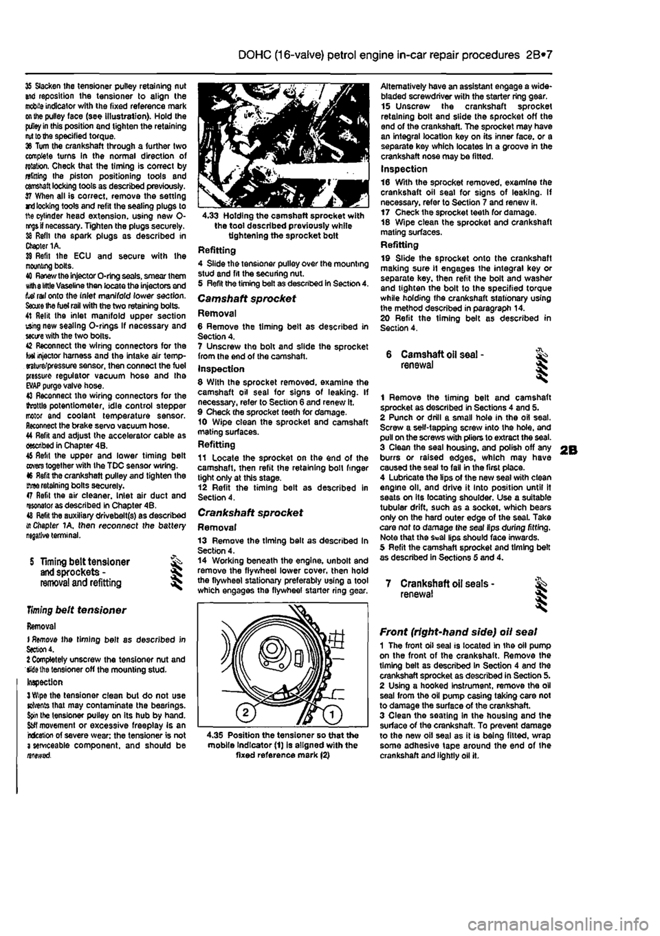
35 Slacken the tensioner pulley retaining nut and reposition the tensioner to align the
mobile
indicator with the fixed reference mark
on the
pulley face (see illustration). Hold the
pdley in
this position and tighten the retaining
nut to the
specified torque. 36 Turn the crankshaft through a further two complete turns In the normal direction of rotation. Check that the timing is correct by alining Ihe piston positioning tools and
camshaft
locking tools as described previously. 37 When all is correct, remove the setting rri
locking
tools and refit the sealing plugs to 1ft© cylinder head extension, using new 0-
nr^s if
necessary. Tighten the plugs securely. 38 Refit the spark plugs as described in Chapter 1A. 39 Refit Ihe ECU and secure with Ihe mooning bolts. 40
Renew the
injector O-ring seals, smear them Kith
8 little
Vaseline then locate the injectors and tef rail onto the inlet manifold lower section.
Saute Ihe fuel rail
with the two retaining bolts. 41 Relit the inlet manifold upper section using new sealing O-rlngs If necessary and
sectre
with the two bolts. 42 Reconnect the wiring connectors for the tot injector harness and the intake air temp-erature/pressure sensor, then connect the fuel pressure regulator vacuum hose and tha
EVAP
purge valve hose. 43 Reconnect the wiring connectors for the ihrottls potentiometer, idle control stepper motor and coolant temperature sensor. Reconnect the brake servo vacuum hose. 44 Refit and adjust the accelerator cable as described in Chapter 4B. 46 Refit the upper and lower timing belt
covers
together with the TDC sensor wiring. 46 Refit the crankshaft pulley and tighten the
three
retaining bolts securely. 47 Refit the air cleaner. Inlet air duct and resonator as described in Chapter 4B. 48
Refit
tha auxiliary drivebelt(s) as described i/t Chapter 1A, then reconnect the battery
S Timing belt tensioner
and
sprockets -
removal
and refitting
Timing
belt tensioner
Removal I
Remove
the timing belt as described in
Section
4. 1 Completely unscrew the tensioner nut and Wiethe tensioner off the mounting stud-Inspection
3 Wipe
the tensioner clean but do not use Kfrents that may contaminate the bearings.
Spin
the tensioner pulley on its hub by hand.
Sfcfl
movement or excessive freeplay is an rcfceticn of severe wear: the tensioner is not 3 serviceable component, and should be nnewsd.
4.33 Holding the camshaft sprocket with the tool described previously while tightening the sprocket bolt Refitting 4 Slide the tensioner pulley over the mounting stud and fit the securing nut. 5 Refit the timing belt as described in Section 4. Camshaft sprocket Removal 6 Remove the timing belt as described in Section 4. 7 Unscrew the bolt and slide the sprocket from the end of the camshaft. Inspection 8 With the sprocket removed, examine the camshaft oil seal for signs of leaking. If necessary, refer to Section 6 and renew it. 9 Check the sprocket teeth for damage. 10 Wipe clean the sprocket and camshaft mating surfaces. Refitting 11 Locate the sprocket on the end of the camshaft, then refit the retaining boll finger tight only at this stage. 12 Refit the timing belt as described in Section 4.
Crankshaft sprocket Removal 13 Remove the timing bell as described In Section 4. 14 Working beneath the engine, unbolt and remove the flywheel lower cover, then hold the flywheel stationary preferably using a tool which engages the flywheel starter ring
<
Alternatively have an assistant engage a wide-bladed screwdriver with the starter ring gear. 15 Unscrew the crankshaft sprocket retaining bolt and slide the sprocket off the end of the crankshaft. The sprocket may have an integral location key on its inner face, or a separate key which locates In a groove in the crankshaft nose may be fitted. Inspection 16 With the sprocket removed, examine the crankshaft oil seal for signs of leaking. If necessary, refer to Section 7 and renew it. 17 Check the sprocket teeth for damage. 18 Wipe clean the sprocket and crankshaft mating surfaces. Refitting 19 Slide the sprocket onto the crankshaft making sure
11
engages the integral key or separate key, then refit the bolt and washer and tighten the bolt to the specified torque while holding the crankshaft stationary using the method described in paragraph 14. 20 Refit the timing belt as described in Section 4.
6 Camshaft
oil
seal -renewal
1 Remove the timing belt and camshaft sprocket as described in Sections 4 and 5. 2 Punch or drill a small hole in the oil seal. Screw a self-tapping screw into the hole, and pull on the screws with pliers to extract the seal. 3 Clean the seal housing, and polish off any burrs or raised edges, which may have caused the seal to fall in the first place. 4 Lubricate the lips of the new seal with clean engine oil, and drive it into position until It seats on its locating shoulder. Use a suitable tubular drift, such as a socket, which bears only on the hard outer edge of the seal. Take care nof to damage the seal lips during fitting. Note that the Seal lips should face inwards. 5 Refit the camshaft sprocket and timing belt as described in Sections 5 and 4.
7 Crankshaft oil seats -renewal I
4.35 Position the tensioner so that the mobile Indicator (1) is aligned with the fixed reference mark (2)
Front (right-hand side) oil seal 1 The front oil seal is located in the oil pump on the front of the crankshaft. Remove the timing belt as described in Section 4 and the crankshaft sprocket as described in Section 5. 2 Using a hooked Instrument, remove the oil seal from the oil pump casing taking care not to damage the surface of the crankshaft. 3 Clean the seating in the housing and the surface of the crankshaft. To prevent damage to the new oil seal as it is being fitted, wrap some adhesive tape around the end of the crankshaft and lightly oil it.
Page 78 of 225
2C*2 Diesel engine in-car repair procedures
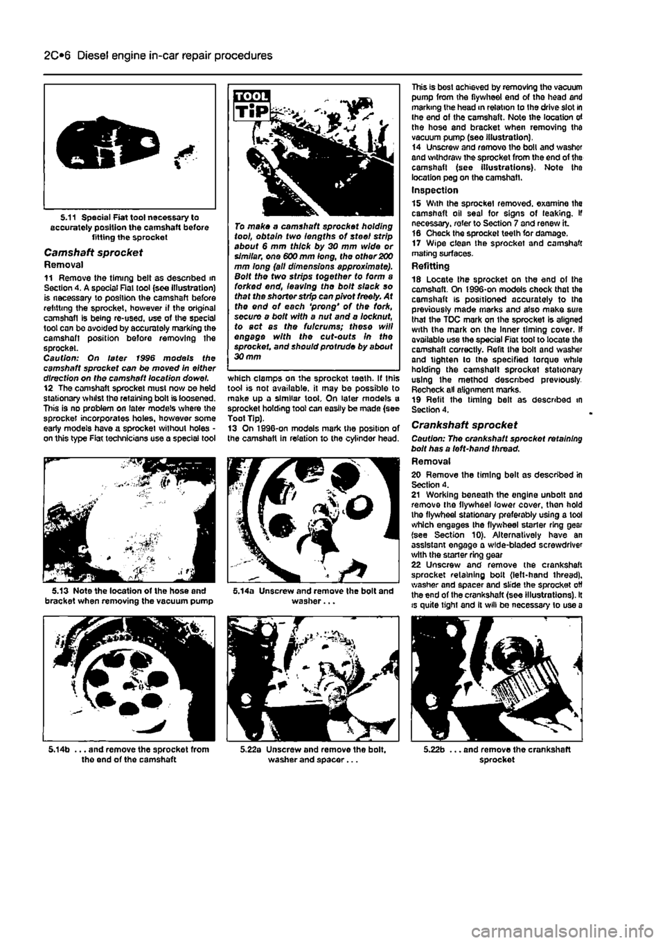
5.11 Special Fiat tool necessary to accurately position the camshaft before fitting the sprocket
Camshaft sprocket Removal 11 Remove the timing belt as descnbed in Section 4. A special Rat tool (see illustration) is necessary to position the camshaft before refitting the sprocket, however il the original camshafl Is being re-used, use of the special tool can be ovoided by accurately marking the camshaft position before removing the sprocket. Caution: On later 1996 models the camshaft sprocket can be moved In either direction on tho camshaft location dowel. 12 The camshaft sprocket must now oe held stationary whilst the retaining bolt is loosened. This is no problem on later models where the sprocket incorporates holes, however some early models have a sprocket without holes • on this type Fiat technicians use a special tool
V*— r^r
To make a camshaft sprocket holding tool, obtain two lengths of steel strip about 6 mm thick by 30 mm wide or simllar, one 600 mm long, the other 200 mm long (all dimensions approximate). Bolt the two strips together to form a forked end, leaving tho bolt slack so that the shorter strip can pivot freely. At the end of each 'prong' of the fork, secure a bolt with a nut and a locknut, to act as the futcrums; theso will engage with the cut'Outs In the sprocket, and should protrude by about 30 mm
which clamps on the sprockot teeth. If this tool is not available, it may be possible to make up a similar tool. On later models a sprocket holding tool can easily be made (see Toot Tip). 13 On 1996-on models mark the position of the camshaft in relation to the cylinder head.
5.14a Unscrew and remove the bolt and washer...
This is best achieved by removing tho vacuum pump from the flywheel end of the head and marking the head in relation to Ihe drive slot in ihe end of the camshaft. Note the location of the hose and bracket when removing tha vacuum pump (seo illustration). 14 Unscrew and remove tho boll and v/ashof and withdraw the sprocket from the end of tha camshaft (see Illustrations). Note tha location peg on the camshafl. Inspection 15 With the sprocket removed, examine the camshaft oil seal for signs of leaking. If necessary, rater to Section 7 and renew it 16 Check the sprocket teeth for damage. 17 Wipe clean the sprocket and camshaft mating surfaces-Refitting 18 Locate the sprocket on the end of the camshaft. On J996-on models chock that the camshaft is positioned accurately to tho previously made marks and also make sura thai the TOC mark on Ihe sprocket Is aligned with the mark on the Inner timing cover. If avoiiablo use the special Fiat toot to locate the camshaft correctly. Rofil the bolt and washer and tighten lo the specified torque while holding the camshalt sprocket stationary using the method descnbed previously. Recheck all alignment marks. 19 Refit the timing belt as described in Section 4.
Crankshaft sprocket Caution: The crankshaft sprockot retaining bolt has a left-hand thread. Removal 20 Remove the timing belt as described in Section 4. 21 Working beneath the engine unbolt and remove the flywheel lower cover, than hold the flywheel stationary preferably using a tool which engages the flywheel starter ring gear (see Section 10). Alternatively have an assistant engage a wide-bladed screwdriver with the starter ring gear 22 Unscrew and remove (he crankshaft sprocket retaining bolt (left-hand thread), washer and spacer and slide the sprocket off the end of the crankshaft (see illustrations). It is quite tight and il will be necessary to use a
5.14b ... and remove the sprocket from tho end of the camshaft 5.22a Unscrew and remove the bolt, washer and spacer... 5.22b ... and remove the crankshaft sprocket
Page 83 of 225
Diesel engine in-car repair procedures 2C*11
r
<3^
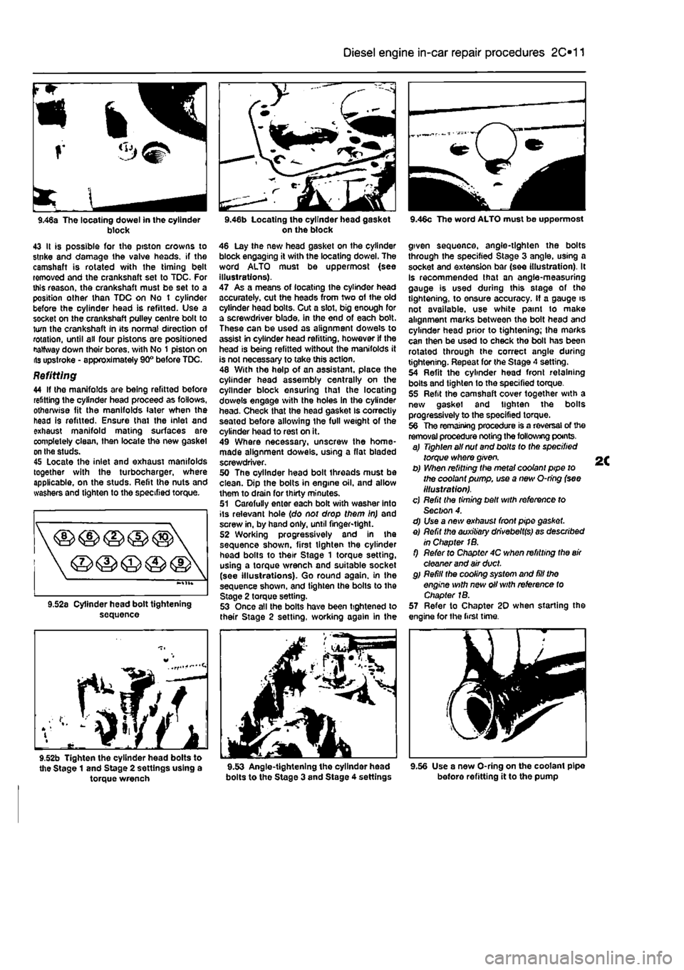
9.46a The locating dowel in the cylinder block 43 It is possible for the ptston crowns to stnke and damage the valve heads, if the camshaft is rotated v/ith the timing belt removed and the crankshaft set to TDC. For this reason, the crankshaft must be set to a position other than TDC on No t cylinder before the cylinder head is refitted. Use a socket on the crankshaft pulley centre bolt to turn the crankshaft in its normal direction of rotation, until all four pistons are positioned Halfway down their bores, v/ith No 1 piston on lis upstroke - approximately 90° before TDC.
Refitting 44 If the manifolds are being refitted before refitting the cylinder head proceed as follows, otherwise fit the manifolds later when the head is refitted. Ensure thai the inlet and exhaust manifold mating surfaces are completely clean, then locale the new gasket on the studs. 45 Locate the inlet and exhaust manifolds together with the turbocharger, where applicable, on the studs. Refit the nuts and washers and tighten to the specified torque.
sequence
f^/f
9.52b Tighten the cylinder head bolts to the Stage 1 and Stage 2 settings using a torque wrench
on the block 46 Lay the new head gasket on the cylinder block engaging it with the locating dowel. The word ALTO must be uppermost (see illustrations). 47 As a means of locating Ihe cylinder head accurately, cut the heads from two of the old cylinder head bolts. Cut a slot, big enough for a screwdriver blade, in the end of each bolt. These can be used as alignment dowels to assist in cylinder head refitting, however If the head is being refitted without the manifolds it is not necessary to take this action. 48 With the help of an assistant, place the cylinder head assembly centrally on the cylinder block ensuring thai the locating dowels engage with Ihe holes in the cylinder head. Check that the head gasket Is correctly seatod before allowing the full weight of the cylinder head to rest on it. 49 Where necessary, unscrew the home-made alignment dowels, using a flat bladed screwdriver. 50 The oyllnder head bolt threads must be clean. Dip the bolts in engine oil. and allow them to drain for thirty minutes. 51 Carefully enter each bolt with washer into its relevant hole (do not drop them in) and screw in, by hand only, until finger-tight. 52 Working progressively and In the sequence shown, first tighten the cylinder head bolts to their Stage 1 torque setting, using a torque wrench and suitable socket (see illustrations). Go round again, in the sequence shown, and tighten the bolls to the Stage 2 torque setting. 53 Once all the bolts have been tightened to their Stage 2 setting, working again in the
bolts to the Stage 3 and Stage 4 settings
9.46c The word ALTO must be uppermost
given sequence, angle-tighten the bolts through the specified Stage 3 angle, using a socket and extension bar (see illustration). It Is recommended that an angle-measuring gauge is used during this stage of the tightening, to ensure accuracy. If a gauge is not available, use white paint to make alignment marks between the bolt head and cylinder head prior to tightening; the marks can then be used to check tho bolt has been rotated through the correct angle during tightening. Repeat for the Stage 4 setting. 54 Refit the cylinder head front retaining bolts and tighten lo the specified torque. 55 Refit the camshaft cover together with a new gasket and tighten the bolts progressively to the specified torque. 56 The remaining procedure is a reversal of the removal procedure noting the following points. a) Tighten all nut and bolts to the specified torque where given. b) When refitting the metal coolant pipe to the coolant pump, use a new O-ring (see illustration). cj Refit the timing belt with reference to Section 4. d) Use a new exhaust front pipe gasket. e) Refit the auxiliary dhvebeltfs) as described in Chapter 1B. f) Refer to Chapter 4C when refitting the
air
cleaner and air duct. g) Refill the cooling system and fill the engine with new oil with reference to Chapter 1B. 57 Refer to Chapter 20 when starting the engine for the first time.
9.56 Use a new O-ring on the coolant pipe before refitting it to the pump