gearbox FIAT PUNTO 1998 176 / 1.G Workshop Manual
[x] Cancel search | Manufacturer: FIAT, Model Year: 1998, Model line: PUNTO, Model: FIAT PUNTO 1998 176 / 1.GPages: 225, PDF Size: 18.54 MB
Page 10 of 225
Roadside repairs 0.9
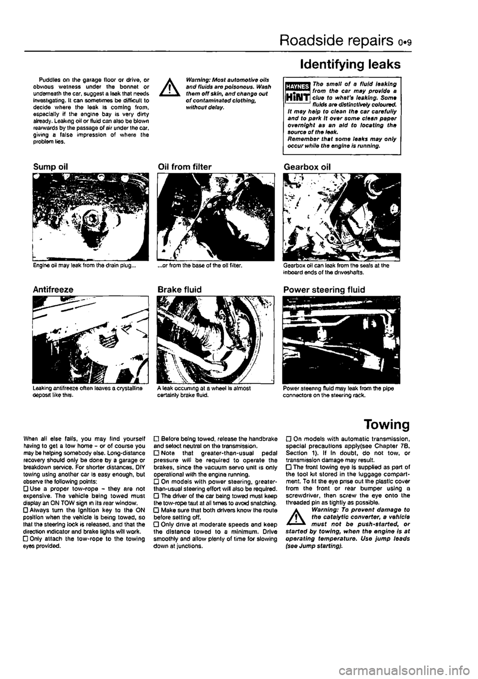
Puddles on the garage floor or drive, or obvious wetness under the bonnet or underneath the car, suggest a leak that needs Investigating. It can sometimes be difficult to decide where the leak is coming from, especially if the engine bay is very dirty already. Leaking oil or fluid can also be blown rearwards by the passage of air under the car, giving a false impression of where the problem lies.
A
Warning: Most automotive oils and fluids aro poisonous. Wash them off skin, and change out of contaminated clothing, without delay.
Identifying leaks
The smell of 0 fluid leaking from the car may provide a clue to what's leaking. Some fluids are distinctively coloured. It may help to clean the car carefully and to park It over some clean paper overnight as an aid to locating the source of the leak. Remember that some leaks may only occur while the engine is running.
Sump oil
Engine oil may leak from the drain plug...
Antifreeze
Leaking antifreeze often leaves a crystalline oeposit like this.
Oil from filter
A leak occurring at a wheel Is almost certainly brake fluid.
Gearbox oil
Gearbox oil can leak from the seals at the inboard ends of the drivoshafts.
Power steering fluid
Power steering fluid may leak from the pipe connectors on the steering rack.
When ail else falls, you may llnd yourself having to get a tow home - or of course you may be helping somebody else. Long-distance recovery should only be done by a garage or breakdown service. For shorter distances. OIY towing using another car is easy enough, but observe the following points: • Use a proper tow-rope - they are not expensive. The vehicle being towed must display an ON TOW sign in its rear window. • Always turn the Ignition key to the ON position when the vehicle is being towed, so that the steering lock is released, and that the direction indicator and brake lights will work. • Only attach the tow-rope to the towing eyes provided.
• Before being towed, release the handbrake and select neutral on the transmission. • Note that greater-then-usual pedal pressure will be required to operate the brakes, since the vacuum servo unit is only operational with the engine running. • On models with power steering, greater-than-usual steering effort will also be required. • The driver of the car being towed must keep the tow-rope taut at all times to avoid snatching. • Make sure that both drivers know the route before setting off. • Only dnve at moderate speeds and keep the distance towed to a minimum. Drive smoothly and allow plenty of time for slowing down at junctions.
Towing
• On models with automatic transmission, special precautions apply(see Chapter 7B. Section 1). If In doubt, do not tow, or transmission damage may result. • The front towing eye is supplied as part of the tool kit stored in the luggage compart-ment. To fit the eye pnse out the plastic cover from the front or rear bumper using a screwdriver, then screw the eye onto the threaded pin as tightly as possible.
A
Warning: To prevent damage to the catalytic converter, e vehicle must not be push'started, or started by towing, when the engine is at operating temperature. Use jump leads (see Jump starting).
Page 18 of 225
Lubricants and fluids 0.17
Lubricants and fluids
Engine Petrol Multigrade engine oil, viscosity SAE15W/40, to API SG/CD or better (Duckhams QXR Premium Petrol Engine Oil, or Duckhams Hypergrade Petrol Engine Oil) Diesel Multigrade engine oil, viscosity SAE15W/40, to API SG/CD or better Duckhams QXR Premium Diesel Engine Oil, or Duckhams Hypergrade Diesel Engine Oil) Cooling system Ethylene glycol-based antifreeze and soft water (Duckhams Antifreeze & Summer Coolant) Manual gearbox Hypoid gear oil, viscosity SAE80W to API GL4 (Duckhams Hypoid Gear Oil SOW GL-4) Automatic transmission Dexron type II automatic transmission fluid (ATF) (Duckhams ATF Autotrans III) Braking system Hydraulic fluid to SAE J1703F or DOT 4 (Duckhams Universal Brake & Clutch Fluid) Power steering Dexron type II automatic transmission fluid (ATF) (Duckhams ATF Autotrans Hi)
Choosing your engine oil
Engines need oil. not only to lubricate moving parts and minimise wear, but also to maximise power output and to Improve fuel economy. By introducing a simplified and improved range of engine oils. Duckhams has taken away the confusion and made it easier for you lo choose the right oil for your engine.
HOW ENGINE OIL WORKS
• Beating friction Without oil. the moving surfaces inside your engine will rub together, heat up and melt, quickly causing the engine to seize. Engine oil creates a film which separates these moving parts, preventing wear and heat build-up.
• Cooling hot-spots Temperatures Inside the engine can exceed 1000°
C.
The engine oil circulates and acts as a coolant, transferring heat from the hot-spots to the sump.
• Cleaning the engine internally Good quality engine oils clean the Inside of your engine, collecting and dispersing combustion deposits and controlling them until they are trapped by the oil niter or flushed out at oil change.
OIL CARE - FOLLOW THE CODE To handle and dispose of used engine oil safety, always: • Avoid skin contact with used engine oil. Repeated or prolonged contact can be harmful. • Dispose of used oil and empty packs In a responsible manner In an authorised disposal site. tti Call 0800 663366 to find qIqq f £ the one nearest to you. Never tip oil down drains or onto the ground.
DUCKHAMS ENGINE OILS For the driver who demands a premium quality oil for complete reassurance, we recommend synthetic formula Duckhama QXR Premium Engine Oils. For the driver who requires a straight-forward quality engine oil, we recommend Duckhams Hypergrade Engine Ote.
For further information and advice, call the Duckhams UK Helpline on 0800 212988.
^SGCKHAMS
Page 32 of 225
Every 20 000 miles - petrol models 1A.13
20 Ignition system check
81
21 Engine management system check
A
Warning: Voltages produced by an electronic ignition system are considerably higher than those produced by conventional ignition systems. Extreme care must be taken when working on the system with the Ignition switched on. Persons with surgically-Implanted cardiac pacemaker devices should keep well clear of the ignition circuits, components and test oquipment. 1 The ignition system components should be checked for damage or deterioration as follows.
General component check 2 The spark plug (HT) leads should be checked whenever new spark plugs are fitted. 3 Pull the leads from the plugs by gripping
the end
fitting, not the lead, otherwise the lead connection may be fractured.
Ensure that the leads are i numbered before removing i them, to avoid confusion when refitting
4 Check Inside the end fitting for signs of corrosion, which will look like a white crusty powder. Push the end fitting back onto the spark plug, ensuring that it is a tight fit on the plug. if not, remove the lead again and use pliers to carefully crimp the metal connector inside the end fitting until it fits securely on the
end
of the spark plug. 5 Using a clean rag, wipe Ihe emlre length of the lead to remove any built-up dirt and grease. Once the lead is clean, check for bums, cracks and other damage. Do not bend the lead excessively, nor pull the lead lengthways - the conductor inside might break. 6 Disconnect the other end of the lead from the ignition coll. Again, pull only on the end fitting. Check for corrosion and a tight fit in the
same
manner as the spark plug end. Refit the bad securely on completion. 7 Check the remaining leads one at a time, in
ihe same
way. 8 if new spark plug (HT) leads are required, purchase a set for your specific car and engine. 9 Even with the ignition system In first-class condition, some engines may still occasionally experience poor starting attributable to damp ignition components. To disperse moisture, a water-dispersant aerosol should be liberally
Ignition timing -
check
and adjustment 10 Check the ignition timing as described In Chapter 58.
1 This check is part of the manufacturer's maintenance schedule, and Involves testing Ihe engine management system using special dedicated test equipment. Such testing will allow the test equipment to read any fault codes stored in the electronic control unit memory. 2 Unless a fault is suspected, this test te not essential, although it should be noted that it is recommended by the manufacturers. 3 If access to suitable test equipment is not possible, make a thorough check of all ignition, fuel and emission control system components, hoses, and wiring, for security and obvious signs of damage. Further details of the fuet system, emission control system and ignition system can be .found In the relevant parts of Chapters 4 and 5.
22 Hinge and lock lubrication %
1
1 Lubricate the hinges of the bonnet, doors and tailgate with a light general-purpose oil. Similarly, lubricate ail latches, locks and lock strikers. At the same time, check the security and operation of all the locks, adjusting them If necessary (see Chapter 11). 2 Lightly lubricate the bonnet release mechanism and cable with a suitable grease.
23 Headlight beam adjustment % & ^
1 Accurate adjustment of the headlight beam is only possible using optical beem-setting equipment, and this work should therefore be carried out by a Fiat dealer or service station with the necessary facilities. In an emergency, however, the following procedure will provide an acceptable light pattern. 2 Position the car on a level surface with tyres correctly inflated, approximately 10 metres in front of. and at right-angles to, a wall or garage door, 3 Draw a horizontal line on the wall or door at headlamp centre height. Draw a vertical line corresponding to the centre line of the car, then measure off a point either side of this, on the horizontal line, corresponding with the headlamp centres. 4 Switch on the main beam and check that the areas of maximum illumination coincide with the headlamp centre marfcs on Ihe wall, if not. turn the adjustment screw located on the upper inside edge of the headlight unit to adjust the beam laterally, and the adjustment screw located on the upper outside edge of the headlight unit to adjust the beam
vertically. On models with electric headlight adjustment, make sure that it is set at its basic setting before making the adjustment.
24 Road test
Instruments and electrical equipment 1 Check the operation of all Instruments and electrical equipment. 2 Make sure that all instruments read correctly, and switch on all electrical equipment in turn, to check that it functions properly.
Steering and suspension 3 Check for any abnormalities in the steering, suspension, handling or road feel. 4 Drive the vehicle, and check that there are no unusual vibrations or noises. 5 Check that the steering feels positive, with no excessive sloppiness, or roughness, and check for any suspension noises when cornering and driving over bumps.
Drivetrain 6 Check the performance of the engine, clutch (where applicable), transmission and driveshafts. 7 Listen for any unusual noises from the engine, clutch and gearbox/transmission. 8 Make sure that the engine runs smoothly when Idling, and that there Is no hesitation when accelerating. 9 Check that, where applicable, the clutch action Is smooth and progressive, that the drive is taken up smoothly, and that the pedal travel is not excessive. Also listen for any noises when the clutch pedal is depressed. 10 On manual gearbox models, check that all gears can be engaged smoothly without noise, and that the gear lever action is not abnormally vsgue or notchy. 11 On automatic transmission models, check that all Ihe gear positions can be selected with the vehicle at rest, if any problems are found, they should be referred to a Flat dealer. 12 Listen for a metallic clicking sound from the front of the vehicle, as the vehicle is driven slowly in a circle with the steering on full-lock. Carry out this check in both directions. If a clicking noise is heard, this Indicates wear in a drtveshaft joint, In which case renew the joint if necessary.
Check the braking system 13 Make sure that the vehicle does not pull to one side when braking, and that the wheels do not lock prematurely when braking hard. 14 Check that there is no vibration through the steering when braking. 15 Check that the handbrake operates correctly without excessive movement of the lever, and that It holds the vehicle stationary on a slope.
Page 162 of 225
7A»1
Chapter 7 Part A:
Manual transmission
Contents
Gearchange lever and linkage - removal and refitting 2 General information 1 Manual transmission oil level check See Chapter 1A or 18 Manual transmission oil renewal See Chapter 1A or 1B
Manual transmission overhaul • general information 4 Manual transmission • removal and refitting 3 Reversing light switch • testing, removal and refitting 5
Degrees of difficulty
Easy, suitable
for Faiity
easy,
suitable FaMycffficult, ^ Difficult,
sutable fa-
Verycfifficutt, ^
novice with
little
1
for beginner with suitable
for
competent experienced DIY * * < siitable
for
expert
DIY
jR or professional ^ experience 1
some
experience DIYmechanic ^ mechanic * * < siitable
for
expert
DIY
jR or professional ^
Specifications
General Type
Designation: 1108 cc petrol engine 1242 cc petrol engine Non-turbo diesel engine Turbo diesel engine
Torque wrench settings Gear lever support nut Gear lever to mounting Reverse gear inhibitor cable to transmission Reversing light switch Selector rod-to-gear lever nut Speedometer drive Transmission-to-engine bolt/nut
Transverse mounted, front wheel drive layout with integral transaxle differential/final drive. 5 or 6 forward speeds, 1 reverse speed
C.S14.5.10 (5-speed) or C.514.6.10 (6-speed) C.514.5.1Q/13 (5-speed) C.514.5.13 (5-speed) C.510.5.17 (5-speed)
Nm Ibftl 6 4 49 36 30 22 40 30 17 13 12 9 es 63
1 Genera) Information
The transmission is contained In a cast-aluminium alloy casing bolted to the engine's left-hand end, and consists of the gearbox end final drive differential, Drive Is transmitted from the crankshaft via the clutch to the Input shaft, which has a spiined extension to accept the clutch friction
plate, and rotates in roller bearings at its right-hand end and ball bearings at its left-hand end (on 6-speed versions the left-hand extension rotates In a roller bearing). From the input shaft, drive is transmitted to tho output shaft, which rotates In roller bearings at Its right-hand end. and ball bearings at its left* hand end (on 6-speed versions the left-hand extension rotates in ball bearings). From the output shaft, the drive is transmitted to the differential crownwheel, which rotates with the differential case and gears in taper roller bearings, thus driving the sun gears and
driveshafts. The rotation of the differential gears on their shaft allows the inner roadwheel to rotate at a slower speed than the outer roadwheel when the car is cornering. The Input and output shaftB are arranged side by side, parallel to the crankshaft and driveshafts, so that their gear pinion teeth are In constant mesh. In the neutral position, the relevant input shaft and output shaft gear pinions rotate freely, so that drive cannot be transmitted to the output shaft and crownwheel.
Page 172 of 225
6*172
Chapter 8
Driveshafts
Contents
Oriveshaft gaiter check See Chapter 1A or 1B General information 1 Oriveshaft overhaul and rubber gaiter renewal 3 intermediate driveshaft - removal and refitting 4 Driveshafts - removal and refitting 2
Degrees of difficulty
Easy,
suitable for ^ novtoewithittle experience ^
Fatly
easy,
suitable for beginner with
some experience
^
Fairty
difficult, suitable
tor
competent OtYmechanlc
Difficult,
suitable for experienced DIY mechanic ^
Veiydfficult, ^
suitable
for
expert DIY
or professional ^
Specifications
General Type
Lubrication lubricant type
Torque wrench settings Driveshaft nut* All models except turbo diesel (M22 plain) Turbo diesel (M24 with staking and captive washer) Roadwheel bolts Suspension strut-to-hub carrier bolts Track-rod balljolnt-to-hub carrier 'Use a new nut.
Unequal-length, solid steel shafts, splined to Inner and outer constant velocity joints. Intermediate shaft with support bearing on turbo diesel models with equal length driveshafts.
Fiat specification grease, supplied with gaiter repair kit
Nm Ibfft
240 177 280 207 85 63 70 52 40 30
1 General information
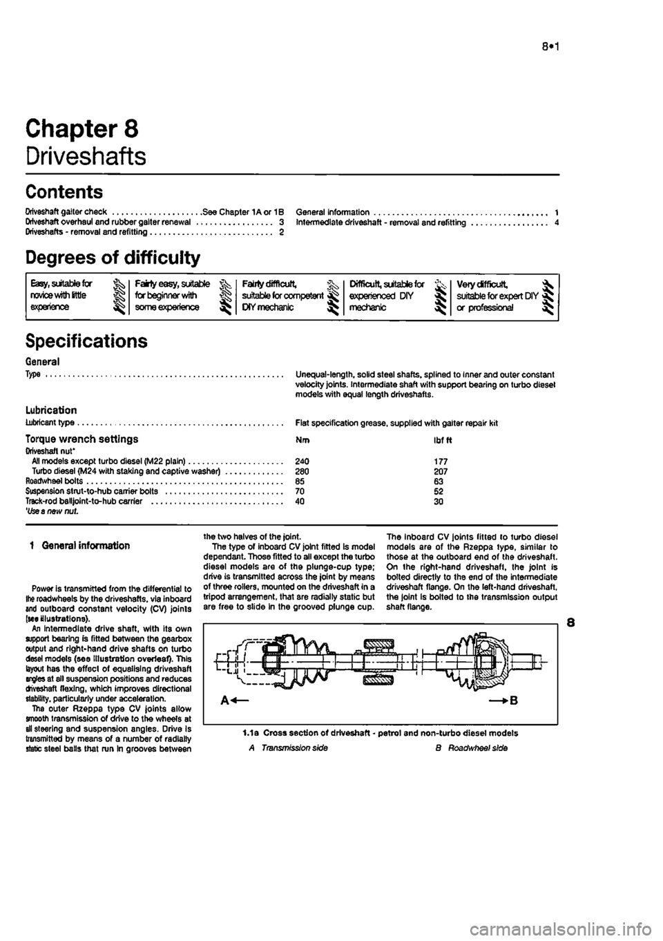
Power is transmitted from the differential to
Ihe
roadwheels by the driveshafts. via inboard and outboard constant velocity (CV) joints (we illustrations). An intermediate drive shaft, with its own support bearing is fitted between the gearbox output and right-hand drive shafts on turbo desei models (see Illustration overleaf). This layout has the effect of equalising driveshaft angles at sll suspension positions and reduces tfveshaft flexing, which improves directional stability, particularly under acceleration. The outer Rzeppa type CV joints allow smooth transmission of drive to the wheels at all steering and suspension angles. Drive Is transmitted by means of a number of radially static steel balls that run In grooves between
the two halves of the joint. The type of inboard CV joint fitted is model dependant. Those fitted to all except the turbo diesel models are of the plunge-cup type; drive is transmitted across the joint by means of three rollers, mounted on the driveshaft in a tripod arrangement, that are radially static but are free to slide in the grooved plunge cup.
The inboard CV joints fitted to turbo diesel models are of the Rzeppa type, similar to those at the outboard end of the driveshaft. On the right-hand driveshafl, the joint is bolted directly to the end of the intermediate driveshaft flange. On the left-hand driveshaft, the joint is bolted to the transmission output shaft flange.
1.1a Cross section of driveshaft - petrol and non-turbo diesel models A Transmission side B Roadwheef side
Page 174 of 225
Driveshafts 8*3
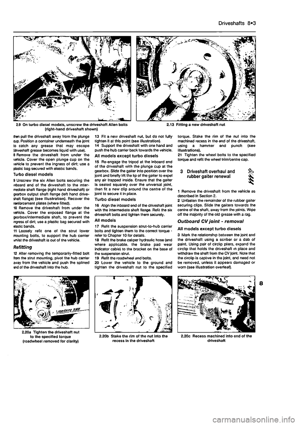
2.9 On turbo diesel models, unscrew the driveshaft Allen bolts (right-hand driveshaft shown) 2.13 Fitting a new driveshaft nut
then pull the driveshaft away from the plunge cup. Position a container underneath the joint to catch any grease that may escape fdnveshaft grease becomes liquid with use). 6 Remove the driveshaft from under the vehicle. Cover the open plunge cup on the vehicle to prevent the ingress of dirt: use a plastic bag secured with elastic bands. Turbo diesel models 9 Unscrew the six Allen bolts securing the inboard end of the driveshaft to the inter-mediate shaft flange (right hand driveshaft) or gearbox output shaft flange (left hand drive-shaft flange) (see Illustration). Recover tho reinforcement plates (where fitted). 10 Remove the driveshaft from under the vehicle. Cover the exposed flange at the gearbox/intermediate shaft, to prevent the ingress of dirt; use a plastic bag secured with elastic bands. 11 Loosely refit one of the strut lower mounting bolts, to support the hub carrier whilst the driveshaft is out of the vehicle.
Befitting 12 After removing the temporarily-fitted bolt torn the strut mounting, pivot the hub carrier away from the vehicle and push the splined end of the driveshaft Into the hub.
13 Fit a new driveshaft nut, but do not fully tighten it at this point (see illustration). 14 Support the driveshatt with one hand and push the hub carrier back towards the vehicle. All models except turbo diesels 15 Re-engage the tripod at the inboard end of the driveshaft with the plunge cup at the gearbox. Slide the gaiter into position over the joint and briefly lift the lip of the gaiter to expel any air trapped inside. Ensure that the gaiter is seated squarely over the universal joint, then fit a new clip around the centre of the joint to secure it in place. Turbo diesel models 16 Align the inboard end of the driveshaft joint with the intermediate shaft flange. Refit the six driveshaft bolts and tighten them securely. All models 17 Refit the suspension strut-to-hub carrier bolts and tighten them to the correct torque * refer to Chapter 10 for details. 18 Refit the brake caliper hydraulic hose (and where applicable, the brake pad wear indicator cable) to the bracket on the base of the suspension strut. 19 Refit the roadwheel and bolts. 20 Lower the vehicle to the ground and tighten the driveshaft nut to the specified
torque. Stake the rim of the nut into the machined recess in the end of the driveshaft. using a hammer and punch (see illustrations). 21 Tighten the wheel bolts to the specified torque and refit the wheel trim/centre cap.
3 Driveshaft overhaul and rubber gaiter renewal
1 Remove the driveshaft from the vehicle as described In Section 2. 2 Unfasten the remainder of the rubber gaiter securing clips. Slide the gaiters towards the centre of the shaft, away from Ihe joints. Wipe off the majority of the old grease with a rag. Outboard CV joint - removal
All models except turbo diesels 3 Mark the relationship between the joint and the driveshaft using a scriber or a dab of paint. Using pair of circlip pliers, expand the circlip that holds the driveshaft m place and withdraw the shaft from the CV joint. Note that the circlip is captive in tho joint, and need not be removed, unless it appears damaged or worn (see illustration overleaf).
2.20a Tighten the driveshaft nut to the specified torque (roadwheel removed for clarity) 2.20b Stake the rim ot the nut Into the recess in the driveshaft 2.20c Recess machined into end of the driveshaft
Page 222 of 225
Body electrical systems 12*9
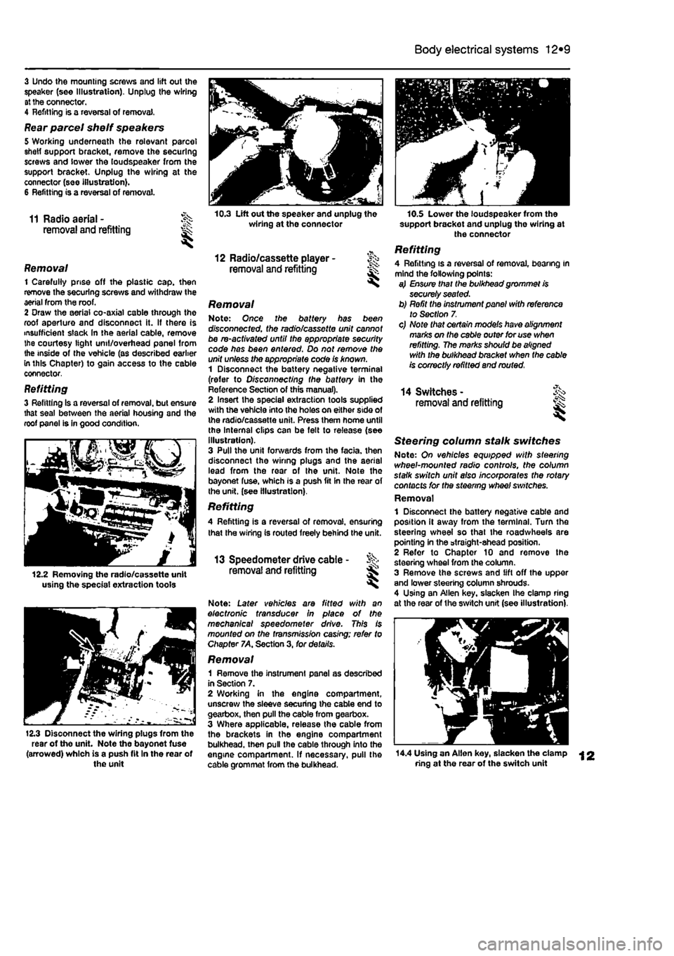
3 Undo the mounting screws and lift out the speaker (see Illustration). Unplug the wiring at the connector. 4 Refitting is a reversal of removal,
Rear parcel shelf speakers 5 Working underneath the relevant parcel shetf support bracket, remove the securing screws and lower the loudspeaker from the support bracket. Unplug the wiring at the connector (see illustration). 6 Refitting is a reversal of removal.
11 Radio aerial - J^s removal and refitting ^
Removal 1 Carefully prise off the plastic cap. then remove the securing screws and withdraw the aerial from the roof. 2 Oraw the aerial co-axial cable through the roof aperture and disconnect it. If there is insufficient slack In the aerial cable, remove the courtesy light unit/overhead panel from the inside of the vehicle (as described earlier in this Chapter) to gain access to the cable connector,
Refitting 3 Refitting Is a reversal of removal, but ensure that seal between the aerial housing and the roof panel is in good condition.
12.2 Removing the radio/cassette unit using the special extraction tools
12.3 Disoonnect the wiring plugs from the rear of the unit. Note the bayonet fuse (arrowed) which is a push fit In the rear of the unit
10.3 Lift out the speaker and unplug the wiring at the connector
12 Radio/cassette player -removal and refitting ^
Removal Note: Once the battery has been disconnected, the radio/cassette unit cannot be re-activated until the appropriate security code has been entered. Do not remove the unit unless the appropriate code Is known. 1 Disconnect the battery negative terminal (refer to Disconnecting the battery in the Reference Section of this manual). 2 Insert the special extraction tools supplied with the vehicle into the holes on either side of the radio/cassette unit. Press them home until the Internal clips can be felt to release (see illustration). 3 Pull the unit forwards from the facia, then disconnect the wiring plugs and the aerial lead from the rear of the unit. Note the bayonet fuse, which is a push fit in the rear of the unit, (see illustration).
Refitting A Refitting is a reversal of removal, ensuring that the wiring Is routed freely behind the unit.
13 Speedometer drive cable - % removal and refitting Ss ^
Note: Later vehicles are fitted with an electronic transducer in place of the mechanical speedometer drive. This is mounted on the fransm/ss/on casing; refer to Chapter 7A, Section 3, for details.
Removal 1 Remove the instrument panel as described in Section 7. 2 Working in the engine compartment, unscrew the sleeve securing the cable end to gearbox, then pull the cable from gearbox. 3 Where applicable, release the cable from the brackets in the engine compartment bulkhead, then pull the cable through into the engine compartment. If necessary, pull the cable grommet from the bulkhead.
10.S Lower the loudspeaker from the support brackot and unplug tho wiring at the connector
Refitting 4 Refitting is a reversal of removal, bearing in mind the following points: a} Ensure that the bulkhead grommet is securely seated. b) Refit the instrument panel with reference to Section 7. c) Note that certain models have alignment marks on the cable outer for use when refitting. The marks should be aligned with the bulkhead bracket when the cable is correctly refitted and routed.
14 Switches -removal and refitting ^
Steering column stalk switches Note: On vehicles equipped with sfeezing wheel-mounted radio controls, the column stalk switch unit also incorporates the rotary contacts for the steering wheel switches. Removal 1 Disconnect the battery negative cable and position it away from the terminal. Turn the steering wheel so that the roadwheeis are pointing in the straight-ahead position. 2 Refer to Chapter 10 and remove the steering wheel from the column. 3 Remove the screws and lift off the upper and lower steering column shrouds. 4 Using an Allen key. slacken Ihe clamp ring at the rear of the switch unit (see illustration),
14.4 Using an Allen key, slacken the clamp ring at the rear of the switch unit