Gas FIAT PUNTO 1999 176 / 1.G User Guide
[x] Cancel search | Manufacturer: FIAT, Model Year: 1999, Model line: PUNTO, Model: FIAT PUNTO 1999 176 / 1.GPages: 225, PDF Size: 18.54 MB
Page 53 of 225
2A*10 SOHC (8-valve) petrol engine in-car repair procedures
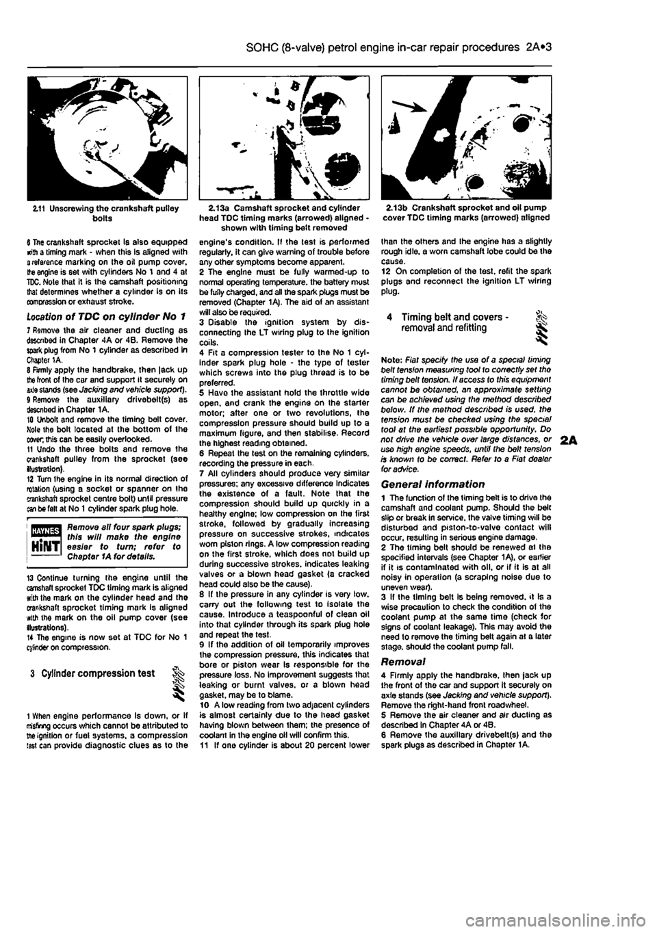
2.11 Unscrewing the crankshaft pulley bolts
6 Itae crankshaft sprocket Is also equipped •nth a timing mark - when this is aligned with 3relarence marking on the oil pump cover.
Hie
engine is set with cylinders No 1 and 4 at
TDC.
Note that it is the camshaft positioning that determines whether a cylinder is on its comcression or exhaust stroke.
Location
of TDC on cylinder No 1 7 Remove the air cleaner and ducting as descnbed in Chapter 4A or 4B. Remove the
spark
plug from No 1 cylinder as described in Chapter 1A. 8 Firmly apply the handbrake, then |ack up
the
front of the car and support it securely on iiia stands (see Jacking end vehicle support). 9 Remove the auxiliary drivebelt(s) as described in Chapter 1A. 10 Unbolt and remove the timing belt cover. Mole the bolt located at the bottom of the
coven
this can be easily overlooked. 11 Undo the three bolts and remove the crankshaft pulley from the sprocket (see {lustration). 12 Turn Ihe engine in its normal direction of rotation (using a socket or spanner on Ihe crankshaft sprocket centre bolt) until pressure an be felt at No
1
cylinder spark plug hole.
1 flfliyflg^ Remove all four spark plugs; "••"•1 this will make the engine HlNTl easier to turn; refer to Chapter 1A for details.
13 Continue turning the engine until the crahaft sprocket TDC timing mark is aligned with the mark on the cylinder head and the crankshaft sprocket timing mark is aligned with the mark on the oil pump cover (see ilustrations). 14 The engine is now set at TDC for No 1 cylinder on compression.
3 Cylinder compression test t ^
1 When engine performance Is down, or if misfiring occurs which cannot be attributed to tne ignition or fuei systems, a compression isst can provide diagnostic clues as to the
2.13a Camshaft sprocket and cylinder head TDC timing marks (arrowed) aligned -shown with timing belt removed engine's condition. II the test is performed regularly, it can give warning of trouble any other symptoms become apparent. 2 The engine must be fully warmed-up to normal operating temperature, the battery must be fufly charged, and all the spark plugs must be removed (Chapter 1A). The aid of an assistant will also be required. 3 Disable the ignition system by dis-connecting the LT wiring plug to the ignition coils. 4 Fit a compression tester to the No 1 cyl-inder spark plug hole - the type of tester which screws into the plug thread is to be preferred, 5 Have the assistant hold the throttle wide open, and crank the engine on the starter motor; after one or two revolutions, the compression pressure should build up to a maximum figure, and then stabilise. Record the highest reading obtained. 6 Repeat the lest on the remaining cylinders, recording the pressure in each. 7 All cylinders should produce very similar pressures; any excessive difference indicates the existence of a fault. Note that the compression should build up quickly in a healthy engine; low compression on the first stroke, followed by gradually increasing pressure on successive strokes, indicates worn piston rings. A low compression reading on the first stroke, which does not build up during successive strokes, indicates leaking valves or a blown head gasket (a cracked head could also be the cause). 8 If the pressure in any cylinder is very low. carry out the following test to isolate the cause. Introduce a teaspoonful of clean oil into that cylinder through its spark plug hole and repeat the test. 9 If the addition of oil temporarily improves the compression pressure, this indicates that bore or piston wear Is responsible for the pressure loss. No improvement suggests that leaking or burnt valves, or a biown head gasket, may be to blame. 10 A low reading from two adjacent cylinders is almost certainly due to the head gasket having blown between them; the presence of coolant in the engine oil will confirm this. 11 If one cylinder is about 20 percent lower
2.13b Crankshaft sprocket and oil pump cover TDC timing marks (arrowed) aligned
than the others and Ihe engine has a slightly rough idle, a worn camshaft lobe could be the cause. 12 On completion of the test, refit the spark plugs and reconnect the ignition LT wiring plug.
4 Timing belt and covers -removal and refitting ^
Note: Fiat specify the use of a special timing belt fens/on measuring toot to correctly set tho timing belt tension. If access to this equipment cannot be obtained, an approximate setting can be achieved using the method described below. It the method described is used, the tension must be checked using the special tool at the earliest possible opportunity. Do not drive the vehicle over large distances, or use high engine speeds, until the belt tension is known fo be correct. Refer to a Fiat dealer foradvSce.
General information 1 The function of the timing belt is to drive Ihe camshaft and coolant pump. Should the belt slip or break In service, the valve timing will be disturbed and piston-to-valvo contact will occur, resulting in serious engine damage, 2 The timing belt should be renewed ai the specified intervals (see Chapter 1A), or earlier if it is contaminated with oil. or if it is at all noisy in operation (a scraping noise due to uneven wear). 3 If the timing belt is being removed, it Is a wise precaution to check the condition of the coolant pump at the same time (check for signs of coolant leakage). This may avoid the need to remove the timing belt again at a later stage, should the coolant pump fall.
Removal 4 Firmly apply the handbrake, then jack up the front of the car and support it securely on axle stands (see Jacking and vehicle support). Remove the right-hand front road wheel. 5 Remove the air cleaner and air ducting as described in Chapter 4A or 46. 6 Remove the auxiliary drivebelt(s) and the spark plugs as described in Chapter 1A.
2A
Page 56 of 225
2A*10 SOHC (8-valve) petrol engine in-car repair procedures
6.3 Camshaft cover gasket
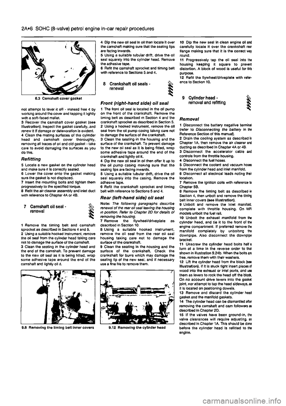
not attempt to lover it ofl • instead free >t by working around the cover and lapping it lightly with a soft-faced mallet, 3 Recover the camshaft covor gasket {see Illustration). Inspect the gasket carefully. And renew It If damage or deterioration is evident. 4 Clean the mating surfaces of the cylinder head and camshaft cover thoroughly, removing all traces of oil and old gasket - take care to avoid damaging the surfaces as you do this.
Refitting 5 Locate a new gasket on the cylinder head and make sure it Is correctly seated. 6 Lower the cover onto the gasket making sure the gasket is not displaced. 7 Insert Ihe mounting bolts and tighten them progressively to the specified torque. 8 Refit the air cleaner assembly and inlet duct with reference to Chapter 4A or 48.
7 Camshaft oil seal • renewal I
1 Remove the timing beft and camshaft sprocket as described in Sections 4 and 5, 2 Using a suitable hooked Instrument, remove the oil seal from the cylinder head taking care not to damage the surface of (he camshaft. 3 Clean the seating in the cylinder head and the end of the camshaft. To prevent damage to the new olf seal as it is being fitted, wrap some adhesive tape around the end of the camshaft and lightly oil it.
4 Dip the new oil seal In oil then locate it over the camshaft making sure that the sealing lips are facing inwards, 5 Using a suitable tubular drift, drive the oil seal squarely Into the cylinder head. Remove the adhesive tape. 8 Refit the camshaft sprocket and liming belt wtth reference to Sections 5 and 4.
8 Crankshaft oil seals - ^ renewal S
Front (right-hand side) oil seal 1 The fronl oil seal is located in tho oil pump on the front of the crankshaft. Remove the timing belt as described in Section 4 and the crankshaft sprocket as described in Section 5. 2 Using a hooked instrument, remove the oil seal from the oil pump casing taking care not to damage the surface of the crankshaft. 3 Clean Ihe seating in the housing and the surface of the crankshaft. To prevent damage to the new oil seal as it is being fitted, wrap some adhesive tape around the end of the crankshaft and lightly oil it. 4 Dtp the new oil seal In oil then offer It up 1o the oil pump casing making sure that tho sealing lips are facing Inwards. G Using a suitable tubular drift, drive the oil seal squarely into the casing. Remove the adhesive tape. 6 Refit the crankshaft sprocket and timing belt with reference to Sections S and 4.
Rear {left-hand side) oil seal Note: The following paragraphs describe renewal of the rear oil seal leaving the housing in position. Refer to Chapter 2D for details of removing the housing. 7 Remove the fiywheel/drlveplate as described in Section 10. 8 Using a suitable hooked instrument, remove the oil seal from the rear oil seat housing taking care not to damage the surface of Ihe crankshaft. 9 Clean the seating In the nousing and the surface of the crankshaft. Check the crankshaft for burrs which may damage the sealing lip of the new seal, and If necessary use a fine file to remove them,
10 Dip the new seal In clean engine oil and carefully locate it over the crankshaft rear flange making sure that It is the correct way round. 11 Progressively tap the oil seal Into the housing keeping It square to prevent distortion. A block of wood is useful for this purpose. 12 Refit the fiywheet/drlvepiate with refer-ence to Section 10.
9 Cylinder head -removal and refitting I
i Removing the timing belt inner covers 9.12 Removing the cylinder head
Removal 1 Disconnect the battery negative termine! (refer to Disconnecting the battery In the Reference Section of this manual). 2 Drain the cooling system as described In Chapter 1A. then remove the air cleaner and ducting as described in Chapter 4A or 48. 3 Disconnect the accelerator cable and controls from the throttle housing. 4 Disconnect the fuel hoses. 5 Disconnect the coolant and vacuum hoses from the cylinder head and inlet manifold. 6 Disconnect all electrical leads noting their location. 7 Remove the Ignition colls with reference to Chapter 58. 8 Remove the timing belt as described in Section 4, then unbolt end remove the timing belt inner covers (see Illustration). 9 Unbolt and remove the Inlet manifold, complete with throttle housing. On MPI models unbolt the fuel rail. 10 Unbolt the exhaust manifold from th» cylinder head, and tie it to the front of tto engine compartment. If preferred remove the manifold completely by unbolting Ihe downpipe. Also disconnect iha downpipe bracket. 11 Unscrew the cylinder head bolts hall a turn at a time in the reverse order to thai shown In illustration 9.24b. When the bolts in free, remove them wtth their washers. 12 Lift the cylinder head from Ihe block (see Illustration), if It is stuck tight Insert pieces
of
wood Into the exhaust or Inlet ports, and use them as levers to rock the head off the block. On no account drive levers into the gasket joint, nor attempt to tap the head sideways,
as
It Is located on positioning dowels. 13 Remove and discard the cylinder heed gasket and the manifold gaskets. 14 The cylinder head can be dismantled after removing the camshaft and cam followers as described in Chapter 2D. 15 If the valves have been ground-in, the valve clearances will require adjusting, as described In Chapter 1A. This should be dons before the cylinder head is refitted to the engine.
Page 57 of 225
2A*10 SOHC (8-valve) petrol engine in-car repair procedures
Preparation for refitting 16 The mating faces of the cylinder head and cylinder block must be perfectly clean before
refitting
the head. Use a hard plastic or wooden scraper to remove all traces of gasket and carbon; also clean the piston crowns. Take padicular care when cleaning the piston crowns as the soft aluminium alloy is easily damaged. Make sure that the carbon is not afowed to enter the oil and water passages -Ihs is particularly important for the lubrication
system, as
carbon could block the oil supply to
Ihe
engine's components. Using adhesive tape
and
paper, seal the water, oil and bolt holes in tf« cylinder block. To prevent carbon entering twgap between the pistons and bores, smear
a
iittte grease in the gap. After cleaning each piston, use a small brush to remove all traces of grease and carbon from the gap, then wipe away the remainder with a clean rag. Clean all
ttie pistons
in the same way. 17 Check the mating surfaces of the cylinder block and the cylinder head for nicks, deep scratches and other damage. If slight, they may be removed carefully with a file, but if (xcassive, machining may be the only alternative to renewal. If warpage of the Cytodar head gasket surface is suspected, use a straight-edge to check it for distortion.
Refer
to Part 0 of this Chapter if necessary. 18 Check the condition of the cylinder head
MRS.
and particularly their threads, whenever
they are
removed. Wash the bolts In a suitable solvent, and wipe them dry. Check each bolt for any sign of visible wear or damage, renewing them if necessary.
Refitting 18 Before refitting Ihe assembled cylinder head, make sure that the head and block mating surfaces are perfectly clean, and that
the
bolt holes in the cylinder block have been
mopped
out to clear any oil. 20 Check that the camshaft and crankshaft sprocket timing marks are still aligned with tteir respective cylinder head and oil pump covtr marks as described in Section 2. 21 The new gasket should not be removed from its nylon cover until required for use. Fit
the
gasket dry, and make sure that the mating surfaces on the head and block are perfectly dean.
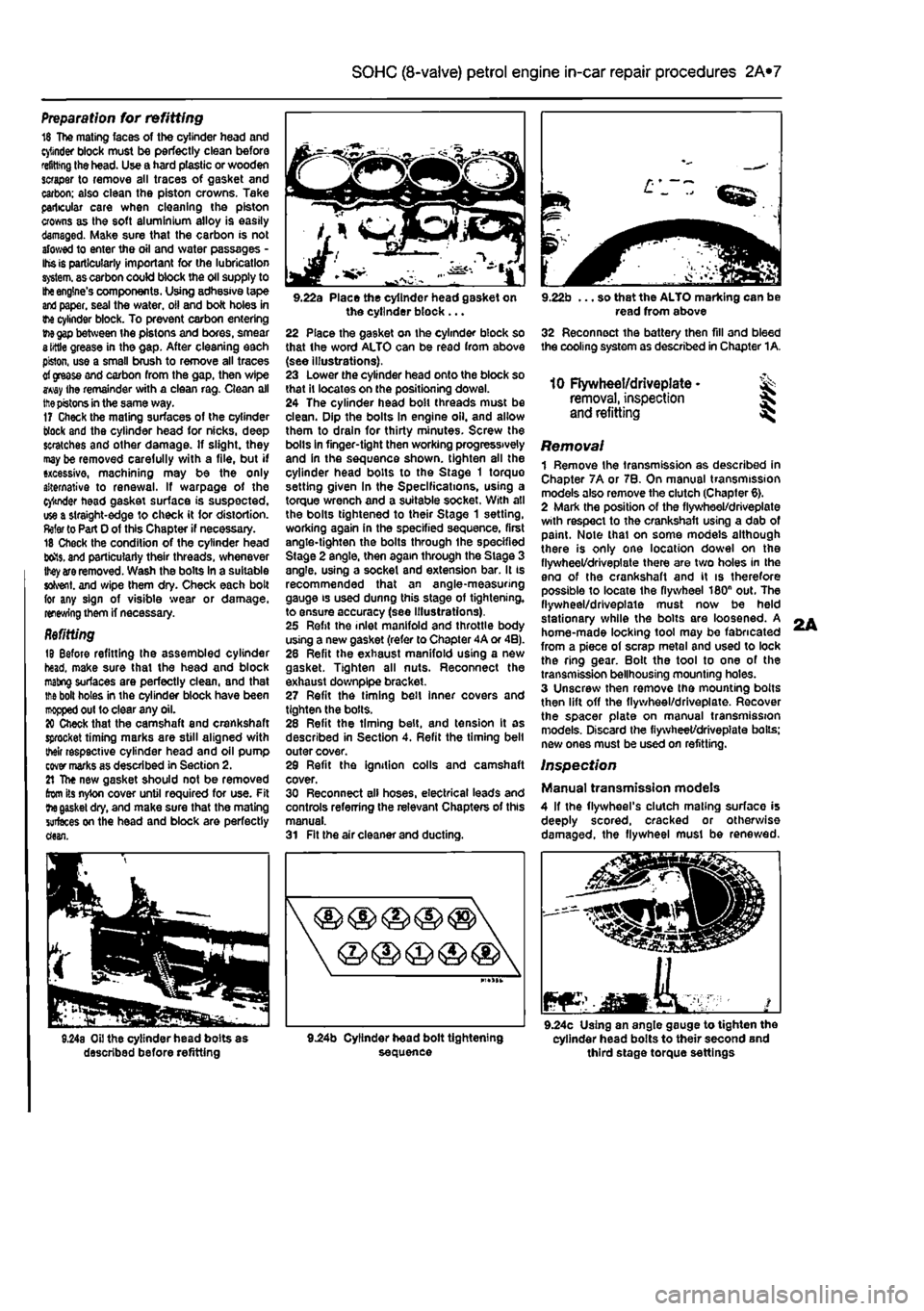
9.22a Place the cylinder head gasket on the cylinder block ... 22 Place the gasket on the cylinder block so that the word ALTO can be read from above (see illustrations). 23 Lower the cylinder head onto the block so that It locates on the positioning dowel. 24 The cylinder head bolt threads must be clean. Dip the bolts In engine oil. and allow them to drain for thirty minutes. Screw the bolls in finger-tight then working progressively and in the sequence shown, tighten all the cylinder head bolts to the Stage 1 torque setting given In the Specifications, using a torque wrench and a suitable socket. With all the bolts tightened to their Stage 1 setting, working again in the specified sequence, first angle-tighten the bolts through ihe specified Stage 2 angle, then again through the Stage 3 angle, using a socket and extension bar. It is recommended that an angle-measuring gauge is used dunng this stage of tightening, to ensure accuracy (see Illustrations). 25 Refit the inlet manifold and throttle body using a new gasket (refer to Chapter 4A or 4B). 28 Refit the exhaust manifold using a new gasket. Tighten all nuts. Reconnect the exhaust downplpe bracket. 27 Refit the timing belt inner covers and tighten the bolls. 28 Refit the timing belt, and tension It as described in Section 4. Refit the timing belt outer cover. 29 Refit the ignition colls and camshaft cover. 30 Reconnect all hoses, electrical leads and controls referring the relevant Chapters of this manual. 31 Fit the air cleaner and ducting.
9.22b ... so that the ALTO marking can be read from above 32 Reconnect the battery then fill and bleed the cooling system as described in Chapter 1A.
10 Flywheel/driveplate • ^ removal, inspection
and
refitting ^
Removal 1 Remove the transmission as described in Chapter 7A or 7B. On manual transmission models also remove the clutch (Chapter 6). 2 Mark the position of the flywheel/driveplate with respect to the crankshaft using a dab of paint. Note thai on some models although there is only one location dowel on the flywheel/driveplate there are two holes in the eno of the crankshaft and it is therefore possible to locate Ihe flywheel 180n out. The flywheel/driveplate must now be held stationary while the bolts are loosened. A home-made locking tool may be fabricated from a piece of scrap metal and used to lock the ring gear. Bolt the tool to one of the transmission bellhousing mounting holes. 3 Unscrew then remove the mounting bolts then lift off the flywheel/driveplate. Recover the spacer plate on manual transmission models. Discard the fiywheet/drivepiate boils; new ones must be used on refitting.
Inspection
Manual transmission models 4 If the flywheel's clutch mating surface is deeply scored, cracked or otherwise damaged, the flywheel must be renewed.
JEaMKA. mar 9.24c Using an angle gauge to tighten the cylinder head bolts to their second and third stage torque settings
L
Page 59 of 225
2A*10 SOHC (8-valve) petrol engine in-car repair procedures
require cutting with a sharp Knife to release
the sump.
Clean away all old gasket material. Refitting
5
Wwn refitting, a bead of RTV silicone nsiant gasket 3 mm in diameter should be applied lo the sump flange. Fit the sump, screw in tha fixing screws and tighten to the spscabed torque. Note the flange end fixing
nuts
(see illustrations).
6
'//ait one hour for the gasket compound to henjai before filling with engine oil. 7 Refit the flywheel housing cover plate and tohaust system front pipe.
8
lower the vehicle to the ground and fill the eng'rewith oil (see Chapter 1A). Check the oil
fevai
alter running the engine for a few minutes.
13 Oil
pump and pick-up tube - >>>
removal,
inspection and ^ refitting ^
Removal 1 Drain tho engine oil and remove the sump adsswibed in Section 12.
%
Unscrew and remove the oil filter cartridge .
(see
Chapter 1A|. 3 Remove the timing belt as described In
Section A.
4
Lock
the crankshaft against rotat>on either by tfacng a block of wood between a crankshaft wb and the inside of the crankcase, or by jjmning the flywheel starter ring gear with a
lutabfe
tool.
I3v8a Removing the oil pump pressure relief valve
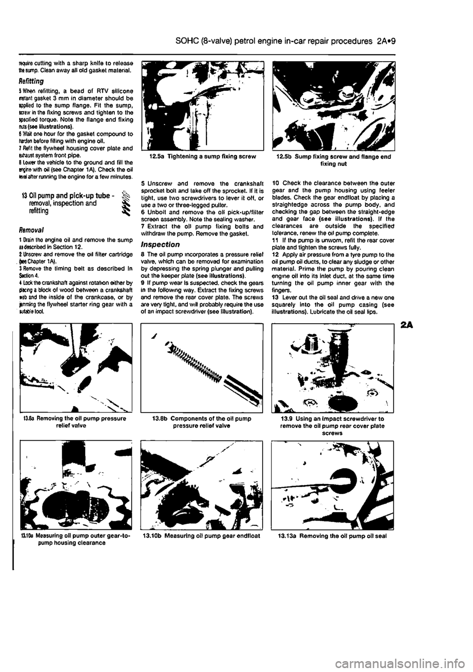
12.5a Tightening a sump fixing screw
5 Unscrew and remove the crankshaft sprocket boll and take off the sprocket. If it is tight, use two screwdrivers to lever it off, or use a two or three-legged puller. 6 Unbolt and remove the oil pick-up/filter screen assembly. Note the sealing washer. 7 Extract the oil pump fixing bolts and withdraw the pump. Remove the gasket.
Inspection 8 The oil pump incorporates a pressure relief valve, which can be removed for examination by depressing the spring plunger and pulling out the keeper plate (see illustrations). 9 If pump wear Is suspected, check the gears in the following way. Extract the fixing screws and remove the rear cover plate. The screws are very tight, and will probably require the use of an impact screwdriver (see illustration).
pressure relief valve
12.5b Sump fixing screw and flange end fixing nut
10 Check the clearance between the outer gear and the pump housing using feeler blades. Check the gear endtloat by placing a straightedge across the pump body, and checking the gap between the straight-edge and gear face (see illustrations). If the clearances are outside the specified tolerance, renew the oil pump complete. 11 If the pump is unworn, refit the rear cover plate and tighten the screws fully. 12 Apply air pressure from a tyre pump to the oil pump oil ducts, to clear any sludge or other material. Prime the pump by pouhng clean engine oil into its inlet duct, at the same time turning the oil pump inner gear with the fingers. 13 Lever out the oil seal and drive a new one squarely into the oil pump casing (see illustrations). Lubricate the oil seal lips.
13.9 Using an impact screwdriver to remove the oil pump rear cover pfate screws
13,19s Measuring oil pump outer gear-to- 13.10b Measuring oil pump gear endtloat pump housing clearance
Page 60 of 225
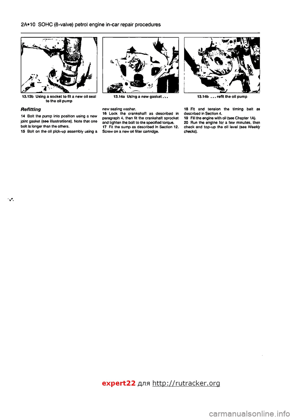
2A*10 SOHC (8-valve) petrol engine in-car repair procedures
13.13b Using a socket to lit a new oil sea! to the oil pump
Refitting 14 Bolt the pump into position using a new joint gasket (see illustrations). Note that on© bolt Is longer than the others. 15 Bolt on the oil pick-up assembly using a
13.14a Using a new gasket. ..
new sealing washer. 16 Lock the crankshaft as described in paragraph 4, then fit the crankshaft sprocket and bghlen the bolt to the specified torque. 17 Fit the sumpaa described in Section 12. Screw on a new oil filter cartridge.
13.14b ... reftt the oil pump
18 Fit and tension the timing belt as described in Section 4. 19 Fill the engine with oil (see Chapter 1A>. 20 Run the engine for a few minutes, then check and top-up the oil level (see Weekly checks).
expert22 f
a http://rutracker.org
Page 64 of 225
2B*4 DOHC (16-valve) petrol engine in-car repair procedures
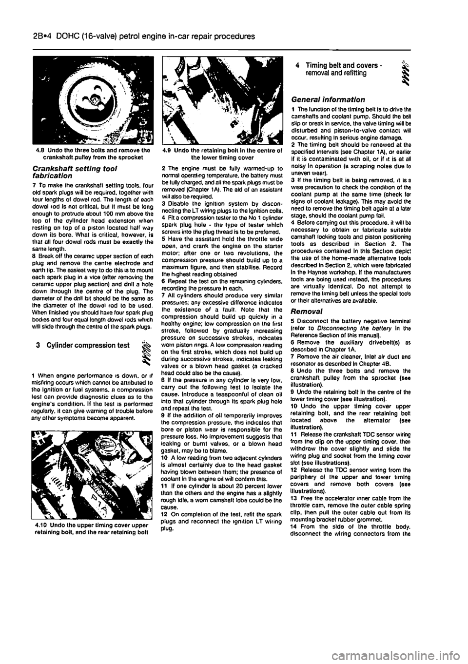
4.8 Undo three bolts and romove tho crankshaft pulley from the sprocket
Crankshaft setting toot fabrication 7 To make Ihe crankshafl setting tools, four old spark plugs will be required, together with four lengths of dowel rod. The length of each dowel rod is not critical, bul It must be long enough to protrude about 100 mm above the top of the cylinder head extension when resting on top of a piston located half way down its bore. What is critical, however, is that all four do wo I rods must be exactly the same length. 8 Break off the ceramic upper section of each plug and remove the centre electrode and earth tip. The easiest way to do this is to mount each spark plug in a vice (attar removing the ceramic uppor plug section) and drill a hole down through ihe centre of the plug. The diameter of Ihe drill bit should be the same as Ihe diameter of Ihe dowol rod to be used. When finished you should have four spark plug bodies and four equal length dowel rods which will slide through the centre of the spark plugs.
3 Cylinder compression test
1 When engine performance is down, or it misfiring occurs which cannot be attnbuted to the Ignition or fuel systems, a compression test can provide diagnostic clues as to the engine's condition. If the lest is performed regularly, it can give warning of trouble bofore any other symptoms become apparent.
4.10 Undo the upper timing cover upper retaining bolt, and the rear retaining boll
4.9 Undo the retaining bolt in the centre of the lower timing cover
2 The engine must be fully warmed-up to normal operxrtrfjg temperature, the battery must be fully charged, and all the spark plugs muse be removed (Chapter 1A>. The aid of an assistant wilt also be required. 3 Disable the ignition system by discon-necting the LT wiring plugs to the Ignition coils. 4 Fit a compression tester to the No t cylinder spark plug hole • the type of tester which screws into the plug thread is to be preferred. 5 Have the assistant hold the throttle wide open, and crank the engine on the starter motor; after one or two revolutions, the compression pressure should build up to a maximum figure, and then stabilise. Record the h.ghest reading obtained 6 Repeat the test on the remaining cylinders, recording Ihe pressure in each. 7 All cylinders should produce very similar pressures; any excessive difference indicates Ihe existence of a fault. Note that the compression should build up quickly in a healthy engine; low compression on (he first stroke, followed by gradually increasing pressure on successive strokes, indicates worn piston rings. A low compression reading on the first stroke, which does not build up during successive strokes, indicates leaking valves or a blown head gasket (a cracked head could also be tho cause). 6 If the pressure in any cylinder is very low, carry out the following test to isolate the cause. Introduce a teaspoonful of dean oil into that cylinder through its spark plug hole and repeal the lest. 9 If the addition of oil temporarily improves the compression pressure, this indicates that bore or piston wear is responsible for the pressure loss. No improvement suggests that leaking or burnt valves, or a blown head gasket, may be to blame. 10 A low reading from two adjacent cylinders is almost certainly due to the head gasket having blown between Ihem; the presence of coolant in the engine oil will confirm this. 11 If one cylinder is about 20 percent lower than the others and the engine has a slightly rough idle, a worn camshaft lobe could be the cause. 12 On completion of the test, refit the spark plugs and reconnect the ignition LT wiring plug.
4 Timing belt and covers -removal and refitting §
General information 1 The luncUon of the timing belt Is to drive the camshafts and coolant pump. Should the bell slip or creak in service, the valve timing will be disturbed and piston-to-valve contact wiu occur, resulting in serious engine damage. 2 The timing belt should be renewed at the specified Intervals (see Chapter 1A), or earlier If It is contaminated with oil, or if it is at all noisy In operation (a scraping noise due to uneven wear}. 3 If the timing belt is being removed, it is
a
wise precaution to check the condition of the coolam pump at the same time (oheck for signs of coolant leakage). This may avoid the need to remove the timing belt again at a later stage, should the coolant pump fail. 4 Before carrying out this procedure, it will be necessary to obtain or fabricate suitable camshaft locking tools and piston positioning tools as described in Section 2. The procedures contained In this Section depict the use of the home-made alternative tools described in Section 2. which were fabricated In the Haynes workshop. If the manufacturers tools are being used instead, the procedures are virtually identical. Oo not attempt to remove the timing bell unless the special totfs or their alternatives are available.
Removal 5 Disconnect the battery negative terminal (refer to Disconnecting the battery in the Reference Section of Ihis manual). 6 Remove the auxiliary drivebelt(s) as described In Chapter 1A. 7 Remove the air cleaner, Inlet air duct and resonator as desenbed In Chapter 4B. 8 Undo the three bolts and remove the crankshaft pulley from the sprocket (see illustration). 9 Undo the retaining bolt In the centre of the lower liming cover (see illustration). 10 Undo tho uppor timing cover upper retaining bolt, and the rear retaining bolt located above the alternator (see illustration). 11 Release the crankshaft TDC sensor wiring from the clip on the upper timing cover, then withdraw the cover slightly and slide Ihe wiring plug and socket from the liming cover slot (see illustrations). 12 Release the TDC sensor wiring from the periphery ol the upper and fower timing covers and remove both covers (see Illustrations). 13 Free the accelerator inner cable from the throttle cam, remove the outer cable spring dip, then pull the outer cable out from its mounting bracket rubber grommet. 14 From the side of the throttle body, disconnect the wiring connectors from the
Page 68 of 225
2B*8 DOHC (16-valve) petrol engine in-car repair procedures
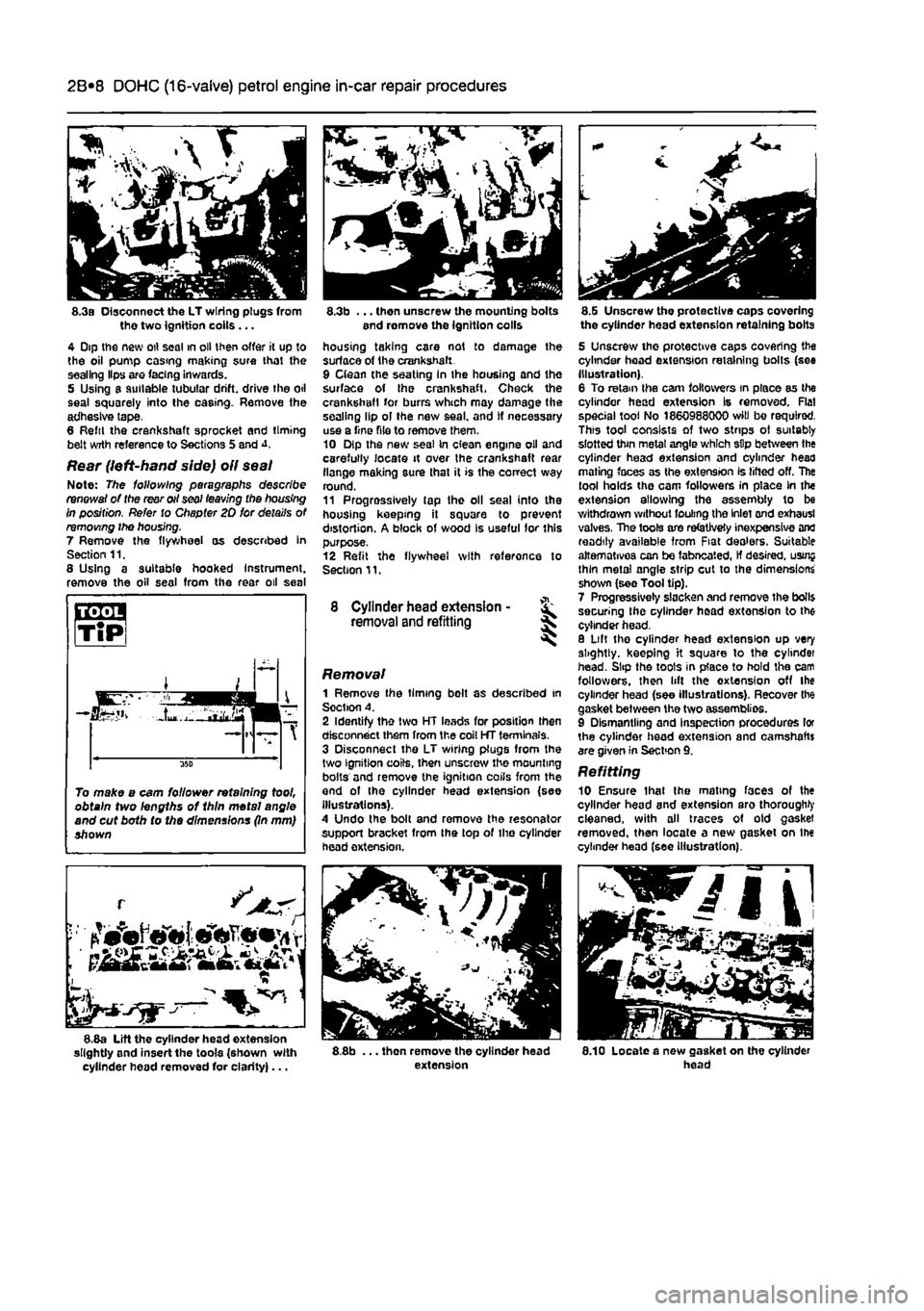
8.3a Disconnect the LT wiring plugs from the two Ignition coils ... 4 Dip the new oil seal in oil then offer it up to the oil pump casing making sure that the sealing Hps are facing inwards. 5 Using a suitable tubular drift, drive the oil seal squarely into the casing. Remove the adhesive tape, 8 Reftl the crankshaft sprocket and timing belt wrth reference to Sections 5 and
Rear (left-hand side) oil seal Note: The following paragraphs describe renewal of the rear oil seal leaving the housing in position. Refer to Chapter 20 for details of removing ihe housing. 7 Remove the flywheel as described In Section 11. 8 Using a suitable hooked Instrument, remove the oil seal from the rear oil seal
L •
~ 1 8.8a Lift the cylinder head extension slightly and insert the tools {shown with cylinder head removed for clarity)...
8.3b ... then unscrew the mounting bolts end romove the ignition colls housing taking care not to damage the surface of the crankshaft. 9 Clean the seating In the housing and the surface of Ihe crankshaft. Check the crankshaft for burrs which may damage the sealing lip ol Ihe new seal, and If necessary use a Tine file to remove them. 10 Dip the new seal In clean engine oil and carefully locate it over Ihe crankshaft rear flange making sure that it is the correct way round. 11 Progressively tap the oil seal into the housing keeping it square to prevent distortion. A block of wood Is useful for this purpose. 12 Refit the flywheel with reference to Section 11,
8 Cylinder head extension -removal and refitting ^
Removal 1 Remove the timing bolt as described in Soction A. 2 Identify the two HT leads for position then disconnect them from the coil HT terminals. 3 Disconnect the LT wiring plugs from the two ignition coils, then unscrew the mounting bolts and remove the ignition coils from the and of the cylinder head extension {see illustrations). A Undo the bolt and remove the resonator support bracket from Ihe top of the cylinder head extension,
8.8b ... thon remove the cylinder head extension
8.G Unscrew tho protective caps covering the cylinder head extension retaining bolts
5 Unscrew the protective caps covering the cylinder head extension retaining bolts (see Illustration). 6 To retain the cam followers in place as the cylinder head extension Is removed. Flat special tool No 1860988000 will bo required. This tool consists of two strips ol suitably slotted thin metal angle which sDp between the cylinder head extension and cylinder head mating faces as the extension Is lifted off. The tool holds the cam followers in place in the extension allowing the assembly to be withdrawn without fouling the Inlet and exhausl valves, The tools are refetJvety inexpensive and readily available from Fiat dealers. Suitable alternatives can be fabneated, If desired, usrnj thin metal angle strip cut to the dimensions shown (see Tool tip). 7 Progressively slacken and remove the boll$ securing the cylinder head extension to the cylinder head. 8 Lilt tho cylinder head extension up very slightly, keeping it square to the cylindei head. Slip the toots in place to hold the cam followers, then lift the extension off the cylinder head (see illustrations). Recover the gasket between the two assemblies. 9 Dismantling and Inspection procedures lor the cylinder head extension and camshafts are given in Section 9. Refitting 10 Ensure thai Ihe mating faces of the cylinder head and extension aro thorough^ cleaned, with all traces of old gasket removed, then locate a new gasket on Ihe cylinder head (see Illustration).
8.10 Locate a new gasket on the cylinder head
To make a cam follower retaining tool, obtain two lengths of 1hln metal angle and cut both to the dimensions (In mm) shown
Page 69 of 225
2B*9 DOHC (16-valve) petrol engine in-car repair procedures
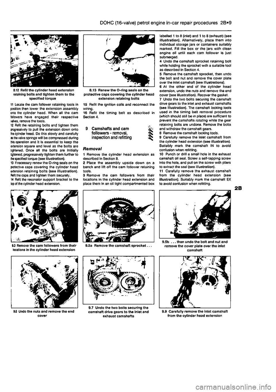
8.12 Rofit tho cylinder head extension retaining bolts and tighten them to tho specified torque 11 Locate the cam follower retaining tools in position Ihen lower the extension assembly onto the cylinder head. When all the cam followers have engaged their respective valves, remove the tools. 12 Refit tho retaining bolts and tighten them progressively to pull the extension down onto
the
cylinder head. Do this slowly and carefully
as the
vaivo springs will be compressed during Ihfs operation and it is essential to keep the extension square and level as the bolts are lightened. Once all the bolts are Initially Bghloned. progressively tighten them further to
the specified
torque (see illustration). 13 If necessary renew the O-rlng seals on the protective caps covering the cylinder head extension retaining bolts (see illustration).
Refit
the caps and tighten them securoly. 14 Refit the resonator support bracket to the
Icp of
the cylinder head extension.
8.13 Renew the O-ring seals on the protective caps covering the cylinder head extension retaining bolts 15 Refil the ignition coils and reconnect Ihe wiring. 16 Refit the timing belt as described in Section 4.
9 Camshafts and cam ^ followers -
removal,
S inspection and refitting ^
Removal 1 Remove the cylinder head extension as described in Section 8. 2 Place the assembly upside down on a bench and lift off the cam follower retaining tools, 3 Remove the cam followers from their locations In the cylinder head extension and place them In an oil tight compartmented box
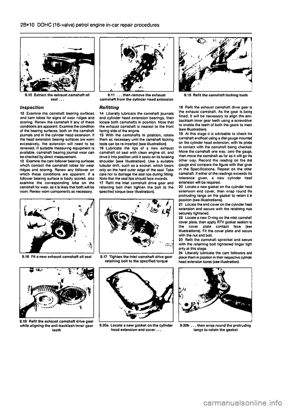
labelled 1 to 8 (inlet) and 1 to 8 (exhaust) (see illustration). Alternatively, place them into individual storage jars or containers suitably marked. Fill the box or the jars with clean engine oil until each cam follower is just submerged, 4 Undo the camshaft sprocket retaining bolt while holding the sprocket with a suitable tool as described In Section 4. 5 Remove the camshaft sprocket, then undo the bolt and nut and remove the cover plate over the inlet camshaft (see Illustrations), 6 At the other end of the cylinder head extension, undo the nuts and remove the end cover (soe Illustration). Recover the gasket. 7 Undo the two bolts securing the camshaft drive gears to the inlet and exhaust camshafts (see illustration). The camshaft locking tools used in the timing belt removal procedure (which should still be in place) are sufficient to prevent the camshafts rotating while the gear retaining bolts are undone. Remove the bolts and withdraw the camshaft gears. 8 Remove the camshaft locking tools. 9 Carefully remove the Inlet camshaft from the cylinder head extension (see illustration). Suitably mark the camshaft IN to avoid confusion when refitting. 10 Punch or drill a small hole in the exhaust camshaft oil seal. Screw a self-tapping screw into the hole, and pull on the screw with pliers to extract the seat (soe illustration). 11 Carefully remove Ihe exhaust camshaft from the cylinder head extension (soe illustration). Suitably mark the camshaft EX to avoid confusion when refitting.
JJ Remove the cam followers from their 9.5a Remove the camshaft sprocket... locations in the cylinder head extension
9.5b ... then undo the bolt and nut and remove the cover plate over tho inlet camshaft
9.6 Undo the nuts and remove the end cover
9.7 Undo the two bolts securing the camshaft drive gears to the inlet and exhaust camshafts 9.9 Carefully remove tho Inlet camshaft from the cylinder head extension
Page 70 of 225
2B*10 DOHC (16-valve) petrol engine in-car repair procedures
9.10 Extract the exhaust camshaft oil seal...
Inspection 12 Examine the camshaft bearing surfaces and cam lobes for signs of wear ridges and scoring. Renew ihe camshaft If any of these conditions are apparent. Examine the condition of the bearing surfaces, both on the camshaft journals and in the cylinder head extension. If the head extension beanng surfaces are worn excessively, the extension will need to be renewed. If suitable measuring equipment Is available, camshaft bearing journal wear can be checked by direct measurement. 13 Examine the cam follower bearing surfaces which contact the camshaft lobes for wear ridges and scoring. Renew any follower on which these conditions are apparent. If a follower bearing surface is badty scored, also examine the corresponding lobe on the camshaft for wear, as it is likely that both will be worn. Renew worn components as necessary.
9.11 ... then remove the exhaust camshaft from the cylinder head extension
Refitting 14 Liberally lubricate the camshaft journals and cylinder head extension bearings, then locate both camshafts in position Note that the exhaust camshaft is nearest to the front facing side of the engine. 15 With the camshafts In position, rotate them as necessary until the camshaft locking tools can be re-inserted (see illustration). 16 Lubricate the Hps of a new exhaust camshaft oil seal with clean engine oil, and drive It into position until it seats on its locating shoulder (see Illustration). Use a suitable tubular drifl, such as a socket, which bears only on the hard outer edge of the seaJ. Take care not to damage the seal lips during fitting. Noto that the seal lips should face inwards. 17 Refit the Inlet camshaft drive gear and retaining boll then tighten the bolt to the specified torque (see illustration).
9.16 Fit a new exhaust camshaft oil seal M7 Tighten the Inlet camshaft drive gear retaining bolt to the specified torque
9.15 Refit the camshaft locking tools
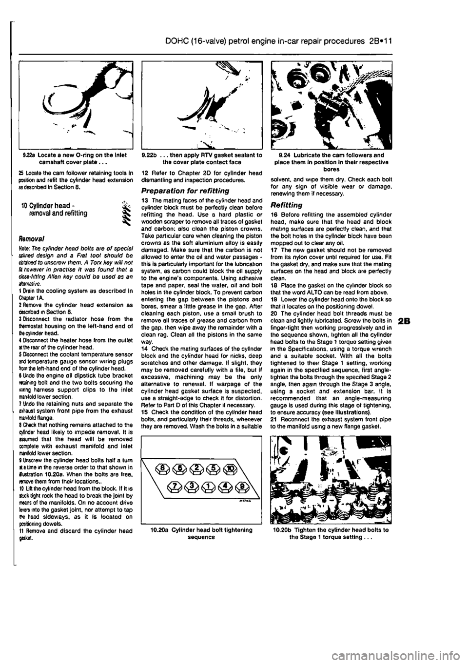
18 Refit the exhaust camshaft drive gear to the exhaust camshaft. As the gear is being fitted, It will be necessary to align the anti» backlash inner gear teeth using a screwdriver to enable the teeih of both Ihe gears to mes-i (see Illustration). 19 At this stage it is advisable lo check tie camshaft endfloat using a dial gauge mounted on the cylinder head extension, with its probe in contact with Ihe camshaft being checked Move the camshaft one way. zero the gauge, then move the camshaft as far as it will go ihe other way. Record the reading on the dial gauge and compare the figure with that given in the Specifications. Repeat on the other camshaft. If either of the readings exceeds the tolerance given, a new cylinder head extension will be required. 20 Locate a new gasket on the cylinder head extension end cover, then wrap round the protruding tangs on Ihe gasket to retain it in position (see Illustrations). 21 Locate the end cover on the cylinder heed extension and secure with the retaining nuts securely tightened. 22 Locate a new O-ring on the inlet camshaft cover plate, then apply RTV gasket sealant lo the cover plate contact face (see Illustrations), Fit tho cover plate and secure with the nut and bolt. 23 Refit the camshaft sprocket and secure with the retaining bolt tightened finger tight only at this stage. 24 Liberally lubricate the cam followers and piece them in position in their respective cylinder head extension bores (see illustration),
9.18 Refit the exhaust camshaft drive gear white aligning the anti-backlash Inner gear teeth 9.20a Locate a new gasket on the cylinder head extension end cover... 9.20b ... then wrap round the protruding tangs to retain the gaskel
Page 71 of 225
DOHC (16-valve) petrol engine in-car repair procedures 2B*11
camshaft cover plate... 25 Locate the cam follower retaining tools in position and refit the cylinder head extension
as
described In Section 8.
10
Cylinder head - &
removal and
refitting S
Removal Note; The cylinder head bolts are of special
sekned
design and a Fiat tool should be
obtained
to unscrew them. A Ton key will not
JSt however
in practise It was found that a dose-httlng Alien key could be used as an itemative. 1 Drain the cooling system as described in Chapter 1A. 2 Remove the cylinder head extension as oescAbed
m
Section 8. 3 Disconnect the radiator hose from the thermostat housing on the left-hand end of
Ihe
cylinder head. 4 Disconnect the heater hose from the outlet
at the
rear of the cylinder head. 5 Disconnect the coolant temperature sensor md temperature gauge sensor wiring plugs
torn
the left-hand end of the cylinder head. 9 Undo the engine oil dipstick tube bracket retaining bolt and the two bolts securing the wing harness support clips to the inlet marriold lower section. 7 Undo Ihe retaining nuts and separate the ixhaust system front pipe from the exhaust manifold flange.
8
Check that nothing remains attached to the cinder head likely to impede removal. It Is assumed that the head will be removed complete with exhaust manifold and inlet manifold lower section. 9 Unscrew the cylinder head bolts half a turn K
e
time in the reverse order to that shown in (lustration 10.20a. When the bolts are free. «mwe them from their locations.. Id Lift the cylinder head from the block. If it is stuck tight rock the head to break the joint by mans of the manifolds. On no account drive
levers
into the gasket Joint, nor attempt to tap tf« head sideways, as it is located on positioning dowels. 11 Remove and discard the cylinder head gasket.
JK'
l^. 9.22b ... then apply RTV gasket sealant to the cover plate contact face 12 Refer to Chapter 20 for cylinder head dismantling and inspection procedures. Preparation for refitting 13 The mating faces of the cylinder head and cylinder block must be perfectly dean before refitting the head. Use a hard plastic or wooden scraper to remove all traces of gasket and carbon; also clean the piston crowns, Take particular care when cleaning the piston crowns as the soft aluminium alloy is easily damaged. Make sure that the carbon is not allowed to enter the oil and water passages -this Is particularly important for the lubncahon system, as carbon could block the oil supply to the engine's components. Using adhesive tape and paper, seal the water, oil and bolt holes in the cylinder block. To prevent carbon entering the gap between the pistons and bores, smear a little grease In the gap. After cleaning each piston, use a small brush to remove all traces of grease and carbon from the gap. then wipe away the remainder with a clean rag. Clean all the pistons in the same way. 14 Check the mating surfaces of the cylinder block and the cylinder head for nicks, deep scratches and other damage. If slight, they may be removed carefully with a file, but If excessive, machining may be the only alternative to renewal. If warpage of the cylinder head gasket surface Is suspected, use a straight-edge to check it for distortion. Refer to Part 0 of this Chapter if necessary. 15 Check the condition of the cylinder head bolts, and particularly their threads, whenever they are removed. Wash the bolts In a suitable
sequence
9.24 Lubricate the cam followers and place them in position in their respective bores solvent, and wipe them dry. Check each bolt for any sign of visible wear or damage, renewing them if necessary.
Refitting 18 Before refitting the assembled cylinder head, make sure that the head and block mating surfaces are perfectly clean, and that the bolt holes in the cylinder block have been mopped out to clear any oil, 17 The now gasket should not be removed from its nylon cover until required for use. Fit Ihe gasket dry, and make sure that the mating surfaces on the head and block are perfectly clean. 18 Place the gasket on the cylinder block so that the word ALTO can be read from above. 19 Lower the cylinder head onto the block so that it locates on the positioning dowel. 20 The cylinder head bolt threads must be clean and lightly lubricated. Screw the bolts in finger-tight then working progressively and in the sequence shown, lighten all the cylinder head bolts to the Stage 1 torquo setting given In the Specifications, using a torque wrench and a suitable socket. With all the bolts tightened to their Stage 1 setting, working again in the specified sequence, first angle-tighten the bolts through the specified Stage 2 angle, then again through the Stage 3 angle, using a socket and extension bar. It Is recommended that an angle-measuring gauge Is used during this stage ot tightening, to ensure accuracy (see Illustrations). 21 Reconnect the exhaust system front pipe to the manifold using a new flange gasket.
10.20b Tighten the cylinder head bolts to the Stago 1 torque setting ...