Gas FIAT PUNTO 1999 176 / 1.G Repair Manual
[x] Cancel search | Manufacturer: FIAT, Model Year: 1999, Model line: PUNTO, Model: FIAT PUNTO 1999 176 / 1.GPages: 225, PDF Size: 18.54 MB
Page 144 of 225
4D«1
Chapter 4 Part D:
Exhaust and emission control systems
Contents
Catalytic converter - general Information and precautions 7 Crankcase emission system • general information 3 Evaporative loss emission control system • information and component renewal 2
Degrees of difficulty
Exhaust manifold - removal and refitting 5 Exhaust system - general information and component renewal .... 6 General information 1 Lambda oxygen sensor - removal and refitting 4
Easy, suitable
tor novice with fittie ^
1 experience
Fairly easy, suitable for beginner with ^ some experience ^
Fairiy dfficult, lb suitable for competent ^ DIY mechanic ^
Difficult, suitable for experienced DIY ^ mechanic
Very difficult, ^ suitable far expert DIY or professional
Specifications
Torque wrench settings Exhaust down pipe to manifold Exhaust manifold Exhaust system mounting Exhaust to catalytic converter: M8 M10x1.25
Nm Ibfft 24 18 24 18 27 20
24 18 40 30 53 39
1 General information
Emission control systems All petrol engine models use unleaded petrol and are controlled by engine management systems that are 'tuned' to give the best compromise between driveability. luel consumption and exhaust emission production. In addition, a number of systems are fitted that help to minimise other harmful emissions: a crankcase emission-control system (petrol models only) that reduces the release of pollutants from the crankcase, an evaporative loss emission control system (petrol models only) to reduce the release of hydrocarbons from the fuel tank, a catalytic converter (petrol and diesel models) to reduce exhaust gas pollutants, and an Exhaust Gas Recirculation (EGR) system (turbo diesel models only) to reduce exhaust emissions. Crankcase emission control To reduce the emission of unburned hydrocarbons from the crankcase Into the atmosphere, the engine is sealed and the blow-by gases and oil vapour are drawn from inside the crankcase, through a flame trap.
into the inlet tract to be burned by the engine during normal combustion. Under conditions of high manifold depression (idling, deceleration) the gases will by sucked positively out of the crankcase. Under conditions of low manifold depression (acceleration, full-throttle running) ihe gases are forced out of the crankcase by the (relatively) higher crankcase pressure: if the engine is worn, the raised crankcase pressure (due to increased blow-by) will cause some of the flow to return under all manifold conditions. Exhaust emission control -petrol models To minimise the amount of pollutants which escape Into the atmosphere, a catalytic converter is fitted In the exhaust system. The fuel system is of the closed-loop type, in which a Lambda (or oxygen) sensor In the exhaust system provides the engine management system ECU with constant feedback, enabling the ECU to adjust the air/fuel mixture to optimise combustion. The Lambda sensor has a heating element built-in that Is controlled by the ECU through the Lambda sensor relay to quickly bring the sensor's tip to Its optimum operating temperature. The sensor's tip Is sensitive to oxygen and relays a voltage signal to the ECU
that varies according on the amount of oxygen In the exhaust gas. If the inlet air/fuel mixture is too rich, the exhaust gases are low in oxygen so the sensor sends a low-voltage signal, the voltage rising as the mixture weakens and the amount of oxygen rises In the exhaust gases. Peak conversion efficiency of all major pollutants occurs if the inlet air/fuel mixture Is maintained at the chemlcally-con*ect ratio for the complete combustion of petrol of 14.7 parts (by weight) of air to
1
part of fuel (the stoichiometric ratio). The sensor output voltage alters in a large step at this point, the ECU using the signal change as a reference point and correcting the Inlet air/fuel mixture accordingly by altering the fuel Injector pulse width. Exhaust emission control -diesel models An oxidation catalyst is fitted in the exhaust system of all diesel engine models. This has the effect of removing a large proportion of the gaseous hydrocarbons, carbon monoxide and particulates present in the exhaust gas. An Exhaust Gas Recirculation (EGR) system Is fitted to all turbo diesel engine models. This reduces the level of nitrogen oxides produced during combustion by Introducing a proportion of the exhaust gas back into the inlet manifold, under certain engine operating
Page 145 of 225
4D*2 Exhaust and emission control systems
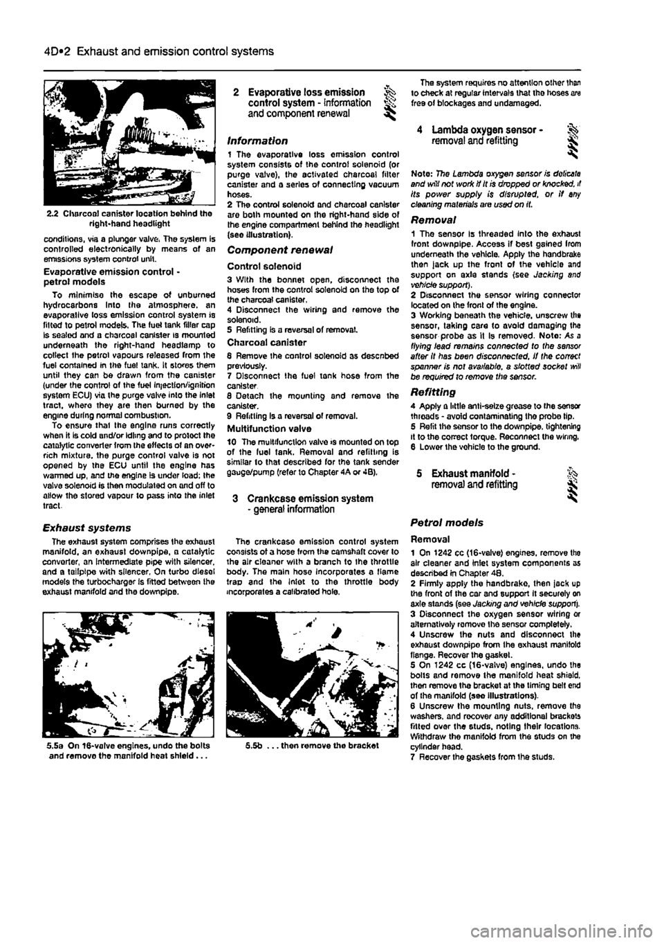
2.2 Charcoal canister location behind tho right-hand headlight
conditions, via a plunger valve, The system is controlled electronically by means of an emissions system control unit. Evaporative emission control • petrol models To minimise the escape of unburned hydrocarbons Into the atmosphere, an evaporallve loss emission control system is fitted to petrol models, The fuel tank filler cap Is sealed and a charcoal canister is mounted underneath the right-hand headlamp to collect the petrol vapours released from the fuel contained In the fuel tank. It stores them until they can be drawn from the canister (under the control of the fuel Injection/ignition system ECU) via the purge valve into the Inlet tract, where they are then burned by the engine during normal combustion. To ensure thai the engine runs correctly when it is cold and/or idling and to protect the catalytic converter from the effects of an over-rich mixture, the purge control valve is not opened by the ECU until the engine has warmed up, and the engine is under load; the valve solenoid is then modulated on and off to allow the stored vapour to pass into the inlet tract.
Exhaust systems The exhaust system comprises the exhaust manifold, an exhaust downpipe, • catalytic convorter, an intermediate pipe with silencer, and a tailpipe with silencer, On turbo diesel models the turbocharger is fitted between ihe exhaust manifold and the downpipe.
5.5a On 16-valve engines, undo the bolts and remove the manifold heat shield...
2 Evaporative loss emission ^ control system - information and component renewal ^
Information 1 The evaporative loss omission control system consists of the control solenoid (or purge valve), the activated charcoal filter canister and a series of connecting vacuum hoses. 2 The control solenoid and charcoal canister are both mounted on the right-hand side of the engine compartment behind the headlight (see illustration).
Component renewal
Control solenoid 3 With the bonnet open, disconnect the hoses from the control solenoid on the top of the charcoal canister. 4 Disconnect the wiring and remove the solenoid. 5 Refitting is a reversal of removal. Charcoal canister 6 Remove Ihe control solenoid as desenbed previously. 7 Disconnect Ihe fuel tonk hose from the canister 8 Detach the mounting and remove the canister. 9 Refitting Is a reversal of removal. Multifunction valve 10 The multifunction valve >s mounted on top of the luel tank. Removal and refitting is similar to that described for the tank sender gauge/pump (refer to Chapter 4A or 4B).
3 Crankcase emission system - general information
The crankcase emission control system consists of a hose from the camshaft cover to the air cloanor with a branch to Ihe throttle body. The main hose Incorporates a flame trap and the Inlet to the throttle body incorporates a calibrated hole.
5.5b ... then remove the bracket
The system requires no attention other than to check at regular intervals that tho hoses are free of blockages and undamaged.
4 Lambda oxygen sensor -removal and refitting &
Note: 7?5e Lambda oxygen sensor is doiicata and will not work if it is dropped or knocked, it its power supply is disrupted, or if any cleaning materials are used on it.
Removal 1 The sensor Is threaded Into the exhaust front downpipe. Access if best gained Irom underneath the vehicle. Apply the handbrake then )ack up the front of the vehicle and support on axle stands (see Jacking and vehicle support). 2 Disconnect the sensor wiring connector located on the front of the engine. 3 Working beneath the vehicle, unscrew the sensor, taking care to avoid damaging the sensor probe as it Is removed- Note: As a flying lead remains connected to the sensor after it has been disconnected, if the correct spanner is not available, a slotted socket
will
be required to remove the sensor.
Refitting A Apply a little anti-selze grease to (he sensor threads • avoid contaminating the probe tip. 5 Refit the sensor to the downpipe. tightening it to the correct torque. Reconnect the wiring. 6 Lower the vohicle to the ground.
5 Exhaust manifold - % removal and refitting jk
Petrol models
Removal 1 On 1242 cc (16-valve) engines, remove tho air cleaner and inlet system components as described in Chapter 48. 2 Firmly apply the handbrake, then jock up the front of the car and support It securely on axle stands (see Jacking and vehicle support). 3 Disconnect the oxygen sensor wiring or alternatively romovo Ihe sensor completely. 4 Unscrew the nuts and disconnect the exhaust downpipo from Ihe exhaust manifold flange. Recover the gasket. 5 On 1242 cc (16-valve) engines, undo the bolts and remove the manifold heat shield, then remove the bracket at the timing belt end of the manifold (seo Illustrations). 6 Unscrew the mounting nuts, remove the washers, and recover any additional brackets fitted over the studs, noting their locations. Withdraw the manifold from the studs on the cylinder head. 7 Recover the gaskets from Ihe studs.
Page 146 of 225
4D*3 Exhaust and emission control systems
Refitting 8 Refitting is a reversal of the removal pro-cedure but fit new gaskets. Tighten the nuts lo the specified torque.
Diesel models Note: On diesel models the inlet and exhaust
manifolds
are located on the rear of the engine
end
share the same securing nuts and gasket. Removal 8 Remove the inlet manifold as described In Part
C
of this Chapter. 10 Firmly apply the handbrake, then jack up lite front of tho car and support it securely on axle stands (see Jacking and vehicle support). 11 Straighten the tab washers (where fitted), then unscrew and remove the exhaust downpipe retaining nuts. Detach the downpipe from the manifold/turbocharger. Suitably support the downpipe. 12 Undo the manifold-to-cylinder head securing nuts and withdraw the manifold (see Illustration). 13 Separate the turbocharger from the manifold with reference to Chapter 4C. 14 Remove the gasket and clean the mating
(aces
of the manifold, cylinder head and down-pipe flange (see illustration). The gasket must
be
renewed when refitting the manifold, Refitting
15 Refitting is a reversal of the removal procedure but fit a new gasket. Tighten the retaining nuts to the specified torque and where necessary lock them by bending over
the
tocktabs.
6 Exhaust system - % general information and ^ component renewal
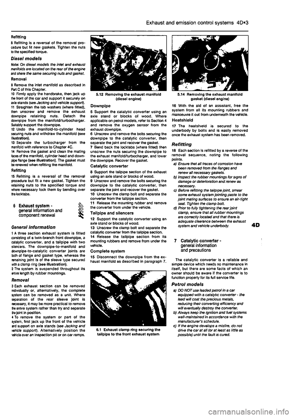
Genera/ Information 1 A three section exhaust system is fitted consisting of a twin-branch front downpipe, a catalytic converter, and a tailpipe with two silencers. The downpipe-to-manifold and downpipe-to-catalytic converter joints are both of flange and gasket type, whereas the remaining joint Is of the sleeve type secured
witn
a clamp ring (see illustration). 2 The system is suspended throughout its entire length by rubber mountings.
Removal 3 Each exhaust section can be removed individually or, alternatively, the complete system can be removed as a unit. Where separation of the rear sleeve Joint is necessary, it may be more practical to remove
the
entire system rather than try and separate
the Joint
In position. 4 To remove the system or part of the system, first jack up the front of the vehicle and support on axle stands (see Jacking and nhlcle support), Alternatively position the
vehicle
over an inspection pit or on car ramps.
5.12 Removing the exhaust manifold (diesel engine) Downpipe 5 Support the catalytic converter using an axle stand or blocks of wood. Where applicable on petrol models, refer to Section 4 and remove the oxygen sensor from the exhaust downpipe. 6 Unscrew and remove the bolts securing the downpipe to tha catalytic converter, then separate the joint and recover the gasket. 7 Bend back the locktabs (where fitted) then unscrew the nuts securing the downpipe to the exhaust manifold/turbocharger. and lower the downpipe, Recover the gasket. Catalytic converter
8 Support the tailpipe section of the exhaust using an axle stand or blocks of wood. 9 Unscrew and remove the bolts securing the downpipe to the catalytic converter, then separate the joint and recover the gasket. 10 Unscrew the clamp bolt and separate the converter from the tailpipe section. 11 Release the mounting rubber and remove the converter from under the vehicle. Tailpipe and silencers 12 Support the catalytic converter using an axle stand or blocks of wood. 13 Unscrew the clamp bolt and separate the catalytic converter from the tailpipe section. 14 Release the tailpipe section from its mounting rubbers and remove from under the vehicle. Complete system 15 Disconnect the downpipe from the ex-haust manifold as described in paragraph 7.
6.1 Exhaust clamp ring securing the tailpipe to the front exhaust system
5.14 Removing the oxhaust manifold gasket (diesel engine) 16 With the aid of an assistant, free the system from all its mounting rubbers and manoeuvre it out from underneath the vehicle. Heatshield 17 The heatshield is secured to the underbody by bolts and Is easily removed once the exhaust system has been removed.
Refitting 18 Each section is refitted by a reverse of the removal sequence, noting the following points. a) Ensure that all traces of corrosion have been removed from the flanges and renew ail necessary gaskets. b) Inspect the rubber mountings for signs of damage or deterioru tion and renew
as
necessary. c) Before refitting the tailpipe joint, smear some exhaust system jointing paste to the joint mating surfaces to ensure an air-tight seal. Tighten the clamp bolt. d) Prior to fully tightening the rear joint damp, ensure that all rubber mountings are correctly /ocafed and that there is adequate clearance between the exhaust system and vehicle underbody.
7 Catalytic converter -general information and precautions
The catalytic converter is a reliable and simple device which needs no maintenance In itself, but there are some facts of which an owner should be aware if the converter is to function properly for its full service life.
Petrol models a) DO NOT use leaded petrot In a car equipped with a catalytic converter - Ihe lead will coat the precious metals, redudng their converting efficiency
and
will eventually destroy the converter. b) Always keep the ignition and fuel systems well-maintained in accordance with the manufacturer's schedule. c) If the engine develops a misfire, do not drive the car at all (or at least as little
as
possible) until the fault is cured.
Page 154 of 225
5B*2 Ignition system - petrol models
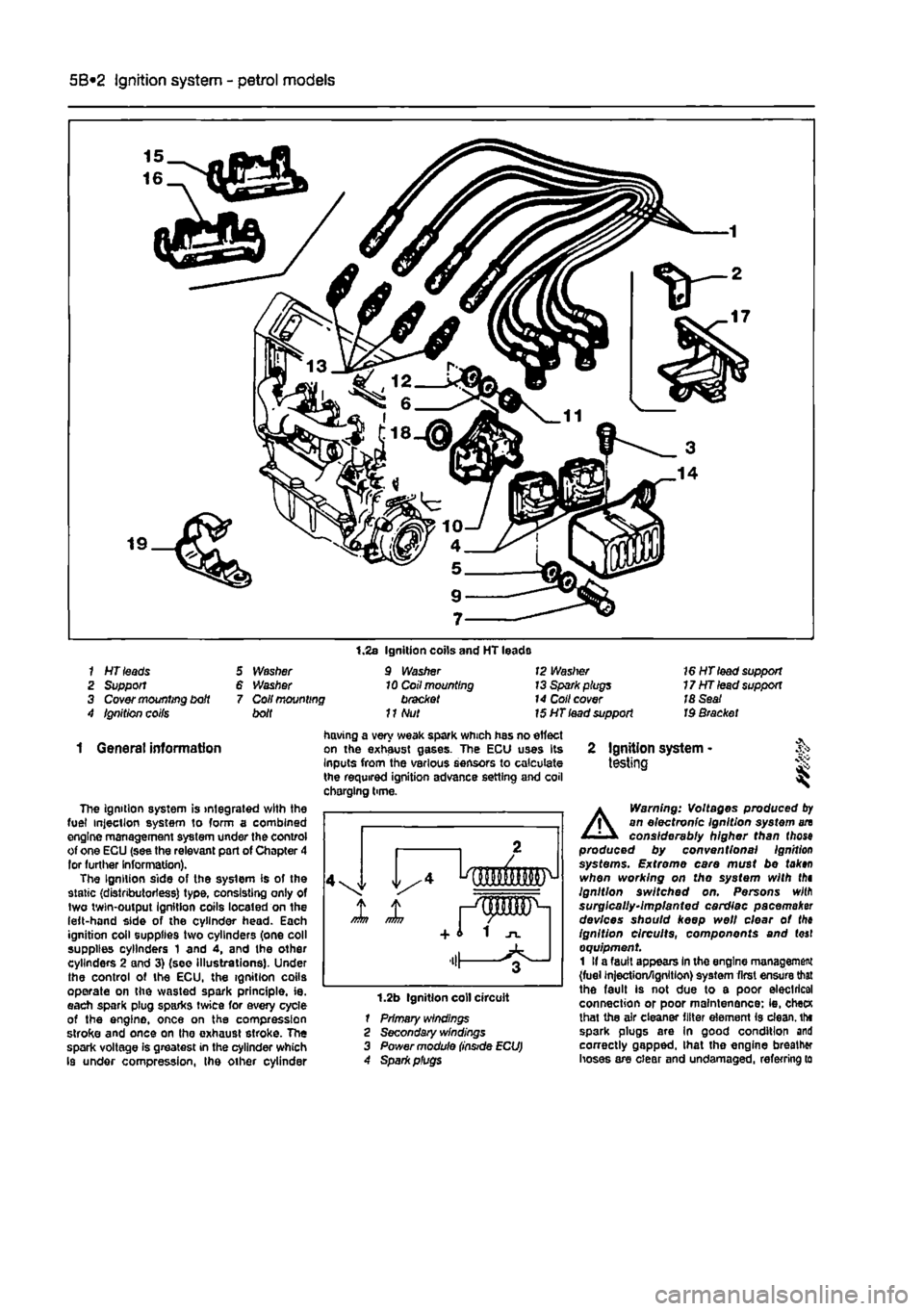
1 HT leads 2 Support 3 Cover mounting bdt 4 Ignition coifs
5 Washer 6 Washer 7 Coil mounting bolt
1.2s Ignition coils and HT leads 9 Washer 10 Coil mounting bracket
11
Nut
12 Waslrer 13 Spark plugs 14 Coll cover 15 HT lead support
16 HT lead support 17HTlead support 18 Seat Id Bracket
1 General information
The ignition system is integrated with the fuel injection system to form a combined engine management system under the control of one ECU (see the relevant part of Chapter 4 lor further Information). The Ignition side of the system is of the static (distributorless) type, consisting only of two twin-output Ignition coils located on the left-hand side of the cylinder head. Each ignition coil supplies two cylinders (one coll supplies cylinders 1 and 4, and the other cylinders 2 and 3) (see Illustrations). Under the control of the ECU, the ignition coils operate on the wasted spark principle, ie. each spark plug sparks twice for every cycle of the engine, once on the compression stroke and once on tho exhaust stroke. The spark voltage is greatest in the cylinder which Is under compression, the other cylinder
having a very weak spark which has no effect on the exhaust gases. The ECU uses Its Inputs from the various sensors to calculate the required ignition advance setting and coil chorging time.
1.2b Ignition coll circuit 1 Primary windings 2 Secondary windings 3 Power module
2 Ignition system -testing i
A
Warning: Voltages produced
by
an electronic Ignition system an considerably higher than (hose produced by conventional Ignition systems. Extreme care must be tak»n when working on tho system with thi Ignition switched on. Persons wilfl surgically-implanted cardiac pacemaker devices should keep well clear ot the ignition circuits, components and (oaf equipment 1 If a fault appears In the engine management (fuel injection/ignition) system first ensure that the fault is not due to a poor electrical connection or poor maintenance: ie, checK lhat the air cleaner filter element is clean, tht spark plugs are In good condition and correctly gapped, lhat the engine breather hoses are clear and undamaged, referring to
Page 164 of 225
Manual transmission 7A*3
3,8 Unscrew the nut and disconnect the gear selector rod from the lever on the transmission unscrew the locknut and adjusting nut from the end of the clutch cable and disconnect the cable from the transmission. Recover the damper block. On models with a hydraulically operated clutch, unscrew the mounting bolts, release the slave cylinder pushrod from the re&ase arm on the transmission, then position the cylinder to one side.
7 Unscrew and remove the reverse gear Inhibiting device from the transmission. Tie the cable to one side out of the way. 8 Unscrew the nut and disconnect the gear selector rod from the lever on the transmission (see illustration). 9 Pull out the clip then disconnect the gear engagement cable from the control lever and release the cable from the mounting bracket (see illustrations). 10 Unscrew and remove the two upper transmisslon-to-englne mounting bolts. Unscrew the single bolt securing the starter motor to the transmission. 11 Remove the air cleaner and air ducting with reference to Chapter 4A or 4B. This Is necessary In order to fit the engine hoist 12 On 5-speed transmissions, trace the wiring back from the electronic speedometer sensor and disconnect the connector located on the left-hand side of the engine (see illustration). 13 On 6-speed transmissions, unscrew the knurled nut and disconnect the speedometer cable from the top of the final drive housing. 14 Support the weight of the engine using a hoist attached to the engine lifting eyes, or alternatively use a trolley jack and block of wood beneath Ihe engine. 15 Unscrew the Lambda/oxygen sensor from the exhaust downpipe and position It In a safe place to prevent damage. 16 Unscrew the nuts securing the downpipe to the exhaust manifold, then lower It and support on an axle stand. Recover the gasket. 17 Unbolt the support bracket from the engine and transmission. Recover the spacer plate. 18 Unbolt and remove the transmission lower cover, 19 Unscrew the remaining starter motor mounting bolts and support tho starter motor to one side. 20 Loosen and remove the clips securing the left- and right-hand driveshaft gaiters to the transmission output shafts.
3.9a Remove the clip to release the gear engagement cable 21 Unscrew and remove the boils securing the left-hand swivel hub assembly to the front suspension strut, then separate the components and support the swivel hub on an axle stand. 22 Move the swivel hub assembly outwards and disconnect the inner end of the dnveshaft from the transmission output shaft. Support the shaft away from the transmission to prevent damage to the garters. 23 Working beneath the vehicle, unscrew the botts securing the rear engine mounting to the underbody then unscrew the bolts securing the mounting to the transmission and withdraw the mounting assembly from under the vehicle. 24 Unscrew the bolts securing the left-hand engine/transmission mounting to Ihe body then unscrew the bolts from the transmission and remove the mounting. 25 Support the woight of the transmission on a trolley jack then unscrew the remaining nut and bolt from the belihousing and pull the transmission away from the engine. Lower it and remove from under the vehicle. A Warning: Support the trans-mission to ensure that it remains steady on the jack head. Keep the transmission levet until the Input shaft Is fully withdrawn from the clutch friction plate. Refitting
26 Refitting is a reversal of the removal procedure, but note the following points. a) Apply a smear of high-melting-point grease to the clutch friction plate splines; take care to avoid contaminating the friction surfaces.
3.12 Electronic speedometer sensor fitted to 5-speed transmissions
3.9b Removing the gear engagement cable from the mounting bracket b) Tighten all bolts to Ihe specified torque. c) Fit new clips to secure the driveshaft gaiters to the transmission output shafts. d) Adjust the clutch cable (where applicable) as described In Chapter 6.
Diesel models
Removal 27 Seloct a solid, level surface to park the vehicle upon. Give yourself enough space to move around it easily. Apply the handbrake then jack up the front of tho vehicle and support on axlo stands (see Jacking and vehicle support). Remove both front wheels. 28 Unbolt the relay support then remove the batlery and mounting tray as described in Chapter 5A. 29 On models with a cable operated clutch, unscrew the locknut and adjusting nut from the end of the clutch cable and disconnect the cable from the transmission. Recover the damper block. On models with a hydraulically operated clutch, unscrew the mounting botts. release the slave cylinder pushrod from the release arm on the transmission, then position the cylinder to one side, 30 Unscrew the nut and disconnect the gear selector rod from the lever on the transmission. 31 Disconnect the gear engagement cable from the control lever then slide out the clip and release the cable from the mounting bracket. 32 Unbolt the electronic rev counter sensor from the upper rear of the belihousing and position it to one side (see illustration).
3.32 Electronic rev counter sensor located in the upper rear of the belihousing
Page 165 of 225
7A«4 Manual transmission
33 Remove lha air cleaner front section and air ducting with reference to Chapter 4C. Also disconnect the injection pump vacuum pipe from the clips on the left-hand end of the cylinder head. This work is necessary in order to fit the engine hoist 34 Support the weight of the engine using a hoist attached to the engine lifting eyes, or alternatively use a trolley Jack and block of wood beneath the engine. 35 Unscrew the nuts securing the downpipe to the exhaust manifold, then lower it and support on an axle stand. Recover the gasket. 36 Unscrew the starter motor mounting bolts and support the starter motor to one side. 37 Disconnect the wiring from the reversing light switch on the front of the transmission. 38 Unscrew the nut and disconnect the earth cable from its stud. 39 Trace the wiring back from the electronic speedometer sensor and disconnect the connector located on the left-hand side ot the engine. If a mechanical speedometer Is fitted unscrew the knurled collar and disconnect the cabte from the transmission. 40 Unbolt and remove the transmission lower cover. 41 Using an Allen key unscrew the bolts securing the inner end of the left-hand driveshaft to the transmission flange. Remove the bolts and recover the spacer plates. Support the driveshaft on an axle stand. 42 Unscrew and remove the bolts securing the left-hand swivel hub assembly to the front suspension strut, then separate the components and support the swivel hub on an axle stand. 43 Move the swrvel hub assembly outwards and support the driveshaft away from Ihe transmission. 44 Using an Allen key unscrew the bolts securing the Inner end of the right-hand driveshaft to the intermediate shaft flange. Remove the bolts and recover the spacer plates. Support the driveshaft on an axle stand. 45 Remove the intermediate driveshaft with reference to Chapter 8. 46 Working beneath the vehicle, unscrew the bolts securing the rear engine mounting to the underbody then unscrew the bolts securing the mounting to the transmission and withdraw the mounting assembly from under the vehicle.
47 Unscrew the bolts securing the left-hand engine/transmission mounting to the body then unscrew Ihe bolts from the transmission and remove the mounting. 48 Support the weight of the transmission on a trolley jack then unscrew the remaining nut and bolts from the bellhousing and pull the transmission away from the engine.
A
Warning: Support the trans-mission to ensure that It remains steady o/i the jack head. Keep the transmission level until the Input shaft
1$
fully withdrawn from the clutch friction plate.
Refitting 48 Refitting is a reversal of the removal procedure, but note the following points. a) Appiy a smear* of high-meiting-point grease to the clutch friction piate splines; take care to avoid contaminating the friction surfaces. b) Tighten all bolts to the specified torque. c) Fit new clips to secure the driveshaft gaiters to the transmission output shafts. d) Adjust the clutch cable (where applicable) as described In Chapter 6.
4 Manual transmission overhaul -general Infomtatlon
Overhauling a manual transmission is a difficult and Involved Job for the DIY home mechanic. In addition to dismantling and reassembling many small parts, clearances must be precisely measured and, if necessary, changed by selecting shims and spacers. Internal transmission components are also often difficult to obtain, and in many Instances, extremely expensive. Because of this, If the transmission develops a fault or becomes noisy. Ihe best course of action is to have the unit overhauled by a specialist repairer, or to obtain an exchange reconditioned unit. Nevertheless, it is not impossible for the more experienced mechanic to overhaul the transmission, provided the special tools are available, and the Job is done in a deliberate step-by-step manner, so that nothing is overlooked.
The tools necessary for an overhaul include internal and external clrclip pliers, bearing pullers, a slide hammer, a sat of pin punches, a dial test Indicator, and possibly a hydraulic press. In addition, a large, sturdy workbench 8od a vice will be required. During dismantling o1 the transmission, make careful notes of how each component
1$
fitted, to make reassembly easier and more accurate. Before dismantling the transmission, it will help if you have some idea what area is malfunctioning. Certain problems can be closely related to specific areas In the transmission, which can make component examination and replacement easier. Refer to the Fault Finding Section at the end of this manual for more Information.
5 Reversing light switch -testing, removal and refitting ||
Testing 1 The reversing light circuit is controlled by a plunger-type switch screwed into the front of the transmission casing. If a fault develops, first ensure that Ihe circuit fuse has not blown. 2 To test the switch, disconnect the wiring connector, and use a multimeter (set to the resistance function) or a battery-and-bulb test circuit to check that there is continuity between the switch terminals only when reverse gear is selected. If this is not the case, and there are no obvious breaks or other damage to the wires, the switch is faulty, and must be renewed.
Removal 3 Access to the reversing light switch Is best achieved from under the vehicle. Apply the handbrake then jack up Ihe front of the vehicle and support on axle stands (see Jacking and vehicle support). 4 Disconnect the wiring connector, then unscrew It from the transmission casing.
Refitting 5 Refit the switch and tighten securely. 6 Reconnect the wiring then lower the vehicle to the ground.
Page 169 of 225
7B*4 Automatic transmission
2 Automatic transmission - ^ removal and refitting St
Removal 1 Select a solid, level surface to park the vehicle upon. Give yourself enough space to move around it easily. Apply the handbrake then jack up the front of the vehicle and support on axle stands (see Jacking and vehicle support). Remove both front wheels, 2 Remove the battery and mounting tray as described In Chapter 5A. 3 Remove the air cleaner and air inlet duct as described In Chapter 4A. 4 Disconnect the kickdown cable at the sector on the throttle housing and detach It from the mounting on the camshaft cover. Also release the cable from the support on the left-hand end of the cylinder head. 5 Disconnect the wiring connectors on the transmission. 6 Disconnect the fluid inlet and outlet Unas from the heat exchanger on top of the transmission. 7 Pull the fluid level dipstick from Its tube on the front of the transmission and tape over the top of the tube to prevent dirt entry. 8 Unscrew and remove the retaining pin and disconnect the speed selector cable from the top of the transmission. 9 Unscrew the upper bolt securing the starter motor to the transmission. 10 Unscrew the upper bolts securing the transmission to the engine. 11 Support the weight of the engine using a hoist attached to the engine lifting eyes, or alternatively UBO a trolley jack and block of wood beneath the engine, 12 Remove the screws and remove the front wheel arch liner from under the left-hand wheel arch. 13 Unscrew the nut securing the earth cablo to the transmission. 14 Using a punch drive out the roll pins securing both driveshafts to the final drive output shafts. 15 Unscrew and remove the bolts securing the left-hand swivel hub assembly to the front suspension strut, then separate the components and support the swivel hub on an axle stand. 16 Move the swivel hub assembly outwards and slide the inner end of the driveshaft from the splines on the transmission output shaft. Support the shaft away from the transmission to prevent damage to the gaiters. 17 Unscrew the lambdafoxygen sensor from the exhaust downpipe and position it In a safe place to prevent damage. 18 Unscrew ihe nuts securing the downpipe to Ihe exhaust manifold, then lower It and suppon on an axle stand. Recover the gasket. 19 Unscrew the knurled nut and disconnect the speedometer cable from the top of the final drive housing.
3-2 Locking the flywheel when removing the electromagnetic clutch 20 Unscrew the remaining bolt securing the staner motor to the transmission 21 Unbolt and remove Ihe lower flywheel cover from the transmission. 22 Working beneath the vehicle, unscrew the bolts securing the rear engine mounting to the underbody then unscrew the bolts securing the mounting lo the transmission and withdraw the mounting assembly from under the vehicle. 23 Unscrew the bolts securing the left-hand engine/transmission mounting to the body thon unscrew the bolts from the transmission and remove the mounting. 24 Support the weight of the transmission on a trolley jack then unscrew the remaining nut and bolt from the bellhouslng and pull the transmission away from the engine. Lower it and remove from under the vehicle.
A
Warning: Support the transmission to ensure that It remains steady on the Jack head. Keep the transmission level until the Input shaft and pump shaft are fully withdrawn from the electromagnetic clutch housing.
Refitting 25 Refitting is a reversal of the removal procedure, but note the following points. a} Apply a smear of high-melting-point grease to the splines of the transmission input shaft and oil pump driveshaft.
3.6 Checking the resistance of the clutch windings 1 Slip rings
0) Tighten all nuts and bolts to the
specified
torque, where given, c) Renew both driveshaft roll pins.
3 Electro-magnetic clutch • & removal, inspection 5. and refitting ^
Removal 1 Remove Ihe transmission as described n Section 2. 2 Turn the flywheel so that two of the lour mounting bolts are accessible, Hold tha flywheel stationary then unscrew Ihe tvrt bolts. To hold the flywheel, Insert a wida bladed screwdriver In the ring gear teeth or alternatively use a piece of angle iron against one of the retaining bolts temporarily Inserted in the cylinder block (see illustration). 3 Turn the crankshaft half a turn and unscrew the remaining bolts, then withdraw the electromagnetic clutch.
Inspection 4 Turn the driven element by means of tha slip rings, and check that the bearing is not noisy or rough. 5 Inspect the slip rings for burning or other damage. Clean them if necessary using fid and a clean rag. 6 Check the resistance of the clutch windings, using an ohmmetor connected across the slip rings (see Illustration). The resistance at 20*0 should be 2 to 4 ohms. 7 Check the Insulation of the windings, using an ohmmeter connected between either sip ring and the body of the clutch (see illustration). Resistance should be Infinity. 8 If the clutch fails any of the foregoing checks, renew it. Apart from the brush gear, Individual spares are not available.
Refitting 9 Refitting is a reversal of removal but tighten all bolts to the specified torque.
windings
Page 171 of 225
7B*6 Automatic transmission
Gear selector cable -adjustment
1 Remove the battery and tray as described In Chapter 5A for access to the transmission. 2 Disconnect the selector cable from the lever on Ihe transmission. 3 Move the selector fever inside the vehicle to the N (Neutral) position, then move the lever on the transmission to Its central (Neutral) position. Locate the cable end over the lever. If the cable end fitting does not line up exactly with the hole In Ihe lever, loosen the adjustment nut and reposition the end fitting. 4 With the adjustment correct reconnect tha cable to the lever, then move the selector lever to the P (Park) position. Check that the lever on the transmission has also moved to the P position. 6 Refit the battery and tray as described in Chapter 5A. 6 Road test the vehicle, and check for correct operation in all selector lever positions.
9 Gear selector cable -removal and refitting at
7 Inside the vehicle disconnect the selector cable from the bottom of the selector lever (hen remove it from the support bracket, a Withdraw the cable into the engine compartment, and remove it.
Refitting 9 Refitting is a reversal of removal, but adjust the cable as described in Section 8. 10 Check that It is only possible to start the engine in positions P and N. Reposition the selector lever switch If necessary. 11 Road test the vehicle, and check for correct operation In ell selector lever positions.
10 Transmission oil pump - & mnvtiifll rAtiMlitA removal a/id refitting
Removal 1 Using an Allen key. unscrew the screw and remove the selector lever knob from the lever. 2 Remove the oddment tray and the ashtray. 3 Remove the screws and withdraw the centre console and selector mechanism cover. 4 Unscrew the mounting screws, slightly lift the centre console, then disconnect the wiring and remove the console, 5 Remove the battery and tray as described in Chapter 5A for access to the transmission, 6 Disconnect the selector cable from the lever on the transmission.
Removal 1 Apply the handbrake, then lack up the front of the vehicle and support on axle stands (see Jacking and vehicle support). Remove the left-hand wheel. 2 Unscrew the screws and remove the wheel arch liner. 3 Working through the left-hand wheel arch, remove Ihe three bolts which secure the oil pump. 4 Attach a slide hammer to the oil pump, using the two tapped holes provided. Withdraw the pump using the slide hammer. Be prepared for some oil spillage. Recover the gasket end O-ring (see illustrations). 5 If the pump is defective, it must be renewed; no spares are available.
Refitting 6 Before refitting Ihe oil pump, clean Ihe mating surfaces of the transmission and pump. 7 Rt the oil pump, U9ing a new gasket and a new O-ring. Secure the pump with the three bolts.
8 Refit the wheel arch liner, then refit tto wheel and lower the vehicle to the ground. 9 Check the transmission fluid level » described earlier in this Section, and top-upif necessary.
11 Accelerator pedal & mfcro-Bwftcb(es) -checking
and
adjustment ^
1 Correct adjustment of the micro-awtlch which senses the accelerator pedal position s essential for correct operation of the clutch.
A
quick check can be made by listening for the switch clicking as the accelerator a depressed. For an accurate check, proceed as follows. 2 Disconnect Ihe mlcroswitch wiring connector (nside the vehicle. Connect a continuity tester across the terminals of the switch, located at the top of (he pedal box (see Illustration}. 3 Remove the air cleaner and air ducting as described in Chapter 4A. 4 With the accelerator pedal releassd, th« switch must be closed (zero resistance). Slowty depress the pedal, and check that the switch opens when the throttle valve on the throttle housing is 30° open. This will occur when the pedal has travelled between 3 and 7 mm. Adjust the switch position if necessary. 5 If the switch is permanently open or permanently closed, and adjustment makes no difference, renew ft. 6 Remake the original wiring connections on completion,
12 Automatic transmission -overhaul
Apart from the operations described earlier in this Section, transmission overhaul should be entrusted to a Rat dealer or transmission specialist.
10.4a Using a slide hammer to remove the oil pump from the transmission 10.4b Automatic transmission oil pump O-dng (1), housing (2) and gasket (3) 11.2 Continuity tester connected ecross the accelerator pedal micro-switch
Page 203 of 225
11 *2 Bodywork and fittings
on vehicles with wax-based underbody protective coating, or the coating will be removed. Such vehicles should be inspected annually, preferably just prior lo Winter, when the underbody should be washed down, and any damage to the wax coating repaired. Ideally, a completely fresh coat should be applied. It would also be worth considering the use of such wax-based protection for injection into door panels, sills, box sections, etc, as an additional safeguard against rust damage, where such protection Is not provided by the vehicle manufacturer. After washing paintwork, wipe off with a chamois feather to give an unspotted clear finish. A coat of clear protective wax polish wilt give added protection against chemical pollutants in the air. If the paintwork sheen has duiled or oxidised, use a cleaner/polisher combination to restore the brilliance of the shine. This requires a little effort, but such dulling Is usually caused because regular washing has been neglected. Care needs to be taken with metallic paintwork, as special non-abrasive cleaner/polisher is required to avoid damage to the finish, Always check that the door and ventilator opening drain holes and pipes are completely clear, so that water can be drained out. Brightwork should be treated In the same way as paintwork. Windscreens and windows can be kept clear of the smeary film which often appears, by the use of proprietary glass cleaner. Nover use any form of wax or other body or chromium polish on glass.
Maintenance -upholstery and carpets
Mats and carpets should be brushed or vacuum-cleaned regularly, to keep them free of grit. If they are badly stained, remove them from the vehicle for scrubbing or sponging, and make quite sure they are dry before refitting. Seats and interior trim panels can be kept clean by wiping with a damp cloth. If they do become stained (which can be more apparent on light-coloured upholstery), use a little liquid detergent and a soft nail brush lo scour the grime out of the grain of the material. Do not forget to keep the headlining clean in the same way as the upholstery. When using liquid cleaners inside the vehicle, do not over-wet the surfaces being cleaned. Excessive damp could get Into the seams and padded interior, causing stains, offensive odours or even rot.
If the Inside of the vehicle gets wet accidentally, tt Is worthwhile taking some trouble to dry ft out property, particularly where carpets an involved. Do not leave oil or electric heaters inside the vehicle for this purpose.
4 Minor body damage -repair
Repairs of minor scratches In bodywork If the scratch Is very superficial, and does not penetrate to the metal of the bodywork, repair is very simple. Lightly rub the area of the scratch with a paintwork renovator, or a very fine cutting paste, to remove loose paint from the scratch, and to clear the surrounding bodywork of wax polish, Rinse the area with clean water. Apply touch-up paint to ihe scratch using a fine paint brush; continue to apply fine layers of paint until the surface of the paint In the scratch Is level with the surrounding paintwork. Allow Ihe new paint at least two weeks to harden, then blend it Into the surrounding paintwork by rubbing the scratch area with a paintwork renovator or a very fine cutting paste. Finally, apply wax polish. Where the scratch has penetrated right through to the metal of the bodywork, causing the metal to rust, a different repair technique Is required. Remove any loose rust from the bottom of the scratch with a penknife, then apply rust-inhibiting paint to prevent the formation of rust in the future. Using a rubber or nylon applicator, fill the scratch with bodystopper paste. If required, this paste can be mixed with cellulose thinners to provide a very thin paste which is ideal for filling narrow scratches. Before the stopper-paste in Ihe scratch hardens, wrap a piece of smooth cotton rag around the top of a finger. Dip the finger in cellulose thinners, and quickly sweep it across the surface of the stopper-paste in the scratch: this will ensure that the surface of the stopper-paste is slightly hollowed. The scratch can now be painted over as described earlier In this Section.
Repairs of dents in bodywork When deop denting of the vehicle's bodywork has taken place, the first task is to put) the dent out. until the affected bodywork almost attains rts onginal shape. There is little polnl in trying to restore Ihe original shape completely, as the metal in the damaged area will have stretched on impact, and cannot be reshaped fully to its original contour. It Is better to bring the level of the dent up to a point which is about 3 mm below the level of the surrounding bodywork. In cases where Ihe dent is very shallow anyway, It is not worth trying to pull it out at all. If the underside of the dent is accessible, it can be hammered out gently from behind, using a mallet with a wooden or plastic head, Whilst doing this, hold a suitable block of wood firmly against (he outside of Ihe panel, to absorb the impact from the hammer blows and thus prevent a large area of the bodywork from being 'belled-out".
Should the dent be In a section of (I* bodywork which has a double skin, or seme other factor making It Inaccessible from behind, a different technique is called for. Dull several small holes through the metal inside Ihe area - particularly in the deeper section. Then screw long self-tapping screws Into the holes, just sufficiently for them to gain a good purchase in the metal. Now the dent can be pulled out by pulling on the protruding heads of the screws with a pair of pliers. The next stage of the repair Is the removal of the paint from the damaged area, and from an inch or so of the surrounding 'sound' bodywork. This is accomplished most easily by using a wire brush or abrasive pad on a posver drill, although it can be done just as effectively by hand, using sheets of abrasive paper. To complete the preparation for filling, score the surface of the bare metal wflhi screwdriver or the tang of 8 file, or alternatively, drill small holes In the affected area. This will provide a really good 'key' for the filler paste. To complete the repair, see the Section on filling and respraying.
Repairs of rust holes or gashes in bodywork Remove all paint from the affected area, and from an inch or so of the surrounding 'sound' bodywork, using an abrasive pad
or a
wire brush on a power drill. If these are not available, a few sheets of abrasive paper wil do the job most effectively. With the paint removed, you will be able to judge the severity of the corrosion, and therefore decide whether to renew the whole panel (if this is possible) or to repair the affected area. New body panels are not as expansive as most people think, and it is often quicker and more satisfactory to fit a new panel than to attempt to repair large areas of corrosion. Remove all fittings from Ihe affected area, except those which will act as a guide to ttie original shape of the damaged bodywork (eg headlight shells etc). Then, using tin snips
or a
hacksaw blade, remove all loose metal snd any other metal badly affected by corrosion. Hammer the edges of the hole inwards, in order to create a slight depression for the filer paste. Wire-brush the affected area to remove tha powdery rust from the surface of the remaining metal. Paint Ihe affected area with rust-inhibiting paint, if the beck of the rusted area is accessible, treat this also. Before filling can take place, ft will be necessary to block the hole in some
way.
TNs can be achieved by the use of aluminium cr plastic mesh, or aluminium tape. Aluminium or plastic mesh, or glass-fibre matting, is probably the best material to use for a large hole. Cut a piece to tha approximate size and shape of tho hole to b« filled, then position it In the hole so that its edges are below the level of the surrounding bodywork. It can be retained in position by
Page 204 of 225
Bodywork and fittings
11
*3
several blobs of filler paste around its periphery. Aluminium tape should be used for small or very narrow holes. Pull a piece off the roll, trim it to the approximate size and shape required, then pull off the backing paper (if used) and stick the tape over the hole; it can be overlapped if the thickness of one piece is Insufficient. Burnish down the edges of the tape with the handle of a screwdriver or similar, to ensure that the tape is securely attached to the metal underneath.
Bodywork repairs -filling and respraying Before using this Section, see the Sections on dent, deep scratch, rust holes and gash repairs. Many types of bodyfiller are available, but generally speaking, those proprietary kits which contain a tin of filler paste and a tube of resin hardener are best for this type of repair. A wide, flexible plastic or nylon applicator will be found invaluable for imparting a smooth and well-contoured finish to the surface of the filler. Mix up a little filler on a clean piece of card or board • measure the hardener carefully (follow the maker's instructions on the pack), otherwise the filler will set too rapidly or too slowly. U3ing the applicator, apply the filler paste to the prepared area; draw the applicator across the surface of the filler to achieve the correct contour and to level the surface. As soon as a contour that approximates to the correct one is achieved, stop working the paste - if you carry on too long, the paste will become sticky and begin lo 'pick-up' on the applicator. Continue to add thin layers of filler paste at 20-minute Intervals, until the level of the filler is just proud of the surrounding bodywork. Once the filler has hardened, the excess can be removed using a metal plane or file. From then on, progressively-finer grades of abrasive paper should be used, starting with a 40-grade production paper, and finishing with a 400-grade wet-and-dry paper. Always wrap the abrasive paper around a flat rubber, cork, or wooden block • otherwise the surface of the filler will not be completely flat. During the smoothing of the filler surface, the wet-and-dry paper should be periodically rinsed in water. This will ensure that a very smooth finish is imparled to the filler at the final stage. At this stage, the dent should be surrounded by a ring of bare metal, which in turn should be encircled by the finely feathered' edge of the good paintwork. Rinse the repair area with clean water, until all of the dust produced by the rubbing-down operation has gone. Spray the whole area with a light coat of primer - this will show up any imperfections In the surface of the filler. Repair these imperfections with fresh filler paste or bodystopper, and once more smooth the surface with abrasive paper. Repeat this
spray-and-repair procedure until you are satisfied that the surface of the filler, and the feathered edge of the paintwork, are perfect. Clean the repair area with clean water, and allow to dry fully.
flflfl^gl tf txxfystopper is used, it can WiMiiBi be mixed with cellulose Hi NT thinners to form a really thin 1 1 paste which is Ideal for filling small holes.
The repair area Is now ready for final spraying. Paint spraying must be carried out in a warm, dry, windless and dust-free atmosphere. This condition can be created artificially if you have access to a large indoor working area, but If you are forced to work in the open, you will have to pick your day very carefully. If you are working indoors, dousing the floor In the work area with water will help to settle the dust which would otherwise be in the atmosphere. If the repair area is confined to one body panel, mask off the surrounding panels; this will help to minimise the effects of a slight mis-match in paint colours. Bodywork fittings (eg chrome strips, door handles etc) will also need to be masked off. Use genuine masking tape, and several thicknesses of newspaper, for the masking operations. Before commencing to spray, agitate the aerosol can thoroughly, then spray a test area (an old tin. or similar) until the technique is mastered. Cover the repair area with a thick coat of primer; the thickness should be built up using several thin layers of paint, rather than one thick one. Using 400-grade wet-and-dry paper, rub down the surface of the pnmer until it is really smooth. While doing this, the work area should be thoroughly doused with water, and the wet-and-dry paper periodically rinsed in water. Allow to dry before spraying on more paint. Spray on the top coat, again building up the thickness by using several thin layers of paint. Start spraying at one edge of the repair area, and then, using a side-to-side motion, work until the whole repair area and about 2 inches of the surrounding original paintwork is covered. Remove all masking material 10 to 15 minutes after spraying on the final coat of paint. Allow the new paint at least two weeks to harden, then, using a paintwork renovator, or a very fine cutting paste, blend the edges of the paint into the existing paintwork. Finally, apply wax polish.
Plastic components With the use of more and more plastic body components by the vehicle manufacturers (eg bumpers, spoilers, and in some cases major body panels), rectification of more serious damage to such items has become a matter of either entrusting repair work to a specialist in this field, or renewing complete components. Repair of such damage by the
DIY owner is not really feasible, owing to the cost of the equipment and materials required for effecting such repairs. The basic technique involves making a groove along the line of the crack in the plastic, using a rotary burr In a power drill. The damaged part is then welded back together, using a hot-air gun to heat up and fuse a plastic filler rod Into the groove. Any excess plastic is then removed, and the area rubbed down to a smooth finish. It is important that a filler rod of the correct plastic is used, as body components can be made of a variety of different types (eg polycarbonate, ABS, polypropylene). Damage of a less senous nature (abrasions, minor cracks etc) can be repaired by the DIY owner using a two-part epoxy filler repair material. Once mixed in equal proportions, this is used in similar fashion to the bodywork filler used on metal panels. The filler is usually cured in twenty to thirty minutes, ready for sanding and painting. If the owner is renewing a complete component himself, or If he has repaired it with epoxy filler, he will be left with the problem of finding a suitable paint for finishing which is compatible with the type of plastic used. At one time, the use of a universal paint was not possible, owing to the complex range of plastics encountered In body component applications. Standard paints, generally speaking, will not bond to plastic or rubber satisfactorily. However, it is now possible to obtain a plastic body parts finishing kit which consists of a pre-pnmer treatment, a primer and coloured top coat. Full Instructions are normally supplied with a kit, but basically, the method of use is to first apply the pre-pnmer to the component concerned, and allow It to dry for up to 30 minutes. Then the primer is applied, and left to dry for about an hour before finally applying the special-coloured top coat. The result is a correctly-coloured component, where the paint will flex with the plastic or rubber, a property that standard paint does not normally possess.
5 Major body damage -repair
Where serious damage has occurred, or large areas need renewal due to neglect, it means that complete new panels will need welding-in, and this is best left to professionals. If the damage is due to Impact, it will also be necessary to check completely the alignment of the bodyshell, and this can only be carried out accurately by a Fiat dealer using special jigs. If the alignment of the bodyshell is not corrected, the car's handling may be seriously affected. In addition, excessive stress may be Imposed on the steering, suspension, tyres or transmission, causing abnormal wear or even complete failure.