check transmission fluid FIAT PUNTO 1999 176 / 1.G User Guide
[x] Cancel search | Manufacturer: FIAT, Model Year: 1999, Model line: PUNTO, Model: FIAT PUNTO 1999 176 / 1.GPages: 225, PDF Size: 18.54 MB
Page 39 of 225
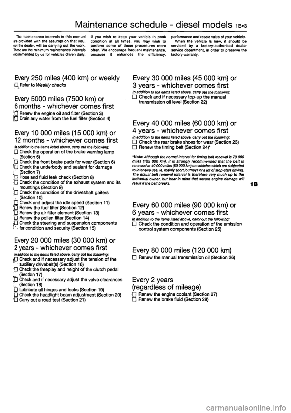
Maintenance schedule - diesel models 1B.3
The mamtenance intervals in this manual are provided with the assumption that you. reI ihe dealer, will be carrying out the work.
These
are the minimum maintenance intervals recommended by us for vehicles driven daily.
ff you wish to keep your vehicle In peak condition at all times, you may wish to perform some of these procedures more often. We encourage frequent maintenance, because it enhances the efficiency.
performance and resale value of your vehicle. When the vehicle Is new, it should be serviced by a factory-authorised dealer service department, in order to preserve the factory warranty.
Every 250 miles (400 km) or weekly O Refer to Weekly checks
Every 5000 miles (7500 km) or
6
months - whichever comes first • Renew the engine oil and filter (Section 3) P Drain any water from the fuel filter (Section 4)
Every 10 000 miles (15 000 km) or
12
months - whichever comes first ill addition lo tho Items listed above, cany out the following; D Check the operation of the brake warning lamp J (Section 5) Check the front brake pads for wear (Section 6) :-G Check the underbody and sealant for damage j" (Section 7) n Hose and fluid leak check (Section 8) 0 Check the condition of the exhaust system and its 1 mountings (Section 9) -D Check the condition of the driveshaft gaiters ", (Section 10) O Check and adjust the idle speed (Section 11) ;0 Renew (he fuel filter (Section 12) J] Renew the air filter element (Section 13) L) Renew the pollen filter (Section 14) •• Check the steering and suspension components • for condition and security (Section 15)
Every 20 000 miles (30 000 km) or
2
years - whichever comes first In addition to the Items listed above, cany out the following: (P Check and if necessary adjust the tension of the auxiliary drlvebeltfs) (Section 16) '• Check the freeplay and height of the clutch pedal " (Section 17) D Check and if necessary adjust the valve clearances (Section 18) Lubricate all hinges and locks (Section 19) • Check the headlight beam adjustment (Section 20) O Cany out a road test (Section 21)
Every 30 000 miles (45 000 km) or
3 years - whichever comes first In addition to the Items listed above, cany out the following: • Check and if necessary top-up the manual transmission oil level (Section 22)
Every 40 000 miles (60 000 km) or
4 years - whichever comes first In addition to the items listed above, cany out the following: • Check the rear brake shoes for wear (Section 23) • Renew the timing belt (Section 24)'
•Note: Although the normal interval for timing belt renewal is 70 000 miles (ids 000 km), it is strongly recommended that the belt Is renewed at 40 000 miles (60 000 km) on vehicles which are subjected to intensive use, le. mainly short Journeys or a lot of stop-start driving. The actual bait renewal interval Is therefore very much up to the Individual owner, but bear in mind that sevefe engine damage will result if the belt breaks.
Every 60 000 miles (90 000 km) or
6 years - whichever comes first In addition to the Items listed above, cany out the following: • Check the condition and operation of the emission control system components (Section 25)
Every 80 000 miles (120 000 km) • Renew the manual transmission oil (Section 26)
Every 2 years
(regardless of mileage) • Renew the engine coolant (Section 27) • Renew the brake fluid (Section 28)
Page 48 of 225
1B«12 Every 20 000 miles - diesel models
21 Road test
Instruments and electrical equipment 1 Check the operation of atl instruments and electrical equipment. 2 Make sure that all instruments read correctly, and switch on all electrical equipment rn turn, to check that It functions properly. Steering and suspension 3 Check for any abnormalities in the steering, suspension, handling or road feel. 4 Drive the vehicle, and check that there are no unusual vibrations or noises. 5 Check that the steering feete positive, with no excessive sloppiness, or roughness, and check for any suspension noises when cornering and driving over bumps. Drivetrain 6 Check (he performance of the engine, clutch, transmission and driveshafts.
7 Listen for any unusual noises from the engine, clutch and transmission. 8 Make sure that the engine runs smoothly when Idling, and that there is no hesitation when accelerating. 9 Check that the clutch action is smooth and progressive, that tho drive is taken up smoothly, and that the pedal travel Is not excessive. Also listen for any noises when the clutch pedal is depressed. 10 Check that all gears can be engaged smoothly without noise, and that the gear lever action Is not abnormally vague or notchy. 11 Listen for a metallic clicking sound from ihe front of the vehicle, as the vehicle « driven slowly In a circle with the steering on full-lock. Carry out this check In both directions, if a clicking noise is heard, this Indicates wear in a driveshaft |oinl, in which case renew the joint if necessary.
Check the braking system 12 Make sure that the vehicle does not pull to one side when braking, and that the wheels do not lock prematurely when braking hard.
13 Check that there Is no vibration through the steering when braking. 14 Check that the handbrake operates correctiy without excessive movement of th« lever, end that it holds the vehicle stationery on a slope. 15 Test the operation of the brake servo unit as follows. With the engine off, depress the footbrake four or five times to exhaust the vacuum. Hold the brake pedal depressed, then start the engine. As the engine starts, there should be a noticeable give In the brake pedal as vacuum builds up. Allow the engine to run for at least two minutes, and then switch it off. If the brake pedal is depressed now, it should be possible to detect a hiss from the servo es the pedal is depressed. After about four or five applications, no fimher hissing should be heard, and the pedal should feel considerably harder. Note: The vacuum for the servo unit is provided by the vacuum pump mounted on the left-hand end of t/ie cylinder head.
Every 30 000 miles (45 000 km) or 3 years
22 Manual transmission oil level check ;5§
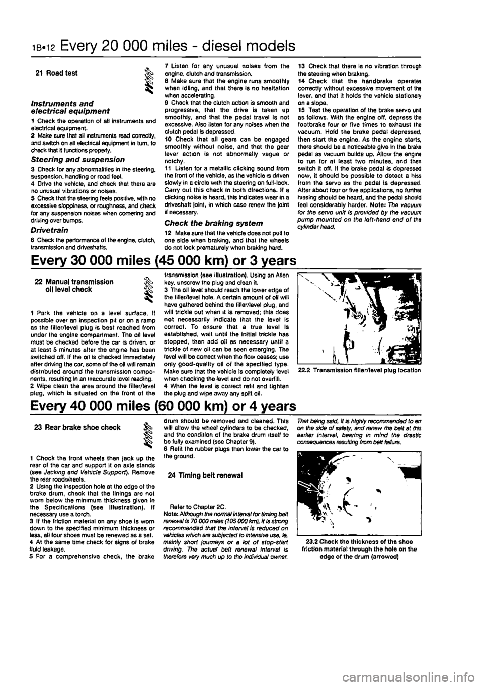
1 Park the vehicle on a level surface. If possible over an inspection pit or on a ramp as the filler/level plug is best reached from under Ihe engine compartment. The oil level must be checked before the car Is driven, or at least 5 minutes after the engine has been switched off. If the oil is checked Immediately after driving the car. some of the oil will remain distnbuted around the transmission compo-nents, resulting In an inaccurate level reading. 2 Wipe clean the area around the filler/level plug, which is situated on tho front of the
transmission (see illustration). Using an Allen key. unscrew the plug and clean it. 3 The oil level should reach the lower edge of the filler/level hole. A certain amount of oil will have gathered behind the filler/level plug, and will trickle out when it is removed; this does not necessarily Indicate that the level Is correct. To ensure that a true level Is established, wait until the Initial trickle has stopped, then add oil as necessary until a trickle of new oil can be seen emerging. The level will be correct when the flow ceases; use only good-quality oil of the specified type-Make sure that the vehicle Is completely level when checking the level and do not overfill. 4 When the level is correct refit and tighten the plug and wipe away any spilt oil.
22.2 Transmission filler/level plug location
Every 40 000 miles (60 000 km) or 4 years
23 Rear brake shoe check
1 Chock the front wheels then jack up the rear of the car and support It on axle stands (see Jacking and Vehicle Support), Remove the rear roadwhecla. 2 Using the inspection hole at the edge ot the brake drum, check that the linings are not worn below the minimum thickness given In the Spec ifi cat Ions (see Illustration). If necessary use a torch. 3 If the friction material on any shoe is worn down to the specified minimum thickness or iess. all four shoes must be renewed as a set, 4 At the same time check for signs of brake fluid leakage. 5 For a comprehensive check, the brake
drum should be removed and cleaned. This will allow the wheel cylinders to be checked, and the condition of the brake drum itself to be fully examined (see Chapter 9). 8 Refit the rubber plugs then lower the car to the ground.
24 Timing belt renewal
Refer to Chapter 2C. Note: Although the normal interval for timing belt
ranees/a!
is 70 000
mHes
(105 000
km),
it is strong recommended that the interval is reduced on vehicles which are subjected to intensive use, ie, mainly short journeys or a lot of stop-start driving. The actual belt renewal interval is therefore very much up to tho individual owner.
That being said, it is highly recommended to err on the side of safety, and renew (he belt at
this
earlier interval, bearing in mind the drastic consequences resulting from belt fetfure.
23.2 Check the thickness of the shoe friction material through the hole on the edge of the drum (arrowed)
Page 155 of 225
Ignition system - petrol models 5B®3
Chapter 1A tor further information. Also check tnat tha accelerator cable is correctly adjusted
as
described in the relevant part of Chapter 4. If the engine is running very roughly, check the compression pressures and the valve clearances as descnbed In the relevant parts of Chapters 1 and 2. 2
H
these checks fall to reveal the cause of the problem, the vehicle should be taken to a suitably equipped Fiat dealer for testing. A wiring block connector Is Incorporated in the engine management circuit Into which a special electronic diagnostic tester can be plugged. The tester will locate the fault quickly and simply alleviating the need to test all the system components Individually which is a time consuming operation that carries a high risk of damaging the ECU. 3 The only Ignition system checks which can
oe
earned out by the home mechanic are those cescribed in Chapter 1A, relating to the spark plugs, and the ignition coll test descnbed In this Chapter. If necessary, the system wiring and wiring connectors can oe checked as descnbed in Chapter 12, Section 2, ensuring that the ECU wiring connector(s) have first
been
disconnected.
3 Ignition HT coil - ^ removal, testing and refitting
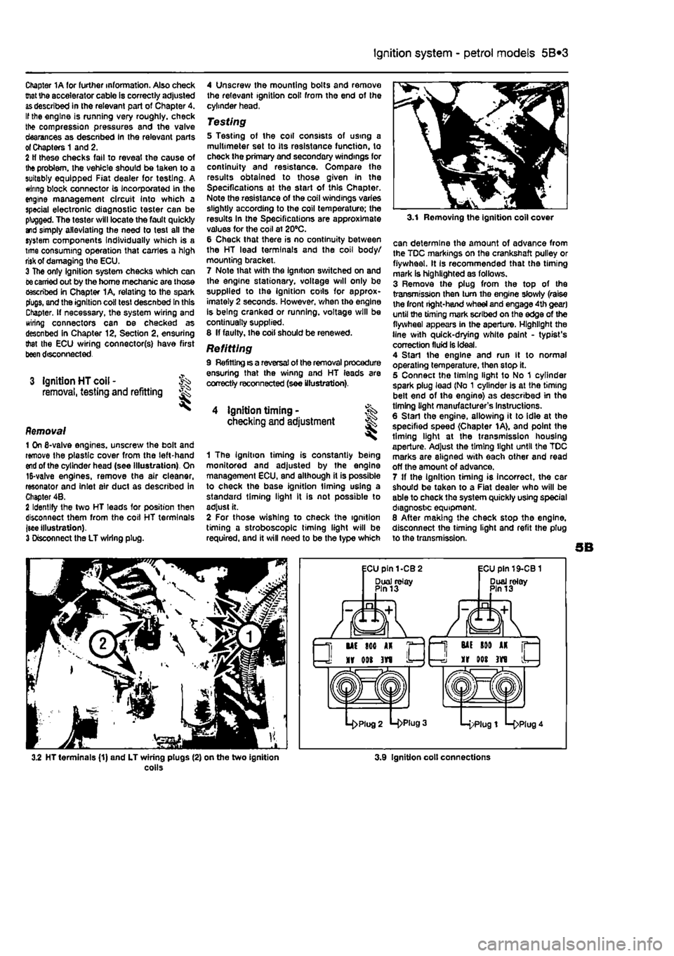
Removal 1 On 6-valve engines, unscrew the boll and remove the plastic cover from the left-hand
end
of the cylinder head (see Illustration). On 15-valve engines, remove the air cleaner, resonator and Inlet air duct as described in Chapter 4B. 2 Identify the two HT leads for position then disconnect them from the coil HT terminals jsee illustration). 3 Disconnect the LT wiring plug.
4 Unscrew the mounting bolts and remove the relevant ignition coil from the end of the cylinder head,
Testing 5 Testing of the coil consists of using a multimeter set to its resistance function, to check the primary and secondary windings for continuity and resistance. Compare the results obtained to those given In the Specifications at the start of this Chapter. Note the resistance of the coil windings varies slightly according to the coil temperature; the results In the Specifications are approximate values for the coil at 20°C. 6 Check that there is no continuity between the HT lead terminals and the coil body/ mourning bracket. 7 Note that with the ignition switched on and the engine stationary, voltage will only be supplied to the ignition cotls for approx-imately 2 seconds. However, when tho engine is being cranked or running, voltage will be continually supplied. 8 If faulty, the coil should be renewed.
Refitting 9 Refitting ts a reversal of the removal procedure ensuring that the winng and HT leads are correctly reconnected (see illustration).
4 ignition timing • checking and adjustment
1 The Ignition timing is constantly being monitored and adjusted by the engine management ECU, and although it is possible to check the base ignition liming using a standard timing light It is not possible to adjust it. 2 For those wishing to check the ignition timing a stroboscope timing light will be required, and it will need to be the type which
3.1 Removing the ignition coll cover
can determine the amount of advance from the TDC markings on the crankshaft pulley or flywheel. It Is recommended that the timing mark is highlighted as follows. 3 Remove the plug from the top of the transmission then turn tho engine slowly (raise the front right-hand wheel and engage 4th gear) until the timing mark scribed on the edge of the flywheel appears in the aperture. Highlight the line with quick-drying white paint - typist's correction fluid is ideal. 4 Start the engine and run It to normal operating temperature, then stop it. 5 Connect the timing light to No 1 cylinder spark plug lead (No 1 cylinder Is at the timing belt end of the engine) as described in the timing light manufacturer's Instructions. 6 Start the engine, allowing it to idle at the specified speed (Chapter 1A), and point the timing light at the transmission housing aperture. Adjust the timing light until the TDC marks are aligned with each other and read off the amount of advance. 7 If the ignition timing is incorrect, the car should be taken to a Fiat dealer who will be able to check the system quickly using special diagnostic equipment. 8 After making the check stop the engine, disconnect the timing light and refit the plug to the transmission.
3.2 HT terminals (1) and LT wiring plugs (2) on the two ignition colls 3.9 Ignition colt connections
Page 158 of 225
6*1
Chapter 6
Clutch
Contents
Clutch - adjustment Clutch assembly - removal, inspection and refitting Clutch cable • removal and refitting Clutch hydraulic system - bleeding
Degrees of difficulty
2 Clutch master cylinder • removal and refitting 5 7 Clutch release mechanism - removal, Inspection and refitting 8 3 Clutch slave cylinder - removal and refitting 6 4 General information 1
Easy, suitable for
novice with little experience oi^
Faidy easy,
suitable for beginner
with
^
some
experience
Fairly difficult, suitable
for
competent ^
DIY
mechanic ^
Difficiit, suitable for ^ experienced DIY JR mechanic ^
V<*y difficult,
jk
suitable
for expert
DIY
« or professional ^
Specifications
General Type
Clutch pedal travel (cable-operated mechanism)
Friction plate diameter 8-valve petrol engines 16-valve petrol engines Diesel engines
Torque wrench setting Pressure plate retaining bolts
Single dry plate with diaphragm spring, cable- or hydraullcally-operated according to model 140.0 ± 5.0 mm
181.5 mm 190.0 mm 200.0 mm
Nm Ibf ft 16 12
1 General information
Vehicles with manual transmission are fitted with a pedal operated single dry plate clutch system. When the clutch pedal is depressed, effort is transmitted to the clutch release mechanism either mechanically by means of a cable, or hydraullcally by means of a master
2.5 Clutch cable adjustment
cylinder and slave cylinder. The release mechanism transfers effort to Ihe pressure plate diaphragm spring, which withdraws the pressure plate from the flywheel and releases the driven plate-Where applicable, the hydraulic fluid employed in the clutch system is the same as that used in the braking system, hence fluid is supplied to the master cylinder from a tapping on the brake fluid reservoir. The clutch hydraulic system must be sealed before work Is carried out on any of its components and then on completion, topped up and bled to remove any air bubbles.
2 Clutch - % adjustment §§ ^
Note: This procedure applies to models fitted with a cable-operated dutch
release
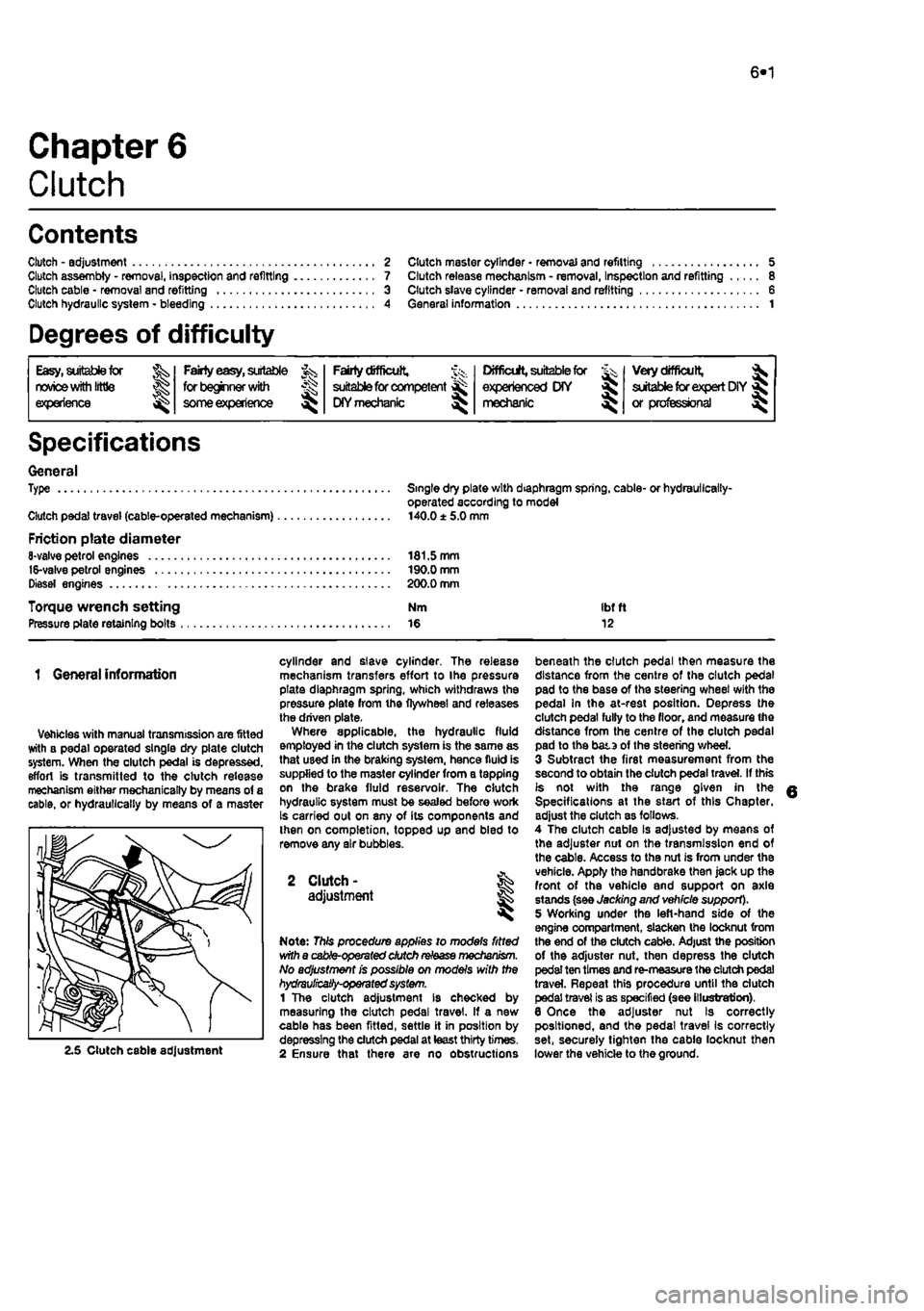
mechanism. No adjustment is possible on models with the hydrauHcaSy-operated system. 1 The clutch adjustment Is checked by measuring the clutch pedal travel. If a new cable has been fitted, settle it in position by depressing the clutch pedal at least thirty times. 2 Ensure that there are no obstructions
beneath the clutch pedal then measure the distance from the centre of the clutch pedal pad to the base of the steering wheel with the pedal In the at-rest position. Depress the clutch pedal fully to the floor, and measure the distance from the centre of the clutch pedal pad to the bata of the steering wheel. 3 Subtract the first measurement from the second to obtain the clutch pedal travel. If this is not with the range given in the Specifications at the start of this Chapter, adjust the clutch as follows. 4 The clutch cable Is adjusted by means of the adjuster nut on the transmission end of the cable. Access to the nut is from under the vehicle. Apply the handbrake then jack up the front of the vehicle and support on axle stands (see Jacking and vehicle support). 5 Working under the left-hand side of the engine compartment, slacken the locknut from the end of the clutch cable. Adjust the position of the adjuster nut. then depress the clutch pedal ten times and re-measure the dutch pedal travel. Repeat this procedure until the clutch pedal travel is as specified (see illustration). 6 Once the adjuster nut Is correctly positioned, and the pedal travel Is correctly set, securely tighten the cable locknut then lower the vehicle to the ground.
Page 159 of 225
6*2 Clutch
3 Clutch cable -removal and refitting
Note: This procedure applies to models fitted with a cabfe-opemted dutch
release mechanism.
Removal 1 Remove the battery and tray as described In Chapter SA. If necessary, also remove the Inlet air ducting for Improved access as described In the relevant part of Chapter 4. 2 Unscrew the adjustment locknut and adjuster nut from the end of the cable fitting, (hen release the inner and outer cables from the transmission housing. Note the position of the damper biock. 3 Working Inside the vehicle, unhook the inner cable from the top of the clutch pedaL 4 Returning to the engine compartment, unscrew the nuts securing the outer cable to the bulkhead, then withdraw the cable assembly from the engine compartment. Refitting 5 Apply a smear of multi-purpose grease to the cable end fittings, then pass the cable through the bulkhead. Refit and tighten the nuts. 6 Inside the vehicle hook the inner cable onto the top of the clutch pedal. 7 in the engine compartment, attach the outer cable to the transmission housing and refit the damper block and nuts lo Ihe inner cable end. fi Adjust the cable as described in Section 2. 9 Refit the air ducting and battery with reference to Chapters 4 and 5A
4 Clutch hydraulic system -
i
Note: This procedure applies to models fitted with the hydraulicalty-operated clutch release mechanism.
A
Warning: Hydraulic fluid Is poisonous; thoroughly wash off spllfs from bare skin without delay. Seek Immediate medical advice If any fluid is swallowed or gets into the eyes. Certain types of hydraulic fluid are Inflammable and may ignite when brought into contact with hot components; when servicing any hydraulic system, It is safest to assume that the fluid IS Inflammable, and to take precautions against the risk of fire as though ft were petrof that was being handled. Hydraulic fluid Is an effective paint stripper and will also attack many plastics. If spillage occurs onto painted bodywork or fittings, ft should be washed off Immediately, using copious quantities of fresh water. It Is also hygroscopic - It can absorb moisture from the air, which then renders it useless. Old fluid may have
suffered contamination, and should never be re-used. When topping-up or renewing tho fluid, always use tha recommended grade, and ensure that It comes from a new seated container. General information 1 Whenever the clutch hydraulic lines are disconnected for service or repair, a certain amount of air will enter the system. The presence of air In any hydraulic system will Introduce a degree of elasticity, and in the clutch system this will translate into poor pedal feel and reduced travel, leading to inefficient gear changes and even clutch system failure. For this reason, the hydraulic lines must be sealed using hose clamps before any work la carried out and then on completion, topped up and bled to remove any air bubbles. 2 To seal off Ihe hydraulic supply to tha clutch slave cylinder, fit a proprietary brake hose clamp to the flexible section of the hose located over the transmission and tighten it securely. It will be necessary to remove the battery and battery tray to access the hose. 3 The most effective way of bleeding the clutch hydraulic system is to use a pressure brake bleeding kit. These are readily available in motor accessories shops and are extremely effective: the following sub-section describes bleeding the clutch system using such a kit. The alternative method is to bleed the system by depressing tho clutch pedal • refer to Chapter 9. Section 11, for details of this method.
Bleeding 4 Remove the protective cap from Ihe bleed nipple on the slave cylinder. Access can be improved by removing the battery and tray with reference to Chapter 5A. 5 Fit a ring spanner over the bleed nipple head, but do not slacken it at this point. Connect a length of dear plastic hose over the nipple and insert the other end into a clean container. Pour hydraulic fluid into the container, such that the end of the hose is covered. 6 Following the manufacturer's instructions, pour hydraulic fluid into the bleeding kit vessel 7 Unscrew the vehicle's fluid reservoir cap, then connect Ihe bleeding kit fluid supply hose to the reservoir. 8 Connect the pressure hose to a supply of compressed air - a spare tyre is a convenient source. Caution: Check that the pressure In the tyre does not exceed the maximum supply pressure quoted by the kit manufacturer, let soma sir escape to reduce the pressure, if necessary. Gently open the air valve and allow the air and fluid pressures to equalise. Check that there ere no teaks before proceeding. 9 Using the spanner, slacken the bleed pipe nipple until fluid and air bubbles can be seen to flow through the tube, into the container.
Maintain a steady flow until the emerging fluid la free of air bubbles; keep a watchful eye on the level of fluid in the bleeding kit vessel and the vehicle's fluid reservoir • if it Is allowed to drop too low, air may be forced into the system, defeating the object of the exercise. To refill the vessel, turn off the compressed air supply, remove the lid and pour In en appropriate quantity of clean fluid from a new container - do not re-use the fluid collected in the receiving container. Repeat as necessary until the ejected fluid is bubble-free. 10 On completion, pump the olutch pedal several times to assess its feel and travel. If firm, constant pedal resistance is not felt throughout the pedal stroke, it i6 probable that air Is still present in the system - repeat the bleeding procedure untii the pedal feel is restored. 11 Depressurise the bleeding kit and remove it from the vehicle. At this point, the fluid reservoir may be over-full; the excess should be removed using a clean pipette to reduce the level to the MAX mark. 12 Tighten the bleed pipe nipple using the spanner and remove the receiving container. Refit the protective cap. 13 On completion, assess the feel of the clutch pedal; if it exhibits any sponginess or looseness, further bleeding may be required. 14 Where removed, refit the battery and tray. 15 Finally, road test the vehicle and check the operation of the clutch system whilst changing up and down through the gsar9. whilst pulling away from a standstill and from a hill start.
5 Clutch master cylinder - & removal
and
refitting 5 S Note: This procedure applies to models
fitted
with the hydraulically-operated dutch
release
mechanism. Note: Refer to the warning at Ihe beginning
of
Section 4 regarding the hazards of
working
with hydraulic fluid.
Removal 1 Disconnect the battery negative terminal (refer lo Disconnecting the battery in the Reference Section of this manual). 2 Remove the air cleaner and air ducting as described in the relevant Part of Chapter 4. 3 For improved access on petrol engine models, remove the alternator as described In Chapter 5A. 4 Fit a brake hose clamp to the hose between the hydraulic fluid reservoir and the clutch master cylinder. Alternatively syphon ail the fluid from the reservoir. 5 Disconnect the fluid supply hose at the master cylinder, then unscrew the union nut and disconnect the hydraulic pipe from the cylinder outlet. Be prepared for some fluid loss by placing some rags beneath the master cylinder.
Page 160 of 225
Clutch 6*3
6 WorWng inside the vehicle, extract the split pin and remove the washer securing the master cylinder pushrod to the clutch pedal. Dsoonnect the pushrod from the pivot. 7 Have an assistant support the master cylinder In the engine compartment, then unscrew the mounting bolts. Withdraw the master cylinder from the engine compartment, 8 II is not possible to obtain an overhaul kit from Flat however some motor factors may be abls to supply one. Follow the Instructions with the repair kit if obtained.
Refitting 9 Refit the clutch master cylinder by following ihe removal procedure In reverse, noting the following. a) Apply a
Utile
high-melting point grease to the clutch pedal pivot. b) Tighten the mounting bolts and union nut securely. cj Fit a new split pin to the pushrod. d) Where removed, refit the alternator
as
described In Chapter 5A e) On completion bleed the clutch hydraulic system as descnbed in Section
A.
7 Clutch assembly -
removal,
inspection
and
refitting
S Clutch slave cylinder-removal and refitting
Note: This procedure applies to models fitted
ivrth
the hydraulically-operated clutch release mechanism. Note: Refer to the warning at the beginning
of
Section A regarding the hazards of working
with
hydraulic fluid.
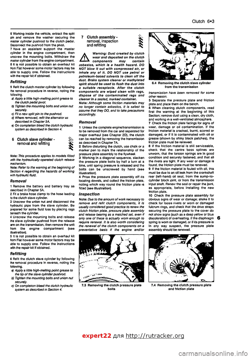
Removal 1 Remove the battery and battery tray as described in Chapter 5A. 2 Fit a brake hose clamp to tha hose leading to the clutch slave cylinder. 3 Unscrew the union nut and disconnect the hydraulic pipe from the slave cylinder. Be prepared for some fluid loss by placing rags beneath the cylinder. 4 Unscrew the mounting bolts and release the slave cylinder pushrod from the release am on the transmission, then remove the unit from the engine compartment (see Illustration). 5 It is not possible to obtain an overhaul kit from Flat however some motor factors may be able to supply one. Follow tha instructions with the repair kit if obtained.
Refitting 6 Refit the clutch slave cylinder by following the removal procedure In reverse, noting the following. a) Apply a little high-melting point grease to the tip of the slave cylinder pushrod. b) Tighten the mounting bolts and union nut securely. c) On completion bleed the dutch hydraulic system as described in Section A.
A
Warning: Dust created by clutch wear and deposited on the clutch components may contain asbestos, which Is a health hazard. DO NOT blow it out with compressed air, or inhale any of it. DO NOT use petrol or petroleum-based solvents to clean off the dust. Brake system cleaner or methylated spirit should be used to flush the dust Into a suitable receptacle. After the clutch components are wiped clean with rags, dispose of the confam/nafed rags and cleaner In a sealed, marked container. Note: Although some friction materials may no longer contain asbestos, it is safest to assume that they DO. and to take precautions accordingly.
Removal 1 Unless the complete engine/transmission is to be removed from the car and separated for major overhaul (see Chapter 2D), Ihe clutch can be reached by removing the transmission as descnbed in Chapter 7A, 2 Before disturbing the clutch, use chalk or a marker pen to mark the relationship of the pressure plate assembly to the flywheel. 3 Working In a diagonal sequence, slacken the pressure plate bolts by half a turn at a time, until spring pressure Is released and the bolls can be unscrewed by hand (see Illustration). 4 Prise the pressure piate assembly off its locating dowels, and collect the friction plate, noting which way round the friction plate is fitted (see Illustration).
Inspection Note: Due to the amount of work necessary to remove and refit clutch components, It is usually considered good practice to renew the clutch friction plate, pressure plate assembly and release bearing as a matched set. even if only one of these is actually worn enough to require renewal. It Is also worth considering the renewal of the clutch components on a preventative basis if the engine and/or
6.4 Removing the clutch slave cylinder from the transmission fransmj'ss/on have been removed for some other reason. 5 Separate the pressure plate and friction plate and place them on the bench. 6 When cleaning clutch components, read first the warning at the beginning of this Section; remove dust using a clean, dry cloth, and working in a well-ventilated atmosphere. 7 Check the friction plats facings for signs Of wear, damage or oil contamination. If the friction material is cracked, burnt, scored or damaged, or if It is contaminated with oil or grease (shown by shiny black patches), the friction plate must be renewed. 8 If tho friction material Is still serviceable, check that the centre boss splines are unworn, that the torsion springs are In good condition and securely fastened, and that all the rivets are tight. If any wear or damage is found, the friction plate must be renewed. 9 If the friction material is fouled with oil, this must be duo to an oil leak from the crankshaft rear (left-hand) oil seal, from the sump-to-cytinder block joint, or from the transmission Input shaft. Renew tha soal or repair the Joint, as appropriate, before Installing the new friction plate. 10 Check tha pressure plate assembly for obvious signs of wear or damage; shake it to check for looss rivets or worn or damaged fulcrum rings, and check thai the drive straps securing the pressure plate to the cover do not show signs (such as a deep yellow or blue discoloration) of overheating. If the diaphragm spring is worn or damaged, or if its pressure is In any way suspect, the pressure plate assembly should be renewed.
7.3 Removing the clutch pressure plate bolts 7.4 Removing the clutch pressure plate and friction plate
expert22 {
a http://rutracker.org
Page 166 of 225
7B«1
Chapter 7 Part B:
Automatic transmission
Contents
Accelerator pedal micro-switch(es) - checking and adjustment II Automatic transmission filter and fluid change See Chapter 1A Automatic transmission fluid level check See Weekly checks Automatic transmission • overhaul 12 Automatic transmission • removal and refining 2 Bectro-magnetic clutch - removal, inspection and refitting 3 BectrO'fnagnetic clutch brushes- removal, inspection and refitting . 4
Electronic control unit - removal and refitting 5 Gear selector cable - adjustment 6 Gear selector cable - removal and refitting 9 General information 1 Kickdown cable - adjustment 7 Kickdown cable - removal and refitting 6 Transmission oil pump - removal and refitting 10
Degrees of difficulty
Easy,
suitable for novice
with
ittle experience ^
Party
easy,
suitable for beginner
with
^r someexperienoe ^
Faiily
difficult,
^ suitable
for
competent
DIY mechanic
^
Difficult, suitable
for fe, experienced DIY >8J mechanic
Verydfficult, ^
suitable
for
expert DIY
or professional ^
Specifications
General Type Ratios (at transmission): Lowest Highest Final drive
Torque wrench settings Esnh cable Control unit Sectro-magnetic clutch to flywheel Transmission-to-engine bolt/nut ..
ECVT (Electronic Continuously Variable Transmission)
2.503 0.497 4.647:1
Nm Ibftt 14 10 5 4 34 25 85 63
1 Genera) information
I The automatic transmission fitted is designated ECVT (Electronic Continuously Variable Transmission). The main components
01
the transmission are an electro-magnetic dutch, a variable-ratio coupling, a final drive/ differential unit, and the associated control mechanisms (see illustrations overleaf) 2 The variable-ratio coupling consists of two pulleys and a flexible metal drivebelt. The effective diameter of the two pulleys can be varied to provide different transmission ratios between them. 3 During normal driving, the transmission automatically selects the ratio giving the best
compromise between economy and speed. When the driver depresses the accelerator pedal to the floor, a kickdown effect is provided, and the transmission selects a lower ratio for improved acceleration. 4 The gear selector control resembles that fitted to conventional automatic transmissions. The control positions are as follows: P (Parking) The transmission is mech-anically locked by the engage-ment of a pawl with a toothed segment on the driven pulley. R (Reverse) Reverse gean's engaged, N (Neutral) The transmission is In neutral. D (Drive) Normal driving position. Trans-mission ratio is varied automat-ically to suit prevailing speed and load.
L (Low) Prevents the transmission
moving into high ratios. Provides maximum acceleration end maximum engine braking. 5 The engine can only be started In positions P and N. A warning buzzer sounds If the selector is in any position other than P when the ignition is switched off or when the driver's door is opened. 6 The electro-magnetic clutch consists of a driving element boiled to the engine flywheel, and a driven element spiined to the transmission Input shaft. The degree of coupling between the (wo elements Is determined by the intensity of a magnetic field generated by a current passing through windings in the driven element. The magnetic field acts on a layer of metallic powder between the driving and driven elements. When no magnetic field is present, the powder is loose and the two elements are effectively
Page 169 of 225
7B*4 Automatic transmission
2 Automatic transmission - ^ removal and refitting St
Removal 1 Select a solid, level surface to park the vehicle upon. Give yourself enough space to move around it easily. Apply the handbrake then jack up the front of the vehicle and support on axle stands (see Jacking and vehicle support). Remove both front wheels, 2 Remove the battery and mounting tray as described In Chapter 5A. 3 Remove the air cleaner and air inlet duct as described In Chapter 4A. 4 Disconnect the kickdown cable at the sector on the throttle housing and detach It from the mounting on the camshaft cover. Also release the cable from the support on the left-hand end of the cylinder head. 5 Disconnect the wiring connectors on the transmission. 6 Disconnect the fluid inlet and outlet Unas from the heat exchanger on top of the transmission. 7 Pull the fluid level dipstick from Its tube on the front of the transmission and tape over the top of the tube to prevent dirt entry. 8 Unscrew and remove the retaining pin and disconnect the speed selector cable from the top of the transmission. 9 Unscrew the upper bolt securing the starter motor to the transmission. 10 Unscrew the upper bolts securing the transmission to the engine. 11 Support the weight of the engine using a hoist attached to the engine lifting eyes, or alternatively UBO a trolley jack and block of wood beneath the engine, 12 Remove the screws and remove the front wheel arch liner from under the left-hand wheel arch. 13 Unscrew the nut securing the earth cablo to the transmission. 14 Using a punch drive out the roll pins securing both driveshafts to the final drive output shafts. 15 Unscrew and remove the bolts securing the left-hand swivel hub assembly to the front suspension strut, then separate the components and support the swivel hub on an axle stand. 16 Move the swivel hub assembly outwards and slide the inner end of the driveshaft from the splines on the transmission output shaft. Support the shaft away from the transmission to prevent damage to the gaiters. 17 Unscrew the lambdafoxygen sensor from the exhaust downpipe and position it In a safe place to prevent damage. 18 Unscrew ihe nuts securing the downpipe to Ihe exhaust manifold, then lower It and suppon on an axle stand. Recover the gasket. 19 Unscrew the knurled nut and disconnect the speedometer cable from the top of the final drive housing.
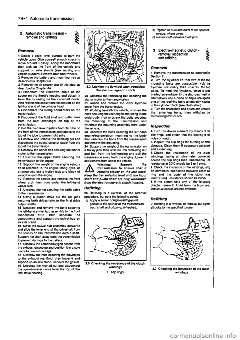
3-2 Locking the flywheel when removing the electromagnetic clutch 20 Unscrew the remaining bolt securing the staner motor to the transmission 21 Unbolt and remove Ihe lower flywheel cover from the transmission. 22 Working beneath the vehicle, unscrew the bolts securing the rear engine mounting to the underbody then unscrew the bolts securing the mounting lo the transmission and withdraw the mounting assembly from under the vehicle. 23 Unscrew the bolts securing the left-hand engine/transmission mounting to the body thon unscrew the bolts from the transmission and remove the mounting. 24 Support the weight of the transmission on a trolley jack then unscrew the remaining nut and bolt from the bellhouslng and pull the transmission away from the engine. Lower it and remove from under the vehicle.
A
Warning: Support the transmission to ensure that It remains steady on the Jack head. Keep the transmission level until the Input shaft and pump shaft are fully withdrawn from the electromagnetic clutch housing.
Refitting 25 Refitting is a reversal of the removal procedure, but note the following points. a} Apply a smear of high-melting-point grease to the splines of the transmission input shaft and oil pump driveshaft.
3.6 Checking the resistance of the clutch windings 1 Slip rings
0) Tighten all nuts and bolts to the
specified
torque, where given, c) Renew both driveshaft roll pins.
3 Electro-magnetic clutch • & removal, inspection 5. and refitting ^
Removal 1 Remove Ihe transmission as described n Section 2. 2 Turn the flywheel so that two of the lour mounting bolts are accessible, Hold tha flywheel stationary then unscrew Ihe tvrt bolts. To hold the flywheel, Insert a wida bladed screwdriver In the ring gear teeth or alternatively use a piece of angle iron against one of the retaining bolts temporarily Inserted in the cylinder block (see illustration). 3 Turn the crankshaft half a turn and unscrew the remaining bolts, then withdraw the electromagnetic clutch.
Inspection 4 Turn the driven element by means of tha slip rings, and check that the bearing is not noisy or rough. 5 Inspect the slip rings for burning or other damage. Clean them if necessary using fid and a clean rag. 6 Check the resistance of the clutch windings, using an ohmmetor connected across the slip rings (see Illustration). The resistance at 20*0 should be 2 to 4 ohms. 7 Check the Insulation of the windings, using an ohmmeter connected between either sip ring and the body of the clutch (see illustration). Resistance should be Infinity. 8 If the clutch fails any of the foregoing checks, renew it. Apart from the brush gear, Individual spares are not available.
Refitting 9 Refitting is a reversal of removal but tighten all bolts to the specified torque.
windings
Page 171 of 225
7B*6 Automatic transmission
Gear selector cable -adjustment
1 Remove the battery and tray as described In Chapter 5A for access to the transmission. 2 Disconnect the selector cable from the lever on Ihe transmission. 3 Move the selector fever inside the vehicle to the N (Neutral) position, then move the lever on the transmission to Its central (Neutral) position. Locate the cable end over the lever. If the cable end fitting does not line up exactly with the hole In Ihe lever, loosen the adjustment nut and reposition the end fitting. 4 With the adjustment correct reconnect tha cable to the lever, then move the selector lever to the P (Park) position. Check that the lever on the transmission has also moved to the P position. 6 Refit the battery and tray as described in Chapter 5A. 6 Road test the vehicle, and check for correct operation in all selector lever positions.
9 Gear selector cable -removal and refitting at
7 Inside the vehicle disconnect the selector cable from the bottom of the selector lever (hen remove it from the support bracket, a Withdraw the cable into the engine compartment, and remove it.
Refitting 9 Refitting is a reversal of removal, but adjust the cable as described in Section 8. 10 Check that It is only possible to start the engine in positions P and N. Reposition the selector lever switch If necessary. 11 Road test the vehicle, and check for correct operation In ell selector lever positions.
10 Transmission oil pump - & mnvtiifll rAtiMlitA removal a/id refitting
Removal 1 Using an Allen key. unscrew the screw and remove the selector lever knob from the lever. 2 Remove the oddment tray and the ashtray. 3 Remove the screws and withdraw the centre console and selector mechanism cover. 4 Unscrew the mounting screws, slightly lift the centre console, then disconnect the wiring and remove the console, 5 Remove the battery and tray as described in Chapter 5A for access to the transmission, 6 Disconnect the selector cable from the lever on the transmission.
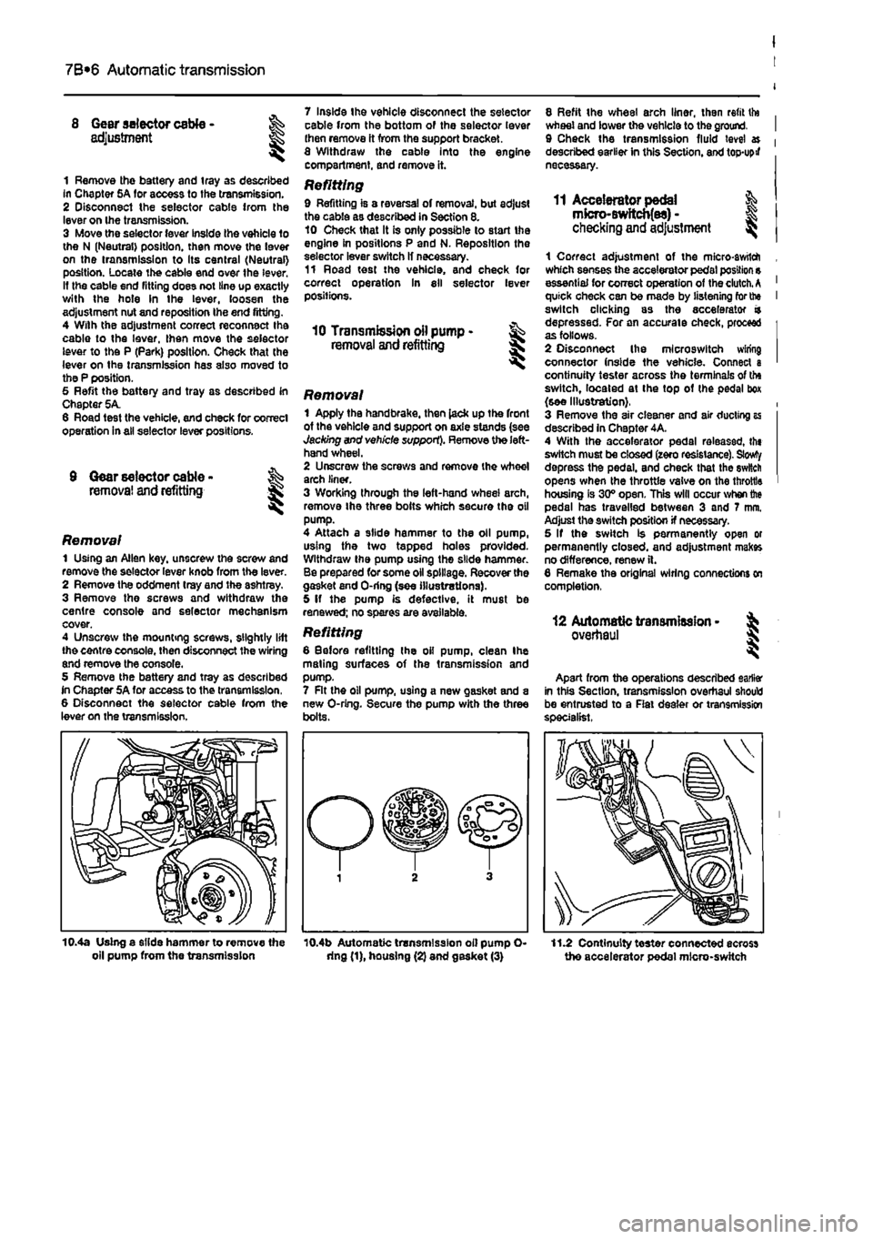
Removal 1 Apply the handbrake, then lack up the front of the vehicle and support on axle stands (see Jacking and vehicle support). Remove the left-hand wheel. 2 Unscrew the screws and remove the wheel arch liner. 3 Working through the left-hand wheel arch, remove Ihe three bolts which secure the oil pump. 4 Attach a slide hammer to the oil pump, using the two tapped holes provided. Withdraw the pump using the slide hammer. Be prepared for some oil spillage. Recover the gasket end O-ring (see illustrations). 5 If the pump is defective, it must be renewed; no spares are available.
Refitting 6 Before refitting Ihe oil pump, clean Ihe mating surfaces of the transmission and pump. 7 Rt the oil pump, U9ing a new gasket and a new O-ring. Secure the pump with the three bolts.
8 Refit the wheel arch liner, then refit tto wheel and lower the vehicle to the ground. 9 Check the transmission fluid level » described earlier in this Section, and top-upif necessary.
11 Accelerator pedal & mfcro-Bwftcb(es) -checking
and
adjustment ^
1 Correct adjustment of the micro-awtlch which senses the accelerator pedal position s essential for correct operation of the clutch.
A
quick check can be made by listening for the switch clicking as the accelerator a depressed. For an accurate check, proceed as follows. 2 Disconnect Ihe mlcroswitch wiring connector (nside the vehicle. Connect a continuity tester across the terminals of the switch, located at the top of (he pedal box (see Illustration}. 3 Remove the air cleaner and air ducting as described in Chapter 4A. 4 With the accelerator pedal releassd, th« switch must be closed (zero resistance). Slowty depress the pedal, and check that the switch opens when the throttle valve on the throttle housing is 30° open. This will occur when the pedal has travelled between 3 and 7 mm. Adjust the switch position if necessary. 5 If the switch is permanently open or permanently closed, and adjustment makes no difference, renew ft. 6 Remake the original wiring connections on completion,
12 Automatic transmission -overhaul
Apart from the operations described earlier in this Section, transmission overhaul should be entrusted to a Rat dealer or transmission specialist.
10.4a Using a slide hammer to remove the oil pump from the transmission 10.4b Automatic transmission oil pump O-dng (1), housing (2) and gasket (3) 11.2 Continuity tester connected ecross the accelerator pedal micro-switch
Page 190 of 225
Suspension and steering 10*2
Torque wrench settings (continued) Nm ibt ft Rasr suspension Damper lower securing bolt 95 70 Damper upper securing bolt 60 44 Handbrake cable support bracket-to-trailing arm screws 15 11 Hub nut 280 207 Trailing arm securing bolt 150 111 Steering Ignition switch/steering column lock securing bolts 4 3 Steering column mounting bolts 55 41 Steering gear mounting bolts 70 52 Steering wheel nut' 50 37 Subframe-to-body bolts 110 81 Track-rod end to hub carrier 40 30 Unlversaijointclampbolts 20 15 Roadwheels Roadwheel bolts 85 63 * Use a new nut
1 General information
Front suspension The front suspension is independent, comprising transverse lower wishbones, coil spring-over-damper strut units and an anti-roll bar. The hub carriors are bolted to the base of the stmt units and are linked to the lower arms by means ot balliotnts. The entire front suspension assembly is mounted on a subframe, which is In turn botted to the vehicle body.
Rear suspension The rear suspension incorporates a torsion beam axle, trailing arms, coil springs and separate telescopic dampers. In addition, a rear anil-roll bar is fitted to certain models. The components form a discrete sub-assembly which can be unboiled from the underside of the vehicle separately or as a complete unit.
Steering The two-piece steering shaft runs in a tubular column assembly, which is bolted to a bracket mounted on the vehicles bulkhead. The shaft Is articulated at its lower end by means of a universal Joint, which is clamped to the steering shaft and the steering gear pinion by moans of clamp bolts. The steering gear is mounted on the engine compartment bulkhead, and is connected to the steering arms projecting rearwards from Ihe hub carriers. The track-rods are fitted with balljoints at their inner and outer ends, to allow for suspension movement, and are threaded to facilitate ad|ustment. Hydrauiically-assisted power steering ts fittod to some models. The hydraulic system is powered by a belt-driven servo pump, which is driven from the crankshaft pulley.
Certain models are fitted with an airbag system. Sensors built into the vehicle body are triggered in the event of a front end collision and prompt an Electronic Control Unll (ECU) to activate the airbag, mounted In the centre of the steering wheel and the facia. This reduces the risk of the front seat occupants striking the steering wheel, windscreen or facia during an accident.
A
Warning: For safety reasons, owners are strongty advised to entrust to an authorised Flat dealer any work which involves disturbing the airbag system components. The airbag inflation devices contain explosive material and legislation exists to control their handling and storage, in addition, specialised test equipment Is needed to check that the airbag system Is fully operational following reassembly.
2 Front hub bearings -renewal *
Note: A balljoint separator tool, and a press or suitable alternative tools (see text) will be required for this operation. The bearing will be destroyed during the removal procedure.
Removal 1 Chock the rear wheels, apply the handbrake, then jack up the front of the vehicle and support on axle stands (see Jacking and vehicle support). Remove the appropriate roadwheel. 2 Remove the brake disc and caliper, with reference to Chapter 9. Note that the caliper body can remain bolted to its bracket: there is no need lo disconnect the brake fluid hose from the caliper. 3 With reference to Chapter 8. slacken and remove the driveshaft hub nut. 4 On models with ABS, unbolt the ABS wheel sensor, and remove the screw securing the
ABS sensor wiring to the hub carrier. Suspend the sensor away from the working ares, to avoid the possibility of damage. 5 With reference to Section 17, separate
th»
track-rod end from the hub carrier, using
a
suitable balljoint splitter. 6 Remove the two nuts from tho botts securing Ihe hub carrier to the base of th» suspension strut (refer to Section
3).
Withdrew the bolts and separate the top of hub earrtt from the strut. 7 Disconnect the outboard end of Ito driveshaft from the hub, as described durirg the driveshaft removal and refitting procedm in Chapter 8. Note: There is no naod fo disconnect the Inboard end of the
drivestett
from the transmission. Caution: Do not allow the end of tin driveshaft to hang down under its
own
weight, as this places strain on the
CV
joints; support the end of the shaft uskg wire or string. 8 Slacken and remove the nut and clamp bolt, then push the lower arm down anc separate the balljoint from the base of the tab carrier (see illustrations). 9 At this stage, it is recommended that
the bub
carrier be taken to a engineering workshop,
as
the hub and bearing should ideally be removed from the hub carrier using a hydraulic press
2.8a ... Slacken and remove the nut...