tow FIAT PUNTO 1999 176 / 1.G Workshop Manual
[x] Cancel search | Manufacturer: FIAT, Model Year: 1999, Model line: PUNTO, Model: FIAT PUNTO 1999 176 / 1.GPages: 225, PDF Size: 18.54 MB
Page 3 of 225
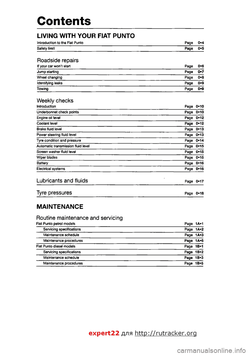
Contents
LIVING WITH YOUR FIAT PUNTO
Introduction to the Rat Punto Page 0-4 Safety lirstl Page 0*5
Roadside repairs If your car won't start Page 0*6 Jump starting Page 0*7 Wheel changing Page 0«8 Identifying teaks Page 0*9 Towing Page 0*9
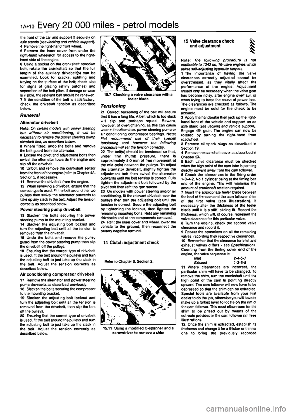
Weekly checks Introduction Page 0*10 Underbonnet check points Page 0»10 Engine oil level Page 0*12 Coolant level Page 0*12 Brake fluid level Page 0*13 Power steering fluid level Page 0"13 Tyre condition and pressure Page 0*14 Automatic transmission fluid level Page 0«1S Screen washer fluid level Page 0«1S Wiper blades Page 0*15 Battery Page 0*16 Electrical systems Page 0-16
Lubricants and fluids Page 0*17
Tyre pressures Page 0*18
MAINTENANCE
Routine maintenance and servicing Rat Punto petrol models Page 1A«1 Servicing specifications Page 1A«2 Maintenance schedule Page 1A«3 Maintenance procedures Page 1A«6 Fiat Punto diesei models Page 1B-1 Servicing specifications Page 1B«2 Maintenance schedule Page 1B«3 Maintenance procedures Page 1B«5
expert22 fl/ia http://rutracker.org
Page 9 of 225
o«8
Roadside repairs
Wheel changing
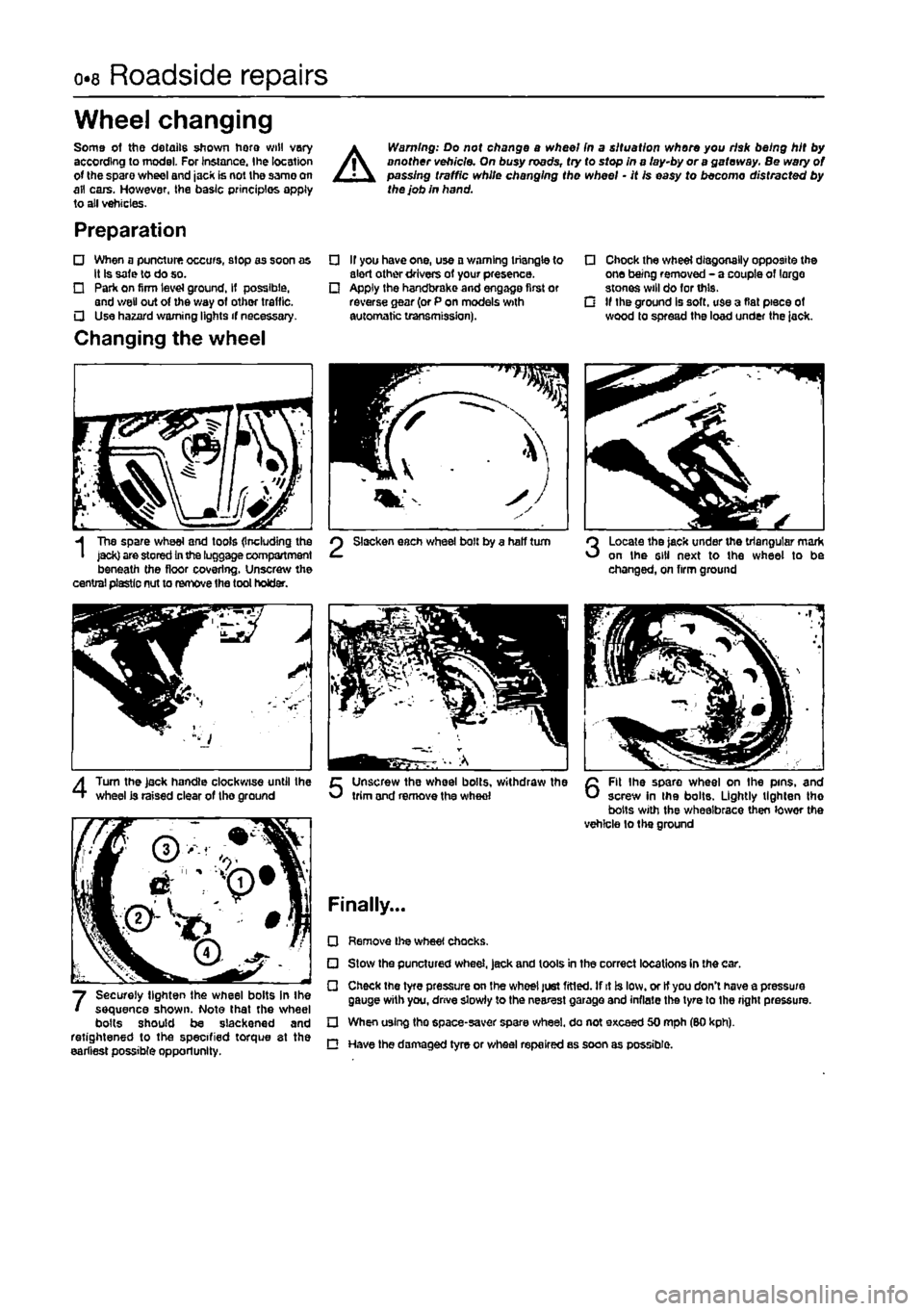
Some of the details shown horo will vary according to model. For Instance, the location of the spare wheel and jack is not the same on all cars. However, the basic principles apply to aii vehicles-
Preparation
• When a puncture occurs, stop as soon as it Is safe to do so. • Park on firm level ground. If possible, and v/etl out of the way of other traffic. • Use hazard warning lights if necessary.
Changing the wheel
A
Warning: Do not change a wheel (n a situation where you risk being hit by another vehicle. On busy roads, try to stop in a fay-by or a gateway. Be wary of passing traffic white changing the wheel - it Is easy to becomo distracted by the job in hand.
If you have one, use a warning triangle to alert other drivers of your presence. Apply the handbrake and engage first or reverse gear (or P on models with automatic transmission).
• Chock the wheel diagonally opposite the one being removed - a couple of largo stones will do for this. G If the ground is soft, use a flat piece of wood to spread the load under the iack.
I
Tbe spare wheel and tools (Including the jack) are stored
In
the luggage compartment beneath the floor covering. Unscrew the central plastic nut to remove the tool holder.
Slacken each wheel bolt by a half turn Locale the jack under the triangular mark on the 6)11 next to the wheel to be changed, on firm ground
4
Turn the Jack handle clockwise until the wheel Is raised clear of the ground Unscrew the wheel bolts, withdraw the trim and remove the whed
6
Fit Ihe spare wheel on the pins, and screw In the bolts. Lightly lighten tho bolts with the wheelbrace then lowor the vehicle to the ground
Finally...
Securely lighten the wheel bolts in Ihe sequence shown. Note that the wheel bolts should be slackened and retightened to the specified torque at the earliest possible opportunity.
• Remove l)>e wheel chocks.
• Stow the punctured wheel, jack and tools in the correct locations in the car. • Check the tyre pressure on the wheel just fitted. If it is low. or It you don't have a pressure gauge with you, drive slowly to the nearest garage and inflate the tyre to Ihe right pressure.
D When using tho space-saver spare wheel, do not exceed 50 mph (SO kph). C Have the damaged tyre or wheal repaired as soon as possible.
Page 10 of 225
Roadside repairs 0.9
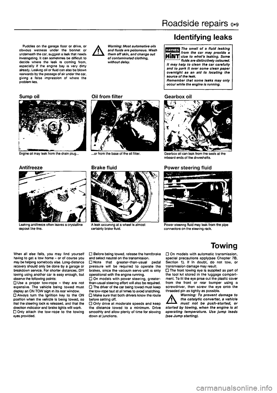
Puddles on the garage floor or drive, or obvious wetness under the bonnet or underneath the car, suggest a leak that needs Investigating. It can sometimes be difficult to decide where the leak is coming from, especially if the engine bay is very dirty already. Leaking oil or fluid can also be blown rearwards by the passage of air under the car, giving a false impression of where the problem lies.
A
Warning: Most automotive oils and fluids aro poisonous. Wash them off skin, and change out of contaminated clothing, without delay.
Identifying leaks
The smell of 0 fluid leaking from the car may provide a clue to what's leaking. Some fluids are distinctively coloured. It may help to clean the car carefully and to park It over some clean paper overnight as an aid to locating the source of the leak. Remember that some leaks may only occur while the engine is running.
Sump oil
Engine oil may leak from the drain plug...
Antifreeze
Leaking antifreeze often leaves a crystalline oeposit like this.
Oil from filter
A leak occurring at a wheel Is almost certainly brake fluid.
Gearbox oil
Gearbox oil can leak from the seals at the inboard ends of the drivoshafts.
Power steering fluid
Power steering fluid may leak from the pipe connectors on the steering rack.
When ail else falls, you may llnd yourself having to get a tow home - or of course you may be helping somebody else. Long-distance recovery should only be done by a garage or breakdown service. For shorter distances. OIY towing using another car is easy enough, but observe the following points: • Use a proper tow-rope - they are not expensive. The vehicle being towed must display an ON TOW sign in its rear window. • Always turn the Ignition key to the ON position when the vehicle is being towed, so that the steering lock is released, and that the direction indicator and brake lights will work. • Only attach the tow-rope to the towing eyes provided.
• Before being towed, release the handbrake and select neutral on the transmission. • Note that greater-then-usual pedal pressure will be required to operate the brakes, since the vacuum servo unit is only operational with the engine running. • On models with power steering, greater-than-usual steering effort will also be required. • The driver of the car being towed must keep the tow-rope taut at all times to avoid snatching. • Make sure that both drivers know the route before setting off. • Only dnve at moderate speeds and keep the distance towed to a minimum. Drive smoothly and allow plenty of time for slowing down at junctions.
Towing
• On models with automatic transmission, special precautions apply(see Chapter 7B. Section 1). If In doubt, do not tow, or transmission damage may result. • The front towing eye is supplied as part of the tool kit stored in the luggage compart-ment. To fit the eye pnse out the plastic cover from the front or rear bumper using a screwdriver, then screw the eye onto the threaded pin as tightly as possible.
A
Warning: To prevent damage to the catalytic converter, e vehicle must not be push'started, or started by towing, when the engine is at operating temperature. Use jump leads (see Jump starting).
Page 13 of 225
o*i2 Weekly checks
Engine oil level
Before you start • Make euro that your cor is on level ground. • Check ihe oil level oefore ihe cor is driven, or at least 5 minutes alter the engine has been switched off.
HHifffl If tho oil Is checked rTf"™^ Immediately after driving the IHlAIT vehicle,
some
of the oil will " remain In the upper engine components, resulting in on inaccurate reading on the dipstick!
The correct oil Modern engines place great demands on their oil. It Is very important that the correct oil for your car is used
Car Care • If you have to add oil frequently, you should check whother you have any oil leaks. Place some clean paper under the car overnight, and check for stains In the morning. If there are no leaks, the engine may be burning oil.
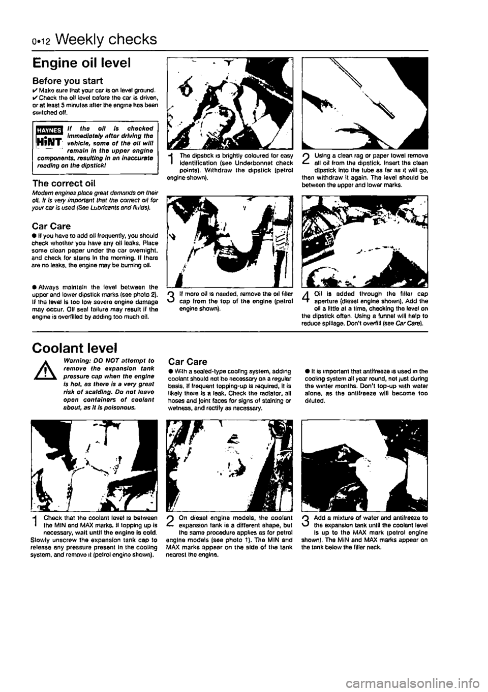
• Always maintain the level between the upper and lower dipstick marks (see pholo 2). If Ihe level Is too low
sqvoio
engine damage may oecur. Oil seal failure may result if tho engine is overfilled by adding too much oil.
I
Tho dipstick is brightly coloured for easy identification (seo Under bonnet check points). Withdraw the dipstick (petrol engine shown).
3
If more oil is needed, remove the oil filler cap Irom the top of the ongine (petrol engine shown).
SI i J
2
Using a clean rag or paper towel remove all oil from the dipstick. Insert the clean dipstick into the tube as far as it will go, then withdraw it again. The level should be between the upper and lower marks.
4
Oil Is added through the filler cap aperture (diesel engine shown). Add the oil a little at a time, checking the level on the dipstick often. Using a funnel will help to reduce spillage. Don't overfill (see Car Care).
Coolant level
A
Warning: DO NOT attempt to remove the expansion tank pressure cap when the engine is hot, as there is a very great risk of scalding. Do not leave open containers of coo/ant about, as It is poisonous.
Car Care • With a sealed-type cooling system, adding coolant should not be necessary on a regular basis. If frequent topping-up is required, it is likely there Is a leak. Check the radiator, all hoses and Joint faces for signs of staining or wetness, and roctify as necessary.
• It is important that antifreeze is used in the cooling system all year round, not just during the winter months. Don't top-up with water alone, as the antifreeze will become too diluted.
H Check that the coolant level is between I the MIN and MAX marks, il topping up is necessary, wait until tho engine is cold. Slowly unscrew the expansion tank cap to release any pressure present in the cooling system, and remove it (petrol engine shown).
2
On diesel engine models, Ihe ooolant expansion tank is a different shape, but Ihe same procedure applies as for petrol engine models (see photo 1). Tho MlN and MAX marks appear on the side of tlie tank neorosl the engine.
3
Add a mixture of water and antifreeze to the expansion tank until the coolant level is up to the MAX mark (petrol engine shown), The MIN and MAX marks appear on the tank below the filler neck.
Page 29 of 225
ia.io Every 20 000 miles - petrol models
the front of the car and support It securely on axle stands (see Jacking and vehicle support}. 4 Remove the nght-hand front wheel. 5 Remove the inner cover from under the right-hand wheeiarch for access to the right-hand side of the engine. 0 Using a socket on the crankshaft sprocket boll, rotate the crankshaft so that the full length of the auxiliary drlvebelt(s) can be examined. Look for cracks, splitting and fraying on the surface of the belt: check also for signs of glazing (shiny patches) and separation of the belt plies. If damage or wear Is visible, the relevant belt should be renewed. 7 If the condition of the belt Is satisfactory, check Ihe drivebeit tension as described below.
Renewal
Alternator drivebeit Note: On certain models with power steering but without air conditioning, it will be necessary to remove the power steering pump drivebeit ffrst, as described below. 8 Where fitted, undo the bolts and remove the belt guard from the alternator. 9 Loosen the pivot and adjustment bolts then swivel the alternator towards the engine and slip off the drivebeit. 10 Unbolt and remove the crankshaft sensor from Ihe front of the engine (refer to Chapter 4A. Section 5, if necessary). 11 Remove the drivebeit from the engine. 12 When renewing a drivebeit. ensure that the correct type is used. Fit the belt around the two pulleys then swivel the alternator outwaids to take up any slack in the betL Adjust the tension correctly as described below. Power steering pump drivebeit 13 Slacken the bolts securing the power steering pump to the mounting bracket. 14 Slacken the adjusting bolt locknut and turn the adjusting boit until all the tension is removed from the drivebeit. 15 Undo the bolts and remove the pultey guard from the power steering pump then slip the drivebeit off (he pulleys. 18 Ensuring that the correct type of drivebeit is used, fit the belt around the pulleys and turn the adjusting bolt to just take up the slack in the belt. Adjust the tension correctly as described below. Air conditioning compressor drivebeit 17 Remove the alternator and power steering pump dnvebelts as described previously. 18 Slacken the bolts securing the compressor to the mounting bracket. 19 Slacken the adjusting bolt locknut and turn the adjusting bolt until alt the tension is removed from the drivebeit, then slip the belt off the pulleys. 20 Ensuring lhat the correct type of drivebeit is used, fit the belt around the pulleys and turn the adjusting bolt to just take up the slack In the belt. Adjust the tension correctly as described below.
15.7 Checking a valve clearance with a feeler blade
Tensioning 21 Correct tensioning of the belt will ensure that it has a long life. A belt which Is too slack will slip and perhaps squeal. Beware, however, of overtightening, as this can cause wear in the alternator, power steering pump or air conditioning compressor bearings. Note: Fiat recommend use of their special tensioning tool however the fallowing procedure will set the tension correctly. 22 The belt(s) should be tensioned so that, under firm thumb pressure, there is approximately 5.0 mm of free movement at the mid-point between the pulleys. To adjust the alternator drivebeit, slightly tighten the adjustment bolt then swivel the alternator outwards until tne beft tension Is correct. Fully tighten the adjustment bolt followed by the pivot bolt then refit the rpm sensor. 23 On models with power steering and/or air conditioning, fit the relevant drivebeit over the pulleys then turn the adjusting bolt until the tension is correct. Secure the adjusting bolt by tightening Ihe locknut, then tighten the remaining mounting bolts. Refit any remaining dnvebelts and all the components removed. 24 Refit the inner cover and wheel, lower the vehicle to the ground, then reconnect the battery negative terminal,
14 Clutch adjustment check
Refer to Chapter 8. Section 2.
15.11 Using a modified C-spanner and e screwdriver to remove a shim
15 Valve clearance check ^ and adjustment S
Note: The following procedure Is not applicable to 1242 cc,
16-vatve
engines which utilise self-adjusting hydraulic tappets. 1 The importance of having the valve clearances correctly adjusted cannot be overstressed, as they vitally affect the performance of the engine. Adjustment should only be necessary when the valve gear has become noisy, after engine overhaul, or when trying to trace the cause of power loss. The clearances are checked as follows. The engine must be cold for the check to be accurate. 2 Apply the handbrake then jack up the right* hand front of the vehicle and support on an axle stand (see Jacking and vehicle support). Engage 4th gear. The engine can now be rotated by turning the right-hand front road wheel. 3 Remove all spark plugs as described In Section 19. 4 Remove the camshaft cover as described In Chapter 2A. 5 Each valve clearance must be checked when the high point of the cam lobe is pointing directly upward away from the cam follower. 6 Check the clearances In the firing order 1-3-4-2. No
1
cylinder being at the timing bell end of the engine. This will minimise the amount of crankshaft rotation required. 7 Insert the appropriate feeler blade between the heel of the cam and the cam follower shim of the first valve (see illustration). II necessary alter the thickness of the feeler blade until it is a stiff, sliding fit. Record the thickness, which will, of course, represent the valve clearance for this particular valve. 8 Tum the engine, check the second valve clearance and record it. 9 Repeat the operations on all the remaining valves, recording their respective clearances. 10 Remember that the clearance for Inlet and exhaust valves differs • see Specifications. Counting from the timing cover end of the engine, the valve sequence is: tnlet 2-4-5-7 Exhaust 7-3-6-$ 11 Where clearances are incorrect, the particular shim will have to be changed. To remove the shim, turn the crankshaft until the high point of the cam Is pointing directly upward. The cam follower will now have to be depressed so that the shim can be extracted. Special tools are available from your Fiat dealer to do the job, otherwise you will have to make up a forked (ever to locate on the rim of the cam follower. This must allow room for the shim to be prised out by means of the cut-outs provided in the cam follower rim {see illustration). 12 Once the shim is extracted, establish its thickness and change It for a thicker or thinner one to bring the previously recorded
Page 30 of 225
Every 20 000 miles - petrol models ia-h
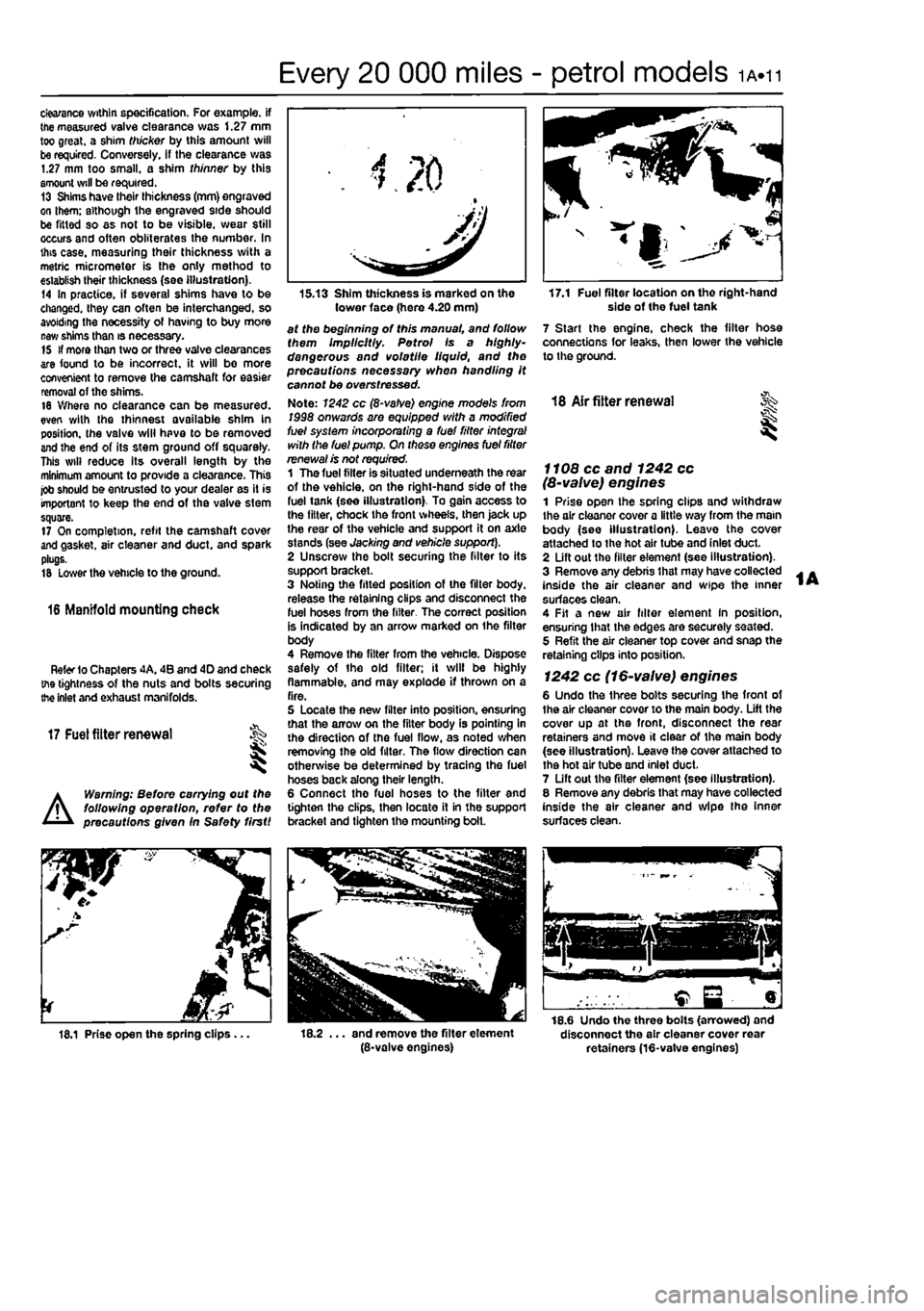
clearance within specification. For example, if the measured valve clearance was 1.27 mm too great, a shim thicker by this amount will be required. Conversely, if the clearance was 1.27 mm too small, a shim thinner by this amount will be required. 13 Shims have their thickness (mm) engraved on them; although the engraved side should be fitted so as not to be visible, wear still occurs and often obliterates the number. In this case, measuring their thickness with a metric micrometer is the only method to establish their thickness (see illustration). t4 In practice, if several shims have to be changed, they can often be interchanged, so avoiding the necessity of having to buy more new shims than is necessary. 15 If more than two or three valve clearances are found to be incorrect, it will be more convenient to remove the camshaft for easier removal of the shims. 16 Where no clearance can be measured, even with the thinnest available shim in position, the valve will have to be removed and the end of its stem ground off squarely. This will reduce its overall length by the minimum amount to provide a clearance. This job should be entrusted to your dealer as it is important to keep the end of the valve stem square. 17 On completion, refit the camshaft cover and gasket, air cleaner and duct, and spark plugs. 18 lower the vehicle to the ground.
16 Manifold mounting check
Refer
1O
Chapters 4A. 48 and 4D and check tne tightness of the nuts and bolts securing the inlet and exhaust manifolds.
17
Fuel
filter renewal I I
Warning: Before carrying out the !\ f°llow'n9 operation, refer to the precautions given In Safety firstI A
15.13 Shim thickness is marked on the tower face (here 4.20 mm) at the beginning of this manual, and follow them Implicitly. Petrol Is a highly-dangerous and volatile liquid, and the precautions necessary when handling it cannot be overstressed. Note: 1242 cc (8-vatve) engine mode's from 1998 onwards are equipped with a modified fuel system incorporating a fuel fitter integral with the fuel pump. On these engines fuel filter renewal is not required. 1 The fuel filter is situated underneath the rear of the vehicle, on the right-hand side of the fuel tank (see illustration). To gain access to the filter, chock the front wheels, then jack up the rear of the vehicle and support it on axle stands (see Jacking and vehicle support). 2 Unscrew the bolt securing the filter to its support bracket. 3 Noting the fitted position of the filter body, release the retaining clips and disconnect the fuel hoses from the filter. The correct position is indicated by an arrow marked on ihe filter body 4 Remove the filter from the vehicle. Dispose safely of the old filter; it will be highly flammable, and may explode if thrown on a fire. 5 Locate the new filter into position, ensuring that the arrow on the filter body is pointing in the direction of the fuel flow, as noted when removing the old filter. The flow direction can otherwise be determined by tracing the fuel hoses back along their length. 6 Connect the fuel hoses to the filter and lighten the clips, then locate it in the support bracket and tighten the mounting bolt.
17.1 Fuel filter location on tho right-hand side of the fuel tank 7 Start the engine, check the filter hose connections for leaks, then lower the vehicle to the ground.
18 Air fitter renewal
I
f f 08 cc and 1242 cc (8-valve) engines 1 Prise open the spring clips and withdraw the air cleaner cover a little way from the main body (see illustration). Leave the cover attached to the hot air tube and inlet duct. 2 Lift out the filter element (see illustration). 3 Remove any debris that may have collected inside the air cleaner and wipe the inner surfaces clean. 4 Fit a new air filter element In position, ensuring that the edges are securely seated. 5 Refit the air cleaner top cover and snap the retaining clips into position.
1242 cc (16-valve) engines 6 Undo the three bolts securing the front of Ihe air cleaner cover to the main body. Lift the cover up at the front, disconnect the rear retainers and move it clear of the main body {see illustration). Leave the cover attached to the hot air tube and inlet duct. 7 Lift out the filter element (see illustration). 8 Remove any debris that may have collected inside the air cleaner and wipe the inner surfaces clean.
18.1 Prise open the spring clips... . and remove the filter element (8-valve engines)
18.6 Undo the three bolts (arrowed) and disconnect the air cleaner cover rear retainers (16-vatve engines)
Page 42 of 225
ib.6 Maintenance procedures - diesel models
Every 5000 miles (7500 km) or 6 months
3 Engine oil and filter renewal it-
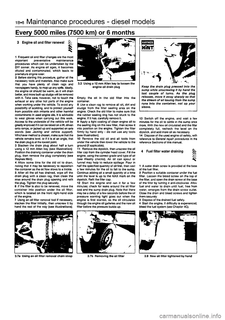
1 Frequent oil and filter changes are the most important preventative maintenance procedures which can be undertaken by the OlY owner. As engine oil ages, if becomes diluted and contaminated, which leads lo premature engine wear. 2 Befote starting this procedure, gather ail the necessary tools and materials. Also make sure that you have plenty of clean rags and newspapers handy, to mop up any splits. Ideally, the engine oil should be warm, as it will drain better, and more built-up sludge will be removed with it. Take care, however, not to touch the exhaust or any other hot parts of the engine when working under the vehicle. To avoid any possibility of scalding, and to protect yourself from possible skin irritants and other harmful contaminants in used engine oils, it is advisable to wear gloves when carrying out this woik. Access to the underside of the vehicle will be greatly improved if it can be raised on a lilt, driven onto ramps, or jacked up and supported on axle stands {see Jacking and vehicle support). Whichever method Is chosen, make sure that the vehicle remains level, or If it is at an angle, that Ihe drain plug is at the lowest point. 3 Slacken the drain plug about half a turn using a 12 mm Allen key (see Illustration) Position the draining container under the drain plug, then remove the plug completely (see Haynes Hint), 4 Allow some time for the oid oil to dram, noting that it may be necessary to reposition the container as the oil (tow slows to a trickle. 5 After all the oil has drained, wipe off the drain plug wilh a clean rag, then clean the area around the drain plug opening and refit the plug. Tighten the ptug securely. 6 If the filter is also to be renewed, move the container Into position under the oil filter, which Is located on the front right-hand side of the engine. 7 Using an oil filter removal tool if necessary, slacken the filter initially, then unscrew It by hand the rest of the way (see illustrations).
3.3 Using a 12 mm Allen key to loosen the engine oil drain plug
Empty the oil In (he old filter Into Ihe container. 8 Use a clean rag to remove all oil, dirt and sludge from the filter sealing area on the engine. Check the old lilter to make sure thai the rubber sealing ring has not stuck to the engine. If it has. carefully removo it. 9 Apply a light coating of clean engine oil to the sealing ring on the new filter, then screw it into position on the engine. Tighten the filter firmly by hand only • do not use any tools (see Illustration), 10 Remove Ihe old oil and all tools from under the vehicle then lower Ihe vehicle to the ground (If applicable). 11 Remove tho dipstick, then unscrew (he oil liiler cap from the cylinder head cover. Fill the engine, using Ihe correct grade and typo of oil (see Weekly checks). An oil can spout or funnel may help to reduce spillage Pour in half the specified quantity of oil first, then wait a few minutes for the oil to fall to the sump. Continue adding oil a smalt quantity at a time until Ihe level Is up to the MAX mark on the dipstick. Refit the filler cap. 12 Start the engine and run it for a tew minutes; check for leaks around the oil filter seal and the sump drain plug. Note that there may be a delay of a few seconds before the oil pressure warning light goes oul when the engine is first started, as the oil circulates through the engine oil galleries and the new oil filter before the pressure builds up.
Keep the drain plug pressed Into the sump while unscrewing It by hand the lost couple of turns. As the plug releases, move It away sharpty so that the stream of oil issuing from the sump runs Into the container, not up your sieeve.
13 Switoh off the engine, and wait a few minutes for Ihe oil to settle in the sump once mora. With the new oil circulated and the fitter completely full, recheck the level on Ihe dipstick, and add more oil as necessary. 14 Dispose ot the used engine oil safely, wilh reference lo General repair pioceduros In Ihe reference Sections of this manual.
4 Fuel filter water draining ^
1 A water drain screw is provided at the base of the fuel filter. 2 Position a suitable container under ihe fuel filter, Loosen Ihe bleed screw on the lop ol the filter, and open the drain screw at the base of tne filter by turning it anti-clockwise Allow fuel and water to drain until fuel, free from water, emerges from tho drain screw outlet. Close tne drain and bleed screws and tighten them securely 3 Dispose of the drained fuel safely. 4 Start tho onglno. II difficulty is experienced, Weed the fuel system (see Chapter 4C).
3.7a Using an oil fitter removal chain strap 3.7b Removing the oil filter 3.9 Now oil filter tightened by hand
Page 46 of 225
ib-io Every 10 000 miles - diesel models
7 With the car standing on Its wheels, have an assistant turn the steering wheel back and forth about an eighth of a turn each way. There should be very hide. If any, lost movement between the steering wheel and roadwheels. If this is not the case, closely observe the joints and mountings previously described, but in addition, check the steering column universal joints for wear, and the rack-and-plnion steering gear itself.
Suspension strut/ shock absorber check 8 Check for any signs of fluid leakage around the suspension strut/shock absorber body, or from the rubber gaiter around the piston rod, Should any fluid be noticed, the suspension strut/shock absorber is defective Internally, and should be renewed. Note: Suspension struts/shock absorbers should always be renewed in pairs on the same axle.
9 The efficiency of the suspension strut/shock] absorber may be checked by bouncing 0*1 vehicle at each comer. Generally speaking. th»| body will return to its normal position and 8top| after being depressed. If It rises and returns cn| a rebound, the suspension strut/shocH absorber is probably suspect. Examine also* the suspension strut/shock absorber uppeij and lower mountings for any signs of wear.
Every 20 000 miles (30 000 km) or 2 years
18 Auxiliary drivebeltfs) % check and renewal
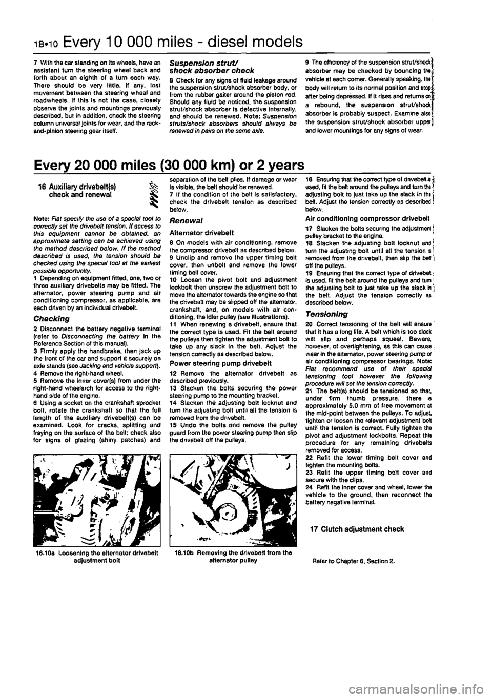
Note: Fiat specify the use of a spec/a/ toot to correctly set the drivebelt fens/on. if access to this equipment cannot be obtained, an approximate setting can be achieved using the method described beiow. If the method described Is used, the tension should be checked using the spec/a/ too! at the earliest possible opportunity. 1 Depending on equipment fitted, one, two or three auxiliary drivebeits may be fitted. The alternator, power steering pump and air conditioning compressor, as applicable, are each driven by an individual drivebelt. Checking 2 Disconnect the battery negative terminal (refer to Disconnecting the battery In the Reference Section of this manual). 3 Firmly apply the handbrake, then Jack up the Iront of the car and support it securely on exie stands (see Jacking and vehicle support). 4 Remove the right-hand wheel. 5 Remove the Inner cover(s) from under the right-hand wheelarch for access to the right-hand side of the engine. 6 Using a socket on the crankshaft sprocket bolt, rotate the crankshaft so that the full length of the auxiliary drivebelt(s) can be examined. Look for cracks, splitting and fraying on the surface of the belt: check also for signs of glazing (shiny patches) and
16.10a Loosening the alternator drivebelt adjustment bolt
separation of the belt plies. If damage or wear Is visible, the bell should be renewed, 7 If the condition of the belt Is satisfactory, check tho drivebelt tension as described below.
Renewal
Alternator drivebelt 8 On models with air conditioning, remove the compressor drivebelt as described below, 9 Unclip and remove the upper timing belt cover, then unbolt end remove the lower timing belt cover. 10 Loosen the pivot bolt and adjustment lockbolt then unscrew the adjustment bolt to move the alternator towards the engine so that the drivebelt may be slipped off the alternator, crankshaft, and, on models with air con-ditioning, the Idler pulley (see Illustrations), 11 When renewing a drivebelt. ensure that the correct type is used. Fit the belt around the pulleys then tighten the adjustment bolt to take up any slsck In the belt. Adjust the tension correctly as described below. Power steering pump drivebelt
12 Remove the alternator drivebelt as described previously. 13 Slacken the bolts securing the power steering pump to the mounting bracket. 14 Slacken the adjusting bolt locknut and turn the adjusting bolt until ail the tension Is removed from the dnvebelt. 15 Undo the bolts and remove the pulley guard from the power steering pump then slip the drivebelt off the pulleys,
16.10b Removing the drivebelt from the alternator pulley
18 Ensuring that the correct type of dnveberti^ used, fit the belt around the pulleys and turn
the
adjusting bolt to just take up the slack in thi j belt. Adjust the tension correctly as described! below. Air conditioning compressor drivebelt 17 Slacken the bolts securing the adjustment j pulley bracket to the engine. 18 Slacken the adjusting bolt locknut and] turn the adjusting bolt until ell the tension is | removed from the drivebelt. then slip the be& | off the pulleys. 19 Ensuring that the correct type of drivebeX; is used, fit ihe belt around the pulleys and turn | the adjusting bolt to just take up the slack
m
] the belt. Adjust the tension correctly as described below.
Tensioning 20 Correct tensioning of the belt will ensure that it has a long life. A belt which is too slack will slip and perhaps squeal. Beware, however, of overiightenlng. as this can cause wear in the alternator, power steering pump or air conditioning compressor bearings. Note: Flat recommend use of their spec's/ tensioning tool however the following procedure will set the tension correctly. 21 The belt(s) should be tensioned so that, under firm thumb pressure, there is approximately 5.0 mm of free movement at the mid-point between the pulleys. To adjust, tighten or loosen the relevant adjustment bolt until the tension is correct. Fully tighten the pivot and adjustment lockbotts. Repeat this procedure for any remaining drivebeits removed for access. 22 Refit the lower timing belt cover end tighten the mounting bolts. 23 Refit the upper timing belt cover and secure with the clips. 24 Refit the inner cover and wheel, lower the vehicle to the ground, then reconnect the battery negative terminal.
17 Clutch adjustment check
Refer lo Chapter 6, Section 2.
Page 75 of 225
Diesel engine in-car repair procedures
2C*11
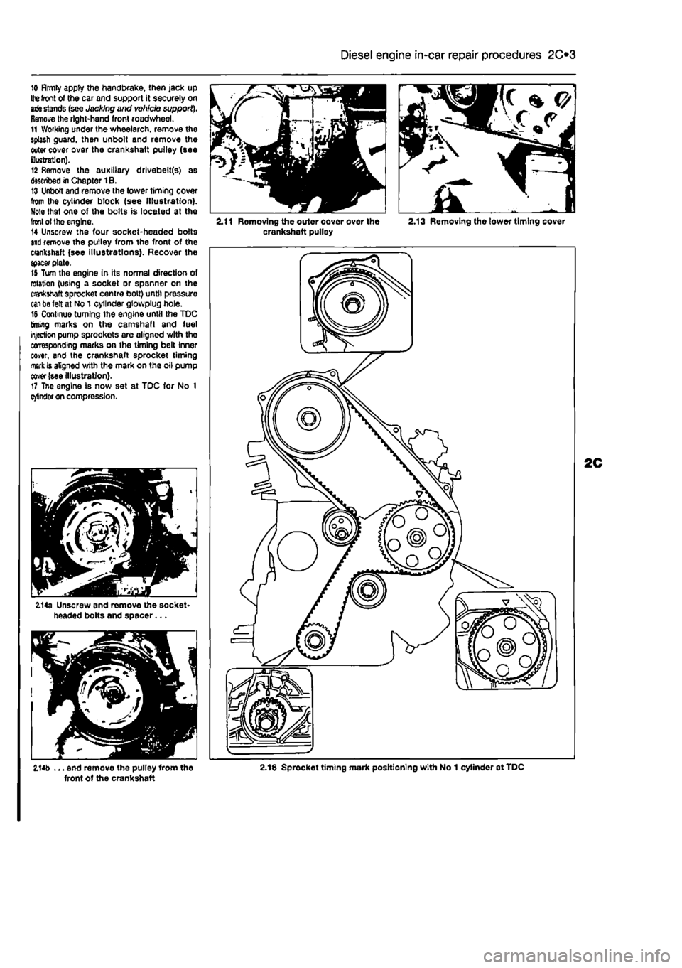
10 firmly apply the handbrake, then jack up
Ihe
front of the car and support it securely on
arte stands
(see Jacking and vehicle support). Remove the right-hand front roadwheel. 11 Working under the wheelarch. remove the splash guard, than unbolt and remove the outer cover over the crankshaft pulley (see ilustratlon). 12 Remove the auxiliary drivebelt(s) as described in Chapter 18. 13 Unbolt and remove the lower timing cover from the cylinder block (see Illustration). Note that one of the bolts is located at the
Iron!
of the engine. 14 Unscrew the four socket-headed bolts
and
remove the pulley from the front of the crankshaft (see illustrations). Recover the {pacer plate. 15 Turn the engine in its normal direction of rotation (using a socket or spanner on the crankshaft sprocket centre bolt) until pressure
can be
felt at No 1 cylinder gtowplug hole. 16 Continue turning the engine until the TDC timing marks on the camshaft and fuel injection pump sprockets are aligned with the corresponding marks on the timing belt inner cover, and the crankshaft sprocket timing
mark
is aligned with the mark on the oil pump cover (see illustration). 17 Tne engine is now set at TDC tor No 1 e>llnder on compression.
114a Unscrew and remove the socket-headed bolts and spacer...
2.11 Removing the outer cover over the 2.13 Removing the lower timing cover crankshaft pulley
2.14b ... and remove the pulley from the 2.18 Sprocket timing mark positioning with No 1 cylinder et TDC front of the crankshaft
Page 100 of 225
2D*10 Engine removal and overhaul procedures
V.
^
•
• - >v
4L
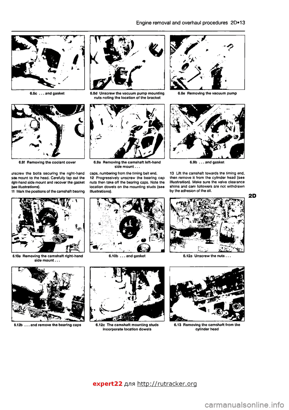
6.8c ... and gasket
unscrew the bolts securing the right-hand Side mount to the head. Carefully tap out the right-hand side mount and recover the gasket (see illustrations). 11 Mark the positions of the camshaft bearing
6.10a Removing tho camshaft right-hand side mount...
6.12b ... and remove the bearing caps
6.8d Unscrew the vacuum pump mounting nuts noting the location of the bracket
caps, numbering from the timing belt end. 12 Progressively unscrew the bearing cap nuts then take off the bearing caps. Note the location dowels on the mounting studs (sae Illustrations).
6.12c The camshaft mounting studs incorporate location dowels
6.8e Removing the vacuum pump
13 Lift the camshaft towards the timing end. then remove it from the cylinder head (see illustration). Make sure the valve clearance shims and cam followers are not withdrawn by the adhesion of the oil.
6.13 Removing the camshaft from the cylinder head
expert22 fl/in http://rutracker.org