tow FIAT PUNTO 1999 176 / 1.G User Guide
[x] Cancel search | Manufacturer: FIAT, Model Year: 1999, Model line: PUNTO, Model: FIAT PUNTO 1999 176 / 1.GPages: 225, PDF Size: 18.54 MB
Page 105 of 225
2D*10 Engine removal and overhaul procedures
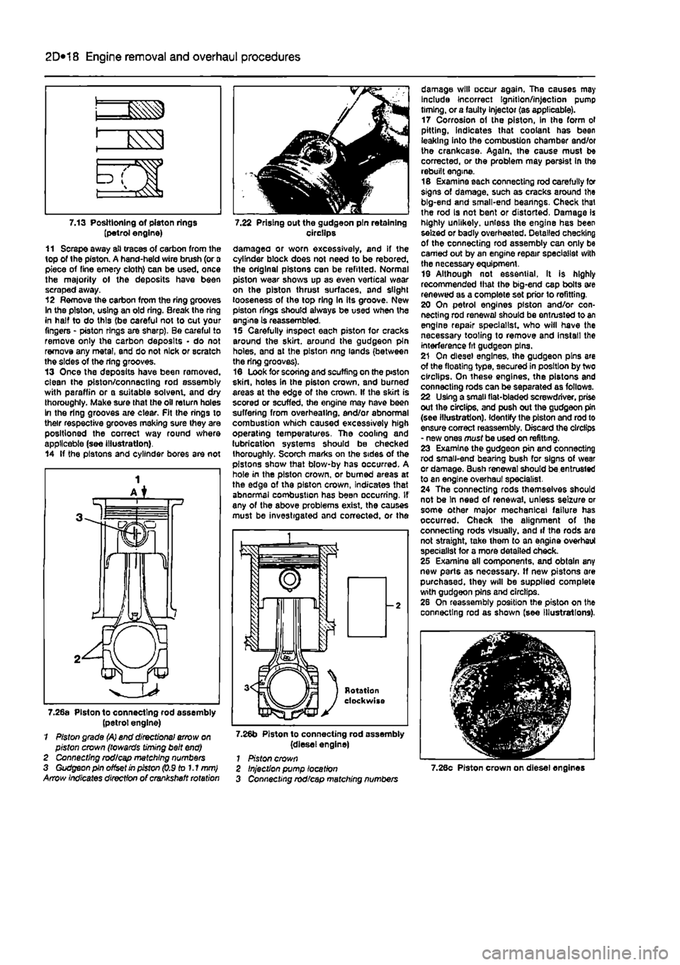
7.13 Positioning of piston rings (petrol engine) 11 Scrape away all traces of carbon from the top of the piston. A hand-held wire brush (or a piece of fine emery cloth) can be used, once the majority ot the deposits have been scraped away. 12 Remove the carbon from the ring grooves In the piston, using an old ring. Break the ring in half to do this (be careful not to cut your fingers - piston rings are sharp). Be careful to remove only the carbon deposits • do not remove any metal, end do not nick or scratch the sides of the ring grooves. 13 Once the deposits have been removed, clean the piston/connecting rod assembly with paraffin or o suitable solvent, and dry thoroughly. Make sure that the oil return holes In the ring grooves are clear. Fit the rings to their respective grooves meking sure they are positioned the correct way round where applicable (see illustration). 14 If the pistons and cylinder bores are not
7.22 Prising out the gudgeon pin retaining circilps damagea or worn excessively, and if the cylinder block does not need to be rebored. the original pistons can be refitted. Normal piston wear shows up as even vertical wear on the piston thrust surfaces, and slight looseness of the top ring In its groove. New piston rings should always be used when the engine is reassembled. 15 Carefully inspect each piston for cracks around the skirt, around the gudgeon pin holes, and at the piston nng lands (between the ring grooves). 16 Look for scoring and scuffing on the ptston skirt, holes in the piston crown, and burned areas at the edge of the crown. If the skirt is scored or scuffed, the engine may have been suffering from overheating, end/or abnormal combustion which caused excessively high operating temperatures. The cooling and lubrication systems should be checked thoroughly. Scorch marks on the sides of the pistons show that blow-by has occurred. A hole in the piston crown, or burned areas at the edge of the piston crown, Indicates that abnormal combustion has been occurring. If any of the above problems exist, the causes must be investigated and corrected, or the
7.26a Piston to connecting rod assembly (petrol engine) 1 Piston grade (A) end directional arrow on piston crown (towards timing belt end) 2 Connecting rod/cap matching numbers 3 Gudgeon pin offset in piston (0.9 to 1.1 mm) Arrow indicates direction of crankshaft rotation
7.26b Piston to connecting rod assembly (diesel engine) 1 Piston crown
damage will occur again. The causes may Include Incorrect Ignition/injection pump timing, or a faulty injector (as applicable). 17 Corrosion of the piston, in the form ol pitting, indicates that coolant has been leaking into the combustion chamber and/or the crankcase. Again, the cause must be corrected, or the problem may persist In the rebuilt engine. 16 Examine each connecting rod carefully for signs of damage, such as cracks around the big-end and small-end bearings. Check that the rod is not bent or distorted, Damage is highly unlikely, unless the engine has been seized or badly overheated. Detailed checking of the connecting rod assembly can only be earned out by an engine repair specialist with the necessary equipment. 19 Although not essential. It is highly recommended that the big-end cap bolts are renewed as a complete set prior lo refitting. 20 On petrol engines piston and/or con-necting rod renewal should be entrusted to an engine repair specialist, who will have the necessary tooling to remove and install the interference fit gudgeon pins. 21 On diesel engines, the gudgeon pins are of the floating type, secured in position by two circlips. On these engines, the pistons and connecting rods can be separated as follows. 22 Using a small fiat-bladed screwdriver, prise out ihe circlips, and push out the gudgeon pin (see illustration). Identify the piston and rod to ensure correct reassembly. Discard the circlips - new ones must be used on refitting. 23 Examine the gudgeon pin and connecting rod small-end bearing bush for signs of wear or damage. Bush renewal should be entrusted to an engine overhaul specialist. 24 The connecting rods themselves should not be In need of renewal, unless seizure or some other major mechanical failure has occurred. Check the alignment of the connecting rods visually, and if the rods are not straight, take ihem to an engine overhaul specialist for a more detailed check. 25 Examine all components, and obtain any new parts as necessary. If new pistons are purchased, they will be supplied complete with gudgeon pins and circlips. 26 On reassembly position the piston on the connecting rod as shown (see Illustrations),
Injection pump location Connecting rod/cap matching numbers 7.28c Piston crown on diesel engines
Page 106 of 225
Apply a smear of clean engine oil to the gudgeon pin. Slide it Into the piston and through the connecting rod small-end. Check that the piston pivots freely on the rod. then secure the gudgeon pin in position with two new circlips. Ensure that each circlip is correctly located In Its groove in the piston.
Refitting and big-end bearing running ciearance check 27 Prior to refitting the piston/connecting rod assemblies, it Is recommended that the big-end bearing running clearance is checked as follows. Big-end bearing running clearance check 28 Clean the backs of the bearing shells, and the bearing locations in both the connecting rod and bearing cap. 29 Press the bearing shells into their locations, ensuring that the tab on each shell engages in the notch In the connecting rod and cap. Take care not to touch any shell's bearing surface with your fingers. If the onginal bearing shells are being used for the check, ensure that they are refitted in their original locations. The clearance can be checked in either of two ways. 30 One method is to refit the big-end bearing cap to Ihe connecting rod, ensuring that they are litted the correct way around, with the bearing shells in place. Wilh the cap retaining bolls correctly tightened, use an internal micrometer or vernier caliper to measure the internal diameter of each assembled pair of bearing shells. If the diameter of each corresponding crankshaft journal is measured and Ihen subtracted from the bearing internal diameter, the result will be the big-end beanng running clearance. 31 The second, and more accurate method is to use a product called Plasligauge. Ensure that the bearing shells are correctly fitted then place a strand of Plastlgauge on each (cleaned) crankpin journal. 32 Refit the (clean) piston/connecting rod assemblies to the crankshaft, and refit the bg-end bearing caps, using the marks made or noted on removal to ensure that they are fitted the correct way around. 33 Tighten the beanng cap bolts taking care not to disturb the Plastlgauge or rotate the connecting rod dunng the tightening sequence. 34 Dismantle the assemblies without rotating the connecting rods. Use the scale pnnted on the Plastigauge envelope to obtain the big-end bearing running clearance. 35 If the clearance is significantly different from that expected, the bearing shells may be Ihe wrong size (or excessively worn. If the original shells are being re-used). Make sure mat no dirt or oil was trapped between Ihe bearing shells and the caps or block when the clearance was measured. If the Plastigauge was wider al one end than at the other, the crankshaft journal may be tapered.
2D*10 Engine removal and overhaul procedures
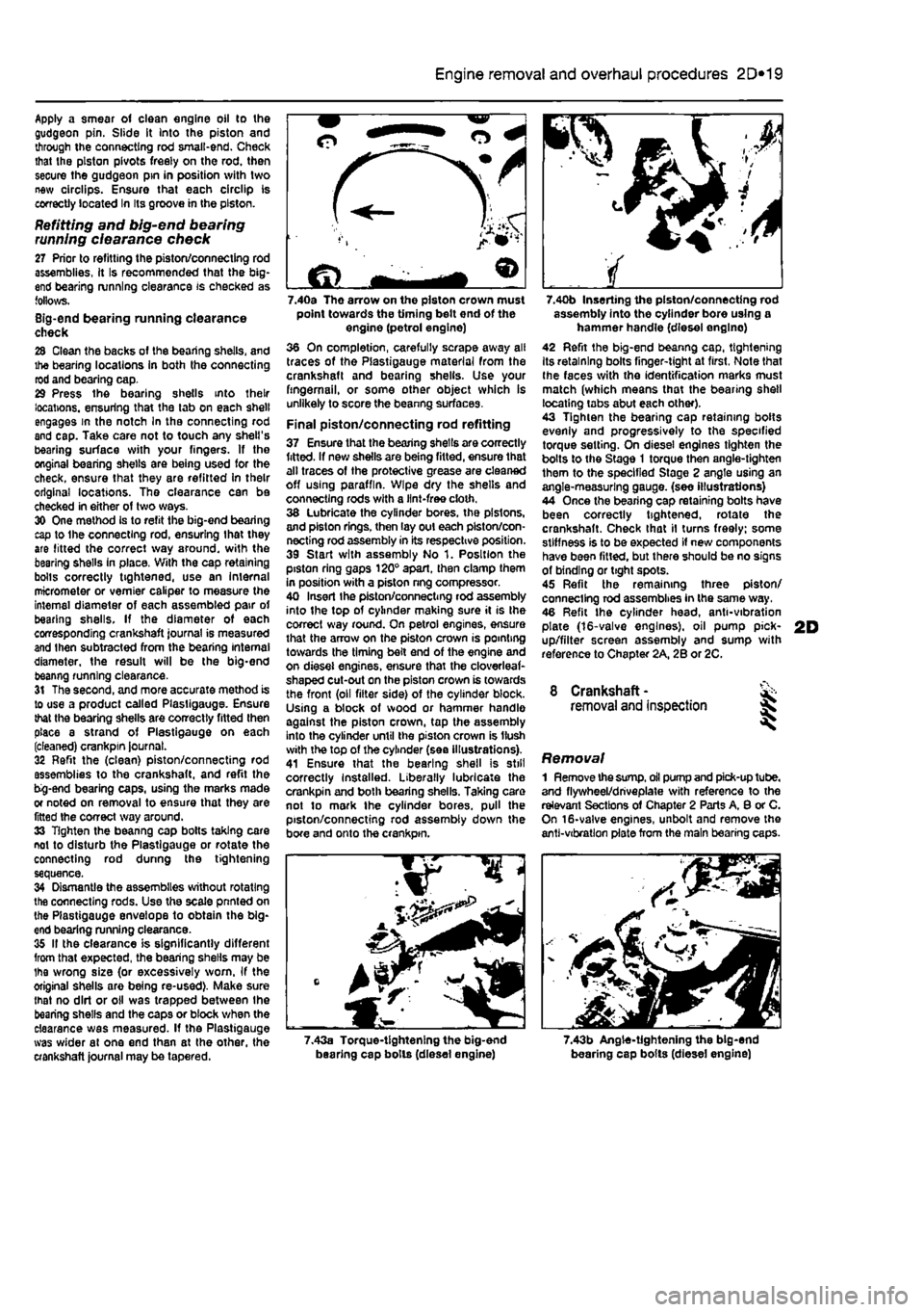
7.40a The arrow on the piston crown must point towards the timing belt end of the engine (petrol engine) 36 On completion, carefully scrape away all traces of the Plastigauge material from the crankshaft and bearing shells. Use your fingernail, or some other object which is unlikely to score the beanng surfaces.
Final piston/connecting rod refitting 37 Ensure that the bearing shells are correctly fitted. If new shells are being fitted, ensure that alt traces of the protective grease are cleaned off using paraffin. Wipe dry the shells and connecting rods with a lint-free cloth. 38 Lubricate the cylinder bores, the pistons, and piston rings, then lay out each piston/con-necting rod assembly in its respective position. 39 Start with assembly No 1. Position the piston ring gaps 120° apart, then clamp them in position with a piston nng compressor. 40 Insert Ihe piston/connecting rod assembly into the top of cylinder making sure it is Ihe correct way round. On petrol engines, ensure that the arrow on the piston crown is pointing towards the timing belt end of the engine and on diesel engines, ensure that the cloverleaf-shaped cut-out on the piston crown is towards the front (oil filter side) of the cylinder block. Using a block of wood or hammer handle against the piston crown, tap the assembly into the cylinder until the piston crown is Hush with the top of the cylinder (sea illustrations). 41 Ensure that the bearing shell is still correctly Installed. Liberally lubricate the crankpin and both bearing shells. Taking care not to mark the cylinder bores, pull the piston/connecting rod assembly down the bore and onto the crankpin.
7.40b Inserting the piston/connecting rod assembly into the cylinder bore using a hammer handle (diesel englno) 42 Refit the big-end beanng cap, tightening Its retaining bolts finger-tight at first, Note that Ihe faces with the identification marks must match (which means that the bearing shell locating tabs abut each other). 43 Tighten the bearing cap retaining bolts evenly and progressively to the specified torque setting. On diesel engines tighten the bolts to the Stage 1 torque then angle-tighten them to the specified Stage 2 angle using an angle-measuring gauge, (see illustrations) 44 Once the bearing cap retaining bolts have been correctly tightened, rotate the crankshaft. Check that il turns freely; some stiffness is to be expected if new components have been fitted, but there should be no signs of binding or tight spots. 45 Refit the remaining three piston/ connecting rod assemblies in the same way. 46 Refit the cylinder head, anti-vibration plate (16-valve engines), oil pump pick-up/filter screen assembly and sump with reference to Chapter 2A, 2B or 2C.
8 Crankshaft -removal and inspection 35
Removal 1 Remove the
sump,
oil pump and pick-up tube, and flywheel/driveplate with reference to the relevant Sections of Chapter 2 Parts A, 8 or C. On 16-valve engines, unbolt and remove the anti-vibration plate from the main bearing caps.
7.43a Torque-tightening the big-end bearing cap bolls (diesel engine) 7.43b Angle-tightening the big-end bearing cap bolts (diesel engine)
Page 107 of 225
2D*10 Engine removal and overhaul procedures
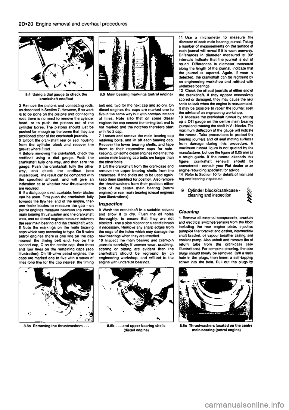
8.4 Using a dial gauge to check the crankshaft endfloat 2 Remove the pistons and connecting rods, as described in Section 7. However, If no work fs to be done on the pistons and connecting rods there is no need to remove the cylinder head, or to push the pistons out of the cylinder bores. The pistons should just be pushed far enough up the bores that they are positioned clear of the crankshaft Journals. 3 Unbolt the crankshaft rear oil seal housing from the cylinder block and recover the gasket where fitted. 4 Before removing the crankshaft, check the endfloat using a dial gauge. Push the crankshaft fully one way, and then zero Ihe gauge. Push the crankshaft fully the other way, and check tho endfloat (see Illustration). The result can be compared with the specified amount, and will give an indication as to whether new thrustwashers are required. 6 If a dial gauge is not available, feeler blades can be used. First push the crankshaft fully towards the flywheel end of the engine, then use feeler blades to measure the gap - on petrol engines measure between the centre main bearing thrust washer and the crankshaft web. and on diesel engines measure between the rear main bearing and tha crankshaft web. 6 Note the markings on the main bearing caps which vary according to type. On 8-valve petrol engines there is one line on Ihe cap nearest the timing belt end, two on the second cap, C on the centre cap, then three and four lines on the remaining caps (soo illustration). On 16-valve petrol engines, the caps are marked one to five with a series of lines (one line for the cap nearest the timing
8.6 Main bearing markings (petrol engine)
belt end, two for tho next cap and so on). On diesel engines the caps are marked one to live In the same way but with notches instead ol lines. Note also that on some diesel engines the cap nearest the timing belt end Is not marked and the notches therefore start with No 2 cap. 7 Loosen and remove the main bearing cop retaining bolts, and lift off each bearing cap. Recover the lower bearing shells, and tape them to their respective caps for safe-keeping. On some diesel engines note that the centre main bearing cap botts are longer than the other bolls. 8 Lift the crankshaft Irom the crankcase and remove the upper bearing shells from the crankcase. If the shells are 1o be used again, keep them identified for position. Also remove the thrustwashers from their position either side of the centre main bearing (petrol engines) or rear main bearing (diesel engines) (see illustrations)
Inspection 9 Wash the crankshaft in a suitable solvent and allow It to dry. Flush the oil holes thoroughly, to ensure that ihey are not blocked - use a pipe cleaner or a needle brush il necessary. Remove any sharp edges from the edge of the holes which may damage the new bearings when they are installed. 10 Inspect the main searing and crankpin journals carefully; if uneven wear, cracking, scoring or pitting are evident then the crankshaft should be reground by an engineering workshop, and refitted to the engine with underslze bearings.
11 Use a micrometer to measure the diameter of each main bearing journal. Taking a number of measurements on the surface of each journal will reveal if it Is worn unevenly. Differences in diameter measured at 90" intervals Indicate that the journal is out of round. Differences In diameter measured aiong the length of the journal, indicate that the journal is tapered. Again. If wear is detected, the crankshaft can be reground by an engineering workshop and refitted with undersize bearings. 12 Check the oil seal journals at either end of the crankshaft. If they appear excessively scored or damaged, they may cause the new seals to leak when the engine is reassembled. It may be possible to repair the |ournal; seek the advice of an engmeenng workshop. 13 Measure the crankshaft runoul by setting up a DTI gauge on the centre main bearing journal and rotating the shaft In V - blocks. The maximum deflection of the gauge will indicate Ihe runout. Take precautions to protect the bearing journals and oil seal mating surfaces from damage during this procedure. A maximum runout figure Is not quoted by the manufacturer, but use the figure of 0.05 mm
a»
a rough guido. If the runoul exceeds this figure, crankshaft renewal should be considered • consult your Flat dealer or an engine rebuilding specialist for advico. 14 Refer to Section 10 for details of main and big-end bearing inspection.
9 Cylinder block/crankcase - % cleaning and inspection Sk
Cleaning 1 Remove all external components, brackets and electrical switches/sensors from the block Including the rear engine plate, injection pump/oil filter bracket and gasket, Intermediate shaft bracket, oH vapour breather casing, and coolant pump. Also unboit and remove the ol return tube from the crankcase (see illustrations). For complete cleaning, the core plugs should Ideally be removed. Drill a small hole in the plugs, then insert a self-tapping screw into the hole. Pull out the plugs by
8.8a Removing the thrustwashers.. ... and upper bearing shells (diesel engine) 8.8o Thrustwashers located on the centre main bearing (petrol engine)
Page 115 of 225
3*2 Cooling, heating and ventilation systems
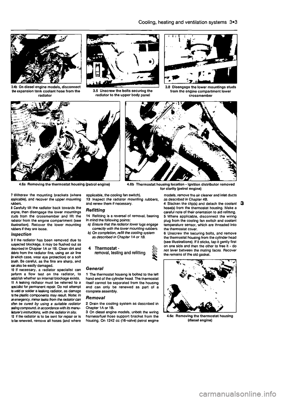
3.4b On diesel engine models, disconnect the expansion tank coolant hose from the radiator 3.5 Unscrew the bolts securing the radiator to the uppor body panel
3.8 Disengage the lower mountings studs from the onglne compartment lower crossmember
4.6a Removing the thermostat housing (petrol engine) 4.6b Thermostat housing location - Ignition distributor removed for clarity (petrol engine) ? Withdraw the mounting brackets (where applicable), and recover the upper mounting rubbers. 8 Carefully tilt the radiator back towards the engine, then disengage the lower mountings studs from the crossmember and lift the radiator from the engine compartment (see illustration). Recover the lower mounting rubbers if they are loose. Inspect/on 9II the radiator has been removed due to suspected blockage, it may be flushed out as descnbed in Chapter lAor 10. Clean dirt and debris from the radiator fins, using an air line fn which case, wear eye protection) or a soft Brush. Be careful, as the fins are sharp, and
can
also be easily damaged. ID If necessary, a radiator specialist can perform a flow test on the radiator, to establish whether an internal blockage exists. 11 A leaking radiator must be referred to a specialist for permanent repair. Do not attempt to weld or solder a leaking radiator, as damage to the plastic components may result. Note: In
an emergency,
minor
leaks
from the radiator can often be cured by using a suitable radiator seat'ng compound, in accordance with its manu-
facturer's
instructions, with the radiator in situ. 12 If the radiator is to be sent for repair or is
to
be renewed, remove all hoses (and where
applicable, the cooling fan switch). 13 Inspect Ihe radiator mounting rubbers, and renew them if necessary. Refitting 14 Refitting is a reversal of removal, bearing in mind the following points: a) Ensure that the radiator lower lugs engage correctly with the lower mounting rubbers. b) On completion, refill the cooling system as described in Chapter 1A or IB.
Thermostat - Jk removal, testing and refitting #
General 1 The thermostat housing Is bolted to the left hand end of the cylinder head. The thermostat itself cannot be separated from the housing and can only be renewed as part of a complete assembly.
Removal 2 Drain the cooling system as described in Chapter 1A or 1B. 3 On diesel engine models, unbolt the wiring harness/fuel hose support bracket from the housing. On 1242 cc (16-valve) petrol engine
models, remove the air cleaner and inlet ducts as descnbed in Chapter 4B. 4 Slacken the clipfs) and detach the coolant hose(s) from the thermostai housing, Make a careful note of their orientation to aid refitting. 5 Where applicable, disconnect the wiring plug from the cooling fan switch and coolant temperature sensor, which are threaded into the thermostat cover. 6 Unscrew the securing bolts, and remove the thermostat housing from the cylinder head (see illustrations). If it sticks, tap it gently first on one side and then the other to free it - do not lever between the mating faces. Recover the remains of the old c,
4.6c Removing the thermostat housing (diesel engine)
Page 140 of 225
Fuel system - diesel models
4C*3
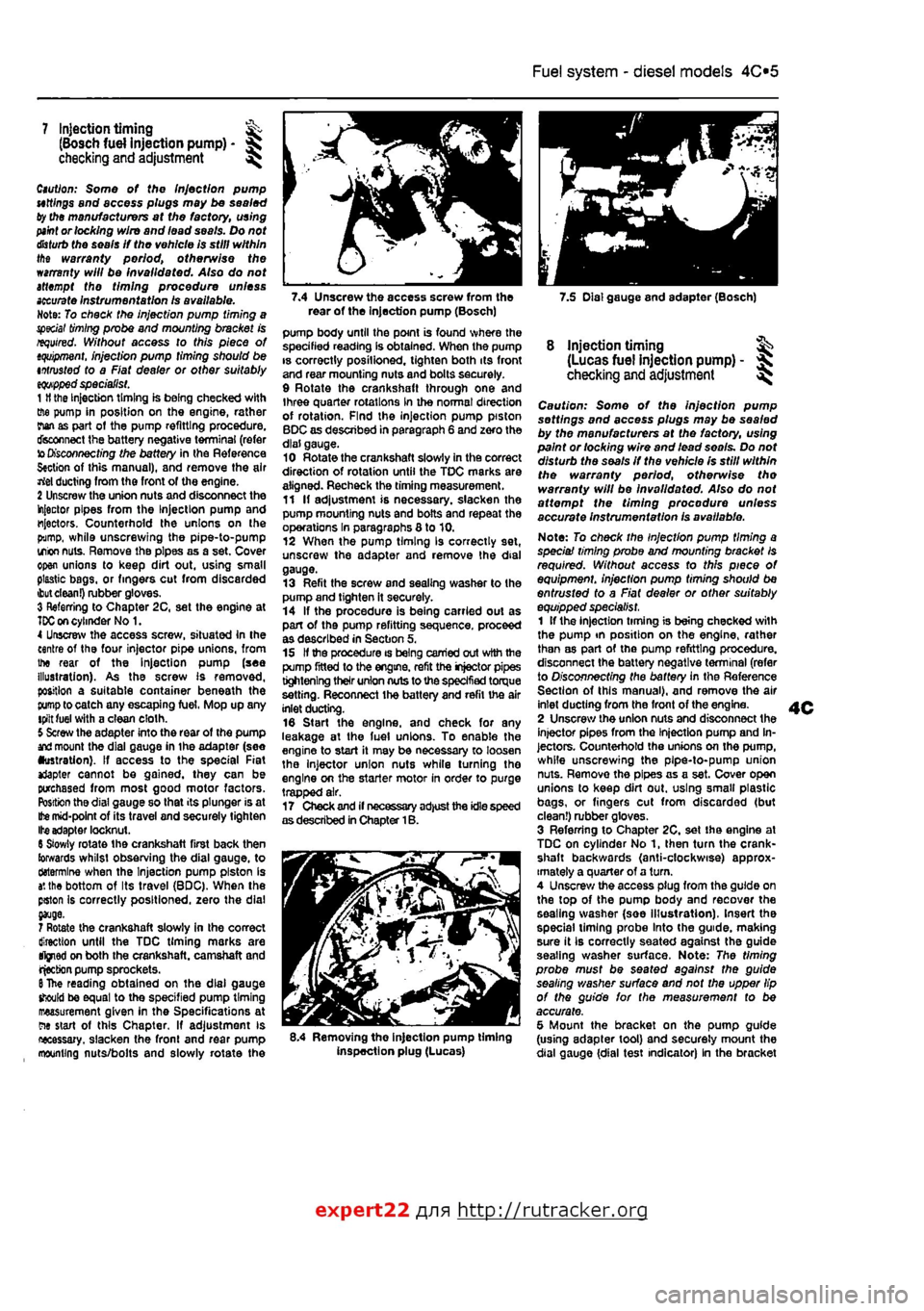
7.4 Unscrew the access screw from the 7.5 Dial gauge and adapter (Bosch) rear of the Injection pump (Bosch)
7 Injection timing ^ (Bosch fuel injection pump) -checking and adjustment ^
Caution: Some of the Injection pump uttlngs and access plugs may be sealed ty the manufacturers at the factory, using
paint
or locking wire and lead seals. Do not
disturb
the seals If the vehicle is still within the warranty period, otherwise the warranty will be invalidated. Also do not attempt the timing procedure unless
accurate
Instrumentation Is available. Note: To check the injection pump timing a special
timing
probe and mounting bracket is required. Without access to this piece of
tquipment.
injection pump timing should be intrusted to a Fiat dealer or other suitably
eqwpped
specialist. 1
H
the Injection timing is being checked with ffie pump in position on the engine, rather rian as part ot the pump refitting procedure, disconnect the battery negative terminal (refer to
Disconnecting
the battery in the Reference S«ction of this manual), and remove the air rtel ducting from the front of the engine. 2 Unscrew the union nuts and disconnect the injector pipes from the Injection pump and injectors. Counterhold the unions on the pump, while unscrewing the pipe-to-pump irion
nuts.
Remove the pipes as a set. Cover open unions to keep dirt out, using small plastic bags, or fingers cut from discarded
ibut clean!)
rubber gloves. 3 Referring to Chapter 2C, set the engine at
TDC on
cylinder No 1. 4 Unscrew the access screw, situated In the centre of the four injector pipe unions, from the rear of the Injection pump (see illustration). As the screw Is removed, position a suitable container beneath the
pump
to catch any escaping fuel, Mop up any tpilt fuel with a clean cloth. 5 Screw the adapter into the rear of the pump
and
mount the dial gauge in ihe adapter (see •ustration). If access to the special Fiat *Japter cannot be gained, they can be purchased from most good motor factors. Position the dial gauge so that its plunger is at
Ifce
mid-point of its travel and securely tighten Ite adapter locknut. 6 Slowly rotate the crankshaft first back then towards whilst observing the dial gauge, to ctotermlne when the Injection pump piston is
a',
the bottom of Its travel (BDC), When the pston Is correctly positioned, zero the dial
7 Rotate the crankshaft slowly in the correct direction until the TDC timing marks are tfjned on both the crankshaft, camshaft and rjecbon pump sprockets.
6
The reading obtained on the dial gauge should be equal to the specified pump timing measurement given in the Specifications at ew start of this Chapter, If adjustment is necessary, slacken the fronl and rear pump mounting nuts/bolts and slowly rotate the
pump body until the point is found where the specified reading Is obtained. When the pump is correctly posilioned, tighten both its front and rear mounting nuts and bolts securely. 9 Rotate the crankshaft through one and three quarter rotations in the normal direction of rotation. Find the injection pump piston BDC as described in paragraph 6 and zero the dial gauge. 10 Rotate the crankshaft slowly in the correct direction of rotation until the TDC marks are aligned. Recheck the timing measurement. 11 If adjustment is necessary, slacken the pump mounting nuts and bolts and repeat the operations In paragraphs 8 to 10. 12 When the pump timing Is correctly set, unscrew the adapter and remove the dial gauge. 13 Refit the screw and sealing washer to the pump and tighten it securely. 14 If the procedure is being carried out as part of the pump refitting sequence, proceed as described in Section 5, 15 If the procedure is being carried out with the pump fitted to the engine, refit the injector pipes tightening their union nuts to the specified torque setting. Reconnect the battery and refit the air inlet ducting. 16 Start the engine, and check for any leakage at the luel unions. To enable the engine to start it may be necessary to loosen the injector union nuts while turning tho engine on the starter motor in order to purge trapped air. 17 Check and if necessary adjust the idle speed as described in Chapter 1B.
8.4 Removing the injection pump timing inspection plug (Lucas)
8 injection timing ^ (Lucas fuel injection pump) - ^ checking
and
adjustment ^
Caution: Some of the injection pump settings and access plugs may be sealed by the manufacturers at the factory, using paint or locking wire and lead seo/s. Do not disturb the seals if the vehicle Is still within the warranty period, otherwise tho warranty will be Invalidated. Also do not affempf the timing procedure unless accurate instrumentation is available.
Note: To check the Injection pump timing a speciai timing probe and mounting bracket Is required. Without access to this piece of equipment, injection pump timing should be entrusted to a Fiat dealer or other suitably equipped specialist. 1 If the injection timing is being checked with the pump tn position on the engine, rather than as part of the pump refitting procedure, disconnect the battery negative terminal (refer to Disconnecting the battery in the Reference Section of this manual), and remove the air inlet ducting from the front of the engine. 2 Unscrew the union nuts and disconnect the injector pipes from the Injection pump and In-jectors. Counterhold the unions on the pump, while unscrewing the pipe-to-pump union nuts. Remove the pipes as a set. Cover open unions to keep dirt out. using smalt plastic bags, or fingers cut from discarded (but clean!) rubber gloves. 3 Referring to Chapter 2C, set the engine at TDC on cylinder No 1, then turn the crank-shaft backwards (anti-clockwise) approx-imately a quarter of a turn. 4 Unscrew the access plug from the guide on the top of the pump body and recover the sealing washer (soe Illustration). Insert the special liming probe Into the guide, making sure it Ib correctly seated against the guide seating washer surface. Note: The timing probe must be seated against the guide sealing washer surface and not the upper lip of the guide for the measurement to be accurate. 5 Mount the bracket on the pump guide (using adapter tool) and securely mount the dial gauge {dial test indicator) In the bracket
expert22 fl/i* http://rutracker.org
Page 147 of 225
4D*4 Exhaust and emission control systems
d) DO NOT push- or tow-start the car - this will soak the catalytic converter
in
unbumed fuel, causing It to overheat when the engine does start. e) DO NOT switch off the ignition at high engine speeds. f) DO NOT use fuel or engine oil additives -these may contain substances harmful to the catalytic converter. g) DO NOT continue to use the car If
the
engine bums oil to the extent of leaving
a
visible trail of blue smoke.
h) Remember that the catalytic converter operates at very high temperatures. DO NOT, therefore, park the car in dry undergrowth, over long grass or piles of deed leaves after a long run. I) Remember that the catalytic converter is FRAGILE - do not strike it with tools during servicing work, j} In some cases a sulphurous smell
pike
that of rotten eggs) may be noticed from the exhaust. This Is common to many catalytic converter-equipped cars and
once the car has covered a few
thousand
miles tha problem should
disappear,
k)
The
catalytic converter, used on a
weW*
maintained and well-driven car, should las for between
SO
000 and
100
000
miles-If
the converter is no longer effective It
must
be renewed.
Diesel models Refer to the information given in parts i,
g, h
and I of the petrol models information given above.
Page 149 of 225
5A«2 Starting and charging systems
1 General information and precautions
General information The engine electrical system consists mainly of the charging and starting systems. Because of their engine-related functions, these components are covered separately from the body electrical devices such as the Ilght3, Instalments, etc (which are covered In Chapter 12). On petrol engine models refer to Part B for information on the ignition system, and on diesel models refer to Part C for information on the preheating system. The electncal system Is of 12-volt negative earth type. The battery fitted as original equipment is of maintenance* free (sealed for life} type and Is charged by the alternator, which is belt-driven from the crankshaft pulley. If a non-original battery is fitted It may be of standard or low maintenance type. The starter motor is of the pre-engaged type Incorporating an integral solenoid. On starting, the solenoid moves the drive pinion into engagement with the flywheel ring gear before the starter motor is energised. Once the engine has started, a one-way clutch prevents the motor armature being driven by the engine until the pinion disengages from the flywheel.
Precautions Further details of the various systems are given In the relevant Sections of this Chapter. While some repair procedures are given, the usual course of action is to renew the component concerned. The owner whose interest extends beyond mere component renewal should obtain a copy of the Automobile Electrical & Electronic Systems Manual, available from the publishers of this manual It Is necessary to take extra care when working on the electrical system to avoid damage to semiconductor devices (diodes and transistors), and to avoid the risk of personal injury. In addition to the precautions given in Safety first! at the beginning of this manual, observe the following when working on the system: Always remove rings, watches, etc before working on the electrical system. Even with the battery disconnected, capacitlve discharge could occur If a component's live terminal is earthed through a metal object. This could cause a shock or nasty bum. Do not reverse the battery connections. Components such as the alternator, electronic control units, or any other components having semi-conductor circuitry could be irreparably damaged. If the engine is being started using jump leads and a slave battery, connect the batteries positive-to-posibve and negative-to-
negative (see Jump starting). This also applies when connecting a battery charger but In this case both of the battery terminals should first be disconnected. Never disconnect the battery terminals, the alternator, any electrical wiring or any test Instalments when the engine Is running. Do not allow the engine to turn the alter-nator when the alternator Is not connected. Never test for alternator output by flashing the output lead to earth. Never use an ohmmeter ot the type Incorporating a hand-cranked generator for circuit or continuity testing. Always ensure that the battery negative lead is disconnected when working on the electrical system. Before using electric-arc welding equipment on the car, disconnect the battery, alternator and components such as the fuel Injection/ignition electronic control unit to protect them from the risk of damage. Several systems fitted to the vehicle require battery power to be available at all times, either to ensure their continued operation (such as the clock) or to maintain control unit memories or security codos which would be wiped if the battery were to be disconnected. To ensure that there are no unforeseen consequences of this action. Refer to Disconnecting the battery In the Reference Section of this manual for further Information.
2 Battery- % testing and charging
Standard and tow maintenance battery - testing 1 If the vehicle covers a small annual mileage, it is worthwhile checking the specific gravity of the electrolyte every three months to determine the state of charge of the battery. Use a hydrometer to make the check and compare the results with the following table, Note that the specific gravity readings assume an electrolyte temperature of 15*C (60'F); for every 10*C (18°f) below 158C (60aF) subtract 0.007, For every 108C (16'F) above 15"C (60'F) add 0.007. Ambient temperature Above 26"C Below 25DC Charged 1,210 to 1£30 1,270 to 1.290 70% charged 1.170to1.l90 1.230to1.250 Discharged 1.050toJ.070 1.110 to 1.130 2 If the battery condition is suspect, first check the specific gravity of electrolyte In each cell. A variation of 0.040 or more between any cells indicates loss of electrolyte or deterioration of the internal plates. 3 If the specific gravity variation is 0.040 or more, the battery should be renewed. If the cell variation Is satisfactory but the battery is discharged, it should be charged as described later in this Section.
Maintenance-free battery -testing 4 In cases where a sealed tor life maintenance-free battery is fitted, topplng-up and testing of the electrolyte in each cell Is not possible. The condition of the battery can therefore only be tested using a battery condition Indicator or a voltmeter. 5 Certain models may be fitted with a maintenance-free battery with a built-in charge condition Indicator. The indicator Is located in the top of the battery casing, and indicates the condition of the battery from its colour. If the Indicator shows green, then the battery is In a good state of charge. If the Indicator turns darker, eventually to black, then the battery requires charging, as described later in this Section. If Ihe indicator shows clear/yellow, then the electrolyte level in Ihe battery is too low to allow further use, and tho battery should be renewed. Do not attempt to charge, load or Jump start a battery when the indicator shows dear/yellow. 6 If testing the battery using a voltmeter, connect the voltmeter across the battery and compare the result with those given In the Specifications under 'charge condition'. The test is only accurate if the battery has not been subjected to any kind of charge for the previous six hours. If this is not the esse, switch on the headlights for 30 seconds, then wait four to five minutes baforo testing the battery after switching off the headlights. All other electrical circuits must be switched off, so check that the doors and tailgate are fully shut when making the test, 7 It the voltage reading Is less than 12.2 voHs, then the battery Is discharged, whilst a reading of 12.2 to 12.4 volts indicates 8 partially discharged condition. 6 If the battery Is to be charged, remove It from the vehicle (Section 3) and charge it as described later In this Section.
Standard and low maintenance battery - charging Note: The following is Intended as a guide only. Always refer to the manufacturer's recommendations (often printed on a label attached to the battery) before charging a battery. 9 Charge the battery at a rate of 3.5 to 4 amps and continue to charge the battery at this rate until no further rise In specific gravity Is noted over a four hour period. 10 Alternatively, a trickle charger charging at the rate of 1.5 amps can safely be used overnight. 11 Specially rapid boost charges which are claimed to restore the power of the battery in t to 2 hours are not recommended, as they can cause serious damage to the battery plates through overheating, 12 While charging the battery, note that the temperature of the electrolyte should never exceed 37.8*C(100°F),
Page 150 of 225
5A«2 Starting and charging systems
Maintenance-free battery -charging Note: The following is intended as a guide only. Always refer to the manufacturer's recommendations (often printed on a label attached to the battery) before charging a battery. 13 This battery type takes considerably longer lo fully recharge than the standard type, the time taken being dependent on the extent of discharge, but it can take anything
up
to three days. 14 A constant voltage type charger is required, tooe set, when connected, to 13.9 to 14.9 votts wth a charger current below 25 amps. Using
mis
method, the battery should be usable within three hours, giving a voltage reading of 12.5 vofts. but this Is for a partially discharged battery and, as mentioned, full charging can
take
considerably longer. 15 If Ihe battery is to be charged from a fully discharged state {condition reading loss lhan 12.2 volts), have it recharged by your FIAT dealer or local automotive electrician, as Ihe charge rate is higher and constant super-vision during charging Is necessary.
3 Battery -removal and refitting
Note: Refer to Disconnecting the battery in ifte Reference Section of this manual before proceeding.
Removal 1 Slacken the clamp bolts and disconnect the ctamp from the battery negative (earth) terminal. 2 Remove the insulation cover (where fitted)
and
disconnect the positive terminal lead(s) in
Die same
way. 3 At the base of the battery, unscrew the bolt from the battery holding clamp plate and remove the clamp plate (see Illustration). A Remove the battery from Ihe engine compartment. 5 II necessary the mounting tray may be removed by unscrewing the bolts. On diesel models it will be necessary to remove the relay guard bolts as well.
Refitting 6 Refitting is a reversal of removal but make sure that the positive terminal is connected first followed by the negative terminal.
4 Alternator/charging system - >%•> testing in vehicle
Note: Refer to the warnings given in Safety first! and in Section 1 of this Chapter before starting work. 1 If the ignition warning light fails to Illuminate when the ignition is switched on, first check the alternator wiring connections for security. If satisfactory, check that the warning light bulb has not blown, and that the bulbholder is secure in its location in the instrument panel. If the light still fails to illuminate, check the continuity of the warning light feed wire from the alternator to the bulbholder. If all is satisfactory, the alternator is at fault and should be renewed or taken to an auto-electrician for testing and repair. 2 If the ignition warning light Illuminates when the engine Is running, stop the engine and check that the drivebelt is correctly tensioned (see Chapter 1A or 18) and that the alternator connections are secure. If all is so far satisfactory, have the alternator checked by an auto-electrician. 3 If the alternator output is suspect even though the warning light functions correctly, the regulated voltage may be checked as follows. 4 Connect a voltmeter across the battery terminals and start the engine. 5 Increase the engine speed until the voltmeter reading remains steady; the reading should be approximately 12 to 13 volts, and no more than 14 volts. 6 Switch on as many electrical accessories (eg. the headlights, heated rear window and heater blower) as possible, and check that the alternator maintains the regulated voltage at around 13 to 14 volts. 7 If ihe regulated voltage is not as stated, the fault may be due to worn brushes, weak brush springs, e faulty voltage regulator, a faulty diode, a severed phase winding or worn or damaged slip rings. The alternator should be renewed or taken to an auto-electrician for testing and repair.
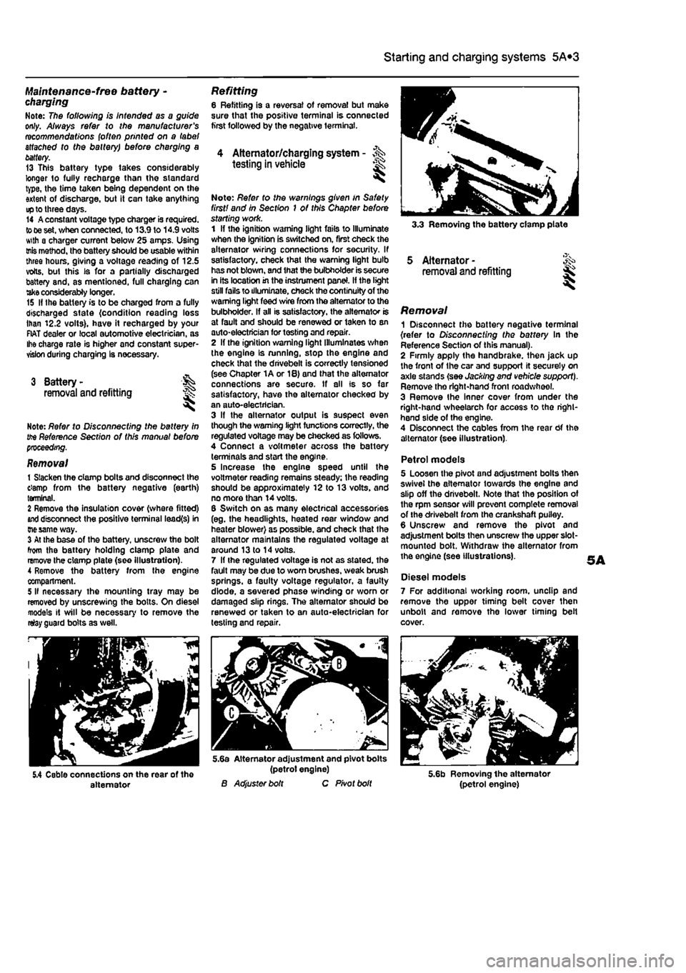
3.3 Removing the battery clamp plate
5 Alternator -removal and refitting
Removal 1 Disconnect the battery negative terminal {refer to Disconnecting the battery In the Reference Section of this manual). 2 Firmly apply the handbrake, then jack up the front of the car and support it securely on axle stands (see Jacking and vehicle support). Remove tho right-hand front roadwheel. 3 Remove Ihe Inner cover from under the right-hand wheelarch for access to tho right-hand side of the engine. 4 Disconnect the cables from the rear Of the alternator (see illustration).
Petrol models 5 Loosen the pivot and adjustment bolts then swivel the alternator towards the engine and slip off the drivebelt. Note that the position of the rpm sensor will prevent complete removal of the drivebelt from the crankshaft puiley. 6 Unscrew and remove the pivot and adjustment bolts then unscrew the upper slot-mounted bolt. Withdraw the alternator from the engine (see illustrations).
Diesel models 7 For additional working room, unclip and remove the upper timing belt cover then unbolt and remove the lower timing belt cover.
5.4 Cable connections on the rear of the alternator
5.6a Alternator adjustment and pivot bolts (petrol engine) B Adjuster bolt C Pivot bolt 5.6b Removing the alternator (petrol engine)
Page 151 of 225
5A«2 Starting and charging systems
5.9a Unbolting the alternator upper bracket from the rear of the coolant pump
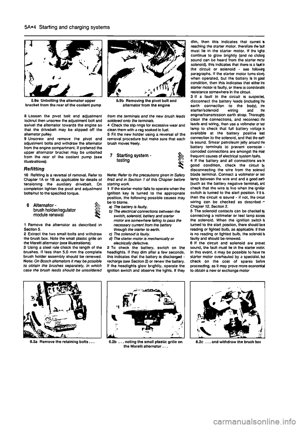
fl Loosen the pivot bolt and adjustment locknut then unscrew the adjustment bolt and swivel the alternator towards the engine so that the drivebefi may be slipped off the alternator pulley. 9 Unscrew and remove the pivot and adjustment bolts and withdraw the alternator Irom the engine compartment. If preferred the upper alternator bracket may bo unbolted from the rear of the coolant pump {see illustrations).
Refitting 10 Refitting is a reversal ot removal. Refer to Chapter tA or 1B as applicable for details of tensioning the auxiliary drivebeit. On completion lighten the pivot and adjustment botts/nut to the specified torque.
6 Alternator -brush holder/regulator module renewal
%
1 Remove the alternator as described in Section 5. 2 Extract the two small bolts and withdraw the brush box. Note the small plastic grille on the Marelli alternator (see illustrations), 3 Using a steol rule chock the length of the brushes. If less than 5.0 mm the complete brush holder assembly should be renewed. Note: On Bosch alternators it may be possible to obtain the brushes separate//, in which case the brush ieads should be unsoldered
5.9b Removing the pivot bolt and alternator from the engine
from ihe terminals and the new brush leads soldered onto the terminals. 4 Check the slip rings for excessive wear and clean them with a rag soaked in fuel. 5 Pit the new holder using a reversal of the removal procedure but make sure that each brush moves freely.
7 Starting system • & testing
Note: Refer to Ihe precautions given In Safety firstI and in Section I of this Chapter before stoning work. 1 If the starter motor falls to operate when the Ignition key Is turned to the appropriate position, the following possible causes may be to blame. aj The battery is faulty. b) The electrical connections between the switch, solenoid, battery and starter motor are somewhere failing to pass the necessary current from the battery through the starter to earth. c) 77:© solenoid is faulty. d) The starter motor is mechanically or electrically defective. 2 To check the battery, switch on the headlights. If they dim after a few seconds, this indicates that the battery is discharged -recharge (see Section 2) or renew the battery. If the headlights glow brightly, operate the ignition switch and observe the lights. If they
dim, then this indicates that current it reaching the starter motor, therefore the iao8 must lie In the starter motor. If the lights continue to glow brightly (and no clicking sound can be heard from the starter motor solenoid), this indicates that there is a lairt
In
the circuit or solenoid - see following paragraphs, if the starter motor turns siowfy when operated, but the battery is In good condition, then this indicates that either lae starter motor is faulty, or there is considers resistance somewhere in the circuit. 3 If a fault in the circuit is suspected, disconnect the battery ieads (including ihe earth connection to the body), lt» starter/solenoid wiring and tne engine/transmission earth strap. ThoroygWy clean the connections, and reconnect the leads and wiring, ihen use a voltmeter or J«i lamp to check that full battery voltage is available at the battery positive lead connection to the solenoid, and that the earth is sound. Smear petroleum jelly around ttie battory terminals to prevent corrosion > corroded connections are amongst the most frequent causes of electrical system faults. 4 If the battery and all connections are in good condition, check the circuit disconnecting the wire from the solenod blade terminal. Connect a voltmeter or less lamp between the wire end and a good earth (such as the battery negative terminal), ais check that the wire is live when tne ignition switch is turned to the start position. If It is. then the circuit is sound - if not. the circut wiring can be checked as described Chapter 12. Section 2. 5 The solenoid contacts can be checked
Oy
connecting a voltmeter or test lamp across Ihe solenoid. When the ignition switch is turned to the start position, there should b»a reading or lighted bulb, as applicable. II thars is no reading or lighted bulb, the solenoid is faulty and should be renewed. 6 If the circuit and solenoid are proves sound, the fault must lie in the starter motor. In this event, it may be possible to have tre starter motor overhauled by a specialist, but check on the cost of spares before proceeding, as It may prove more economical to obtain a new or exchange motor
Page 167 of 225
7B*2 Automatic transmission
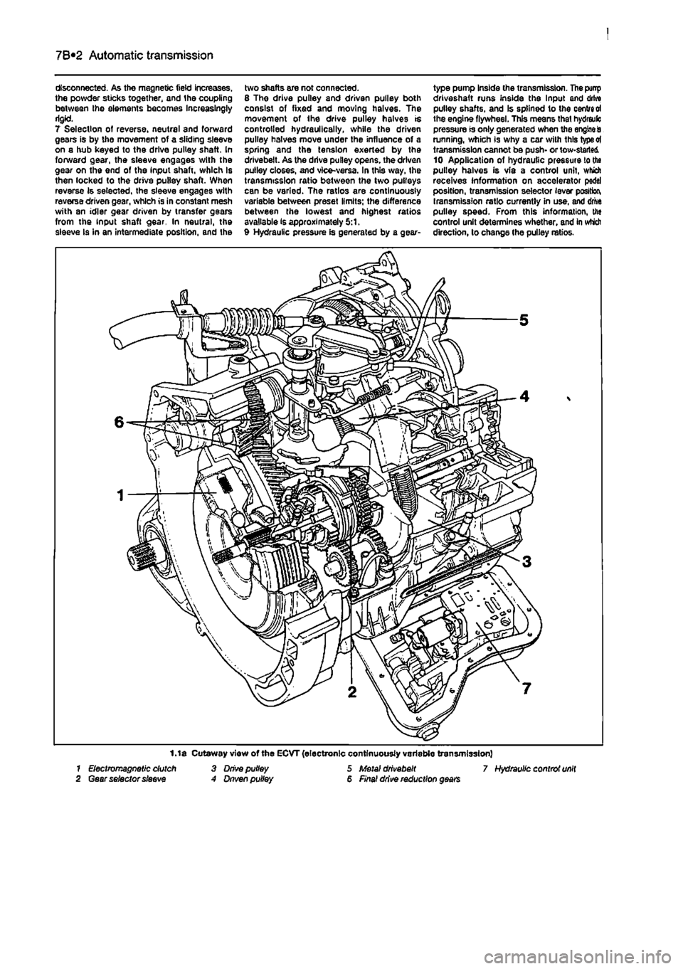
disconnected. As the magnetic field increases, the powder sticks together, and the coupling between Ihe elements becomes Increasingly rigid. 7 Selection of reverse, neutral and forward gears is by the movement of a sliding sleeve on a hub keyed to the drive pulley shaft. In forward gear, the sleeve engages with the gear on the end of the input shaft, which is then locked to the drive pulley shaft. When reverse is selected, the sleeve engages with reverse driven gear, which is in constant mesh with an idler gear driven by transfer gears from the input shaft gear. In neutral, the sleeve Is in an intermediate position, and the
two shafts are not connected. 8 Tho drive pulley and driven pulley both consist of fixed and moving halves. The movement of ihe drive pulley halves is controlled hydraulically, while the driven pulley halves move under the influence of a spring and the tension exerted by the drivebeit. As the drive pulley opens, the driven pulley closes, and vice-versa. In this way, the transmission ratio between the two pulleys can be varied. The ratios are continuously variable between preset limits; the difference between the lowest and highest ratios available is approximately 5:1. 9 Hydraulic pressure is generated by a gear-
type pump Inside the transmission. The punp driveshaft runs inside the Input and drive pulley shafts, and Is splined to the centred the engine flywheel. This means that hydreulc pressure is only generated when the engine is running, which is why a car with this type ot transmission cannot be push- or tow-started 10 Application of hydrautic pressure to the pulley halves is via a control unit, which receives information on accelerator pedal position, transmission selector lever position, transmission ratio currently in use, and drive pulley speed. From this information, the control unit determines whether, and in which direction, lo change the pulley ratios.
1.1 a Cutaway view of the ECVT (electronic continuously variable transmission) 7 Electromagnetic dutch 3 Drive pulley 5 Metal drivebeit 7 Hydraulic controt unit 2 Gear selector sleeve A Dnven pulley 6 Final drive reduction gears