Ignition FIAT PUNTO 1999 176 / 1.G Owner's Manual
[x] Cancel search | Manufacturer: FIAT, Model Year: 1999, Model line: PUNTO, Model: FIAT PUNTO 1999 176 / 1.GPages: 225, PDF Size: 18.54 MB
Page 92 of 225
2D*10 Engine removal and overhaul procedures
Engine and transmission -removal, separation, connection and refitting
Note: The engine Is lowered from the engine compartment as a complete unit with the transmission; tho two are then separated for overhaul.
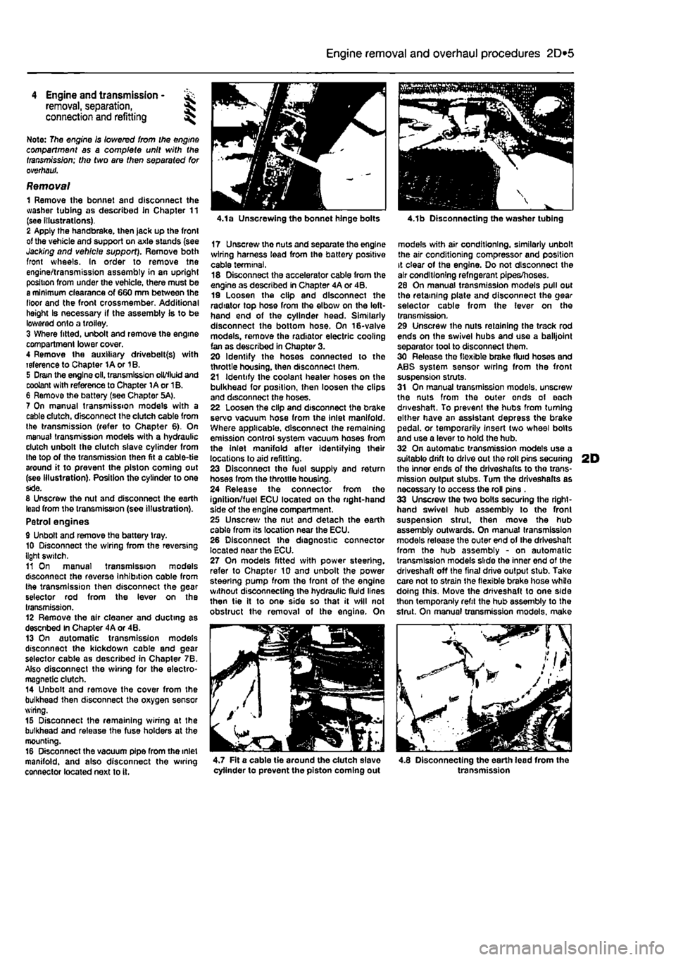
Removal 1 Remove the bonnet and disconnect the washer tubing as described in Chapter 11 (see illustrations). 2 Apply the handbrake, then jack up the front of the vehicle and support on axle stands (see Jacking and vehicle support). Remove both front wheels. In order to remove tne engine/transmission assembly in an upright position from under the vehicle, there must be a minimum clearance of 660 mm between the floor and the front crossmember. Additional height Is necessary if the assembly is to be lowered onto a trolley. 3 Where fitted, unbolt and remove the engine compartment lower cover. 4 Remove the auxiliary drivebelt(s) with reference to Chapter 1A or 1B. 5 Dram the engine oil. transmission oil/fluid and coolant with reference to Chapter 1A or 1B. 6 Remove the battery (see Chapter 5A). 7 On manual transmission models with a cable dutch, disconnect the clutch cable from the transmission (refer to Chapter 6). On manual transmission models with a hydraulic clutch unbolt the clutch slave cylinder from the top of the transmission then fit a cable-tie around it to prevent the piston coming out (see Illustration). Position the cylinder to one side. 8 Unscrew the nut and disconnect the earth lead from the transmission (see illustration). Petrol engines 9 Unbolt and remove the battery tray. 10 Disconnect the wiring from the reversing light switch. 11 On manual transmission models disconnect the reverse Inhibition cable from the transmission then disconnect the gear selector rod from the lever on the transmission. 12 Remove the air cleaner and ducting as descnbed In Chapter 4A or 4B. 13 On automatic transmission models disconnect the kickdown cable and gear selector cable as described in Chapter 7B. Also disconnect the wiring for the electro-magnetic clutch. 14 Unbolt and remove the cover from the bulkhead then disconnect the oxygen sensor wiring. 15 Disconnect the remaining wiring at the bulkhead and release the fuse holders at the mounting. 16 Disconnect the vacuum pipe from the inlet manifold, and also disconnect the wiring connector located next to it.
4.1a Unscrewing the bonnet hinge bolts
17 Unscrewthenutsandseparatetheengine wiring harness lead from the battery positive cable terminal. 18 Disconnect the accelerator cable from the engine as described in Chapter 4A or 4B, 19 Loosen the clip and disconnect the radiator top hose from the elbow on the left-hand end of the cylinder head. Similarly disconnect the bottom hose. On 16-valve models, remove the radiator electric cooling fan as described in Chapter 3. 20 Identify the hoses connected to the throttle housing, then disconnect them. 21 Identify the coolant heater hoses on the bulkhead for position, then loosen the clips and disconnect the hoses. 22 Loosen the clip and disconnect the brake servo vacuum hose from the Inlet manifold. Where applicable, disconnect the remaining emission control system vacuum hoses from the Inlet manifold after Identifying their locations to aid refitting. 23 Disconnect tho fuel supply and return hoses from the throttle housing. 24 Release the connector from the ignition/fuel ECU located on the right-hand side of the engine compartment. 25 Unscrew the nut and detach the earth cable from its location near the ECU. 26 Disconnect the diagnostic connector located near the ECU. 27 On models fitted with power steering, refer to Chapter 10 and unbolt the power steering pump from the front of the engine without disconnecting the hydraulic fluid lines then tie It to one side so that it will not obstruct the removal of the engine. On
4.1b Disconnecting the washer tubing
models with air conditioning, similarly unbolt the air conditioning compressor and position it clear of the engine. Do not disconnect the air conditioning refngerant pipes/hoses. 26 On manual transmission models pull out the retaining plate and disconnect the gear selector cable from the lever on the transmission. 29 Unscrew the nuts retaining the track rod ends on the swivel hubs and use a balljoint separator tool to disconnect them. 30 Release the flexible brake fluid hoses and ABS system sensor wrring from the front suspension struts. 31 On manual transmission models, unscrew the nuts from the outer ends of each driveshaft. To prevent the hubs from turning either have an assistant depress the brake pedal, or temporarily Insert two wheel bolts and use a lever to hold the hub. 32 On automatic transmission models use a suitable drift to drive out Ihe roll pins securing 2D the inner ends of the drlveshafts to tho trans-mission output stubs. Turn the driveshalts as necossary to access the roll pins . 33 Unscrew the two bolts securing the right-hand swivel hub assembly to the front suspension strut, then move the hub assembly outwards. On manual transmission models release the outer end of the driveshaft from the hub assembly - on automatic transmission models slide the inner end of the driveshaft off the final drive output stub. Take care not to strain the flexible brake hose while doing this. Move the driveshaft to one side thon temporanly refit the hub assembly to the strut. On manual transmission models, make
^ - / //
4.7 Fit a cable tie around the dutch slave cylinder to prevent the piston coming out 4.8 Disconnecting the earth lead from the transmission
Page 98 of 225
2D*10 Engine removal and overhaul procedures
05 Remove the brush holder assembly from the automatic transmission as described in Chapter 7B, Section 4. The brushes bear on the slip rings at the rear of the electro-magnetic clutch housing and they may be damaged when the transmission is removed. 86 Unscrew and remove the transmission-to-engine bolts then carefully draw the transmission away from the engine, resting It securely on wooden blocks. Collect the locating dowels If they are loose enough to be extracted, 87 If the oil pump driveshaft remains engaged with the crankshaft, remove it and reert Into the transmission to protect It from damage.
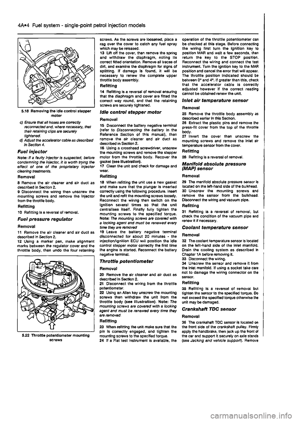
Connection 86 If the engine and transmission have not been separated, go to paragraph 104. Manual transmission models 89 Smear a little high-melting-point grease
on
the splines of the transmission input shaft. Do not use an excessive amount as there Is the risk of contaminating the clutch friction plate. 90 Carefully offer up the transmission to the engine cylinder block, guiding the input shaft through the clutch friction plate. 91 Refit the transmission-to-engine bolts and
the
single nut. hand^jghtenlng 1hem to secure the transmission in position. Note: Do not hghten them to force the engine and transmission together. Ensure that the beilhousing and cylinder block mating faces will butt together evenly without obstruction, before finally tightening the bolts and nut securely. Automatic transmission models 92 Check that the oil pump driveshaft is correctly engaged with the oil pump in the transmission. 93 Carefully offer up the transmission to Ihe rear of the engine and insert the oil pump driveshaft In the centre of the electro-magnetic clutch housing. Locate the transmission on the locating dowels then Insert the bolts and tighten them securely. 94 Refit the brush holder assembly to the automatic transmission with reference to Chapter 7B, Section 4. Petrol engines 96 Refit the transmission lower cover and tighten the bolts. 96 Locate the support bracket on the lower cover, then insert the bolts hand-tight. Also Insert the bolts securing the bracket lo the rear of Ihe cylinder block. With all the bolts Inserted, tighten them securely. 97 Refit the earth leads and tighten the bolts. Diesel engines 98 Refit the rpm sensor and tighten the bolts. 99 Insert the Intermediate shaft through the bracket then locate the dust boot on it and insert the Inner end in the transmission.
100 Refit and tighten the bolts securing the Intermediate shaft to the bracket on the rear of the cylinder block. 101 Refit the transmission lower cover and tighten the bolts. Ail models 102 Refit the starter motor (see Chapter 5A). 103 Refit the wiring harness to the components on the engine/transmission assembly making sure it is routed correctly.
Refitting 104 Locate the engine/transmission assembly beneath the engine compartment and attach the hoist to the lifting eyes. 105 Carefully lift the assembly up into the engine compartment taking care not to damage the surrounding components. 106 Reconnect the left-hand engine/trans-mission mounting to the body and tighten the bolts. 107 Reconnect Ihe right-hand engine mounting to the body and tighten the bolts. 108 Working beneath the vehicle, refit the rear engine mounting and tighten the bolts. 109 Disconnect the hoist from the engine and transmission lifting eyes and remove the hoist from under the vehicle. 110 The remainder of the refitting procedure is the direct reverse of the removal procedure, noting the following points:
a) Ensure that alf sections of the wiring harness follow their original routing; use new cable-ties to secure the harness In position, keeping it away from sources
of
heat and abrasion. b) On vehicles with manual transmission check and if necessary adjust the gearchenge cable and rod with reference to Chapter 7A. c) On vehicles with automatic transmission use new ro//p/ns fo secure the driveshafts to the transmission output stubs. Also check and if necessary adjust the kickdown end selector cables with reference to Chapter 78. d) Ensure that afi hoses are correctly routed and are secured with the correct hose clips, where applicable. If the hose clips cannot be used again; proprietary worm drive clips should be fitted
In
their place. e) Refill the cooling system as described in Chapter 1A or 18. f) Refill the engine with appropriate grades and quantities of oil (Chapter
1A
or 1B). g) Refit and adjust the auxiliary drivebelt(s) wfth reference fo Chapter 1A or 1B. h) Check and If necessary adjust the accelerator cable with reference to Chapter
AA,
48 or
AC.
i) When the engine is started for the first time, check for
air,
coolant, lubricant and fuel leaks from manifolds, hoses etc. If
the
engine has been overhauled, read
the
notes In Section 13 before attempting to starlit.
5 Engine overhaul • dismantling sequence
1 It is much easier to dismantle and work on the engine if it is mounted on a portable engine stand. These stands can often be hired from a tool hire shop. Before the engine is mounted on a stand, the flywheel should be removed, so that the stand bolts can be tightened Into the end of the cylinder block/crankcase. 2 If a stand Is not available, it Is possible to dismantle the engine with it blocked up on a sturdy workbench, or on the floor, Be very careful not to tip or drop the engine when working without a stand. 3 If you intend to obtain a reconditioned engine, all anclllarles must be removed first, to be transferred to the replacement engine (just as they will If you are doing a complete engine overhaul yourself). These components Include the following:
Petroi engines a) Power steering pump if removed with the engine (Chapter
10).
b) Alternator fmcluding mounting brackets) and starter motor (Chapter
SA).
c) The Ignition system and HT components including ail sensors, HT leads and
spark
plugs (Chapters 1A and
SB).
d) The fuel injection system components (Chapters A A and
AB).
e) All electrical switches, actuators and sensors, and the engine wiring harness (Chapters 4A, AB, SB). f) Inlet and exhaust manifolds (Chapters 4A, AB end
AD).
g) Engine oil dipstick and tube. h) Engine mountings (Chapter
2A).
i) Flywheef/driveptate (Chapter
2A).
j) Clutch components (Chapter
6)
- manual transmission. k) Electro-magnetic clutch components (Chapter 7B) - automatic transmission. I) Cooling system components (Chapter
3).
Diesei engines a) Power steering pump //removed with the engine (Chapter
10).
b) Alternator (Including mounting brackets) and starter motor (Chapter 5A). c) The glow plugfpre-heatlng system components (Chapter
SC).
d) Ait fuel system components, including the fuel injection pump, all sensors and actuators (Chapter
AC).
e) The vacuum pump. f) Ail electrical switches, actuators and sensors, and the engine wiring harness (Chapter 4C and 5C). g) Inlet and exhaust manifolds and, where applicable, the turbocharger (Chapter
AC
and 4D). h) The engine oil level dipstick and its tube. i) Engine mountings (Chapter
2C).
Page 105 of 225
2D*10 Engine removal and overhaul procedures
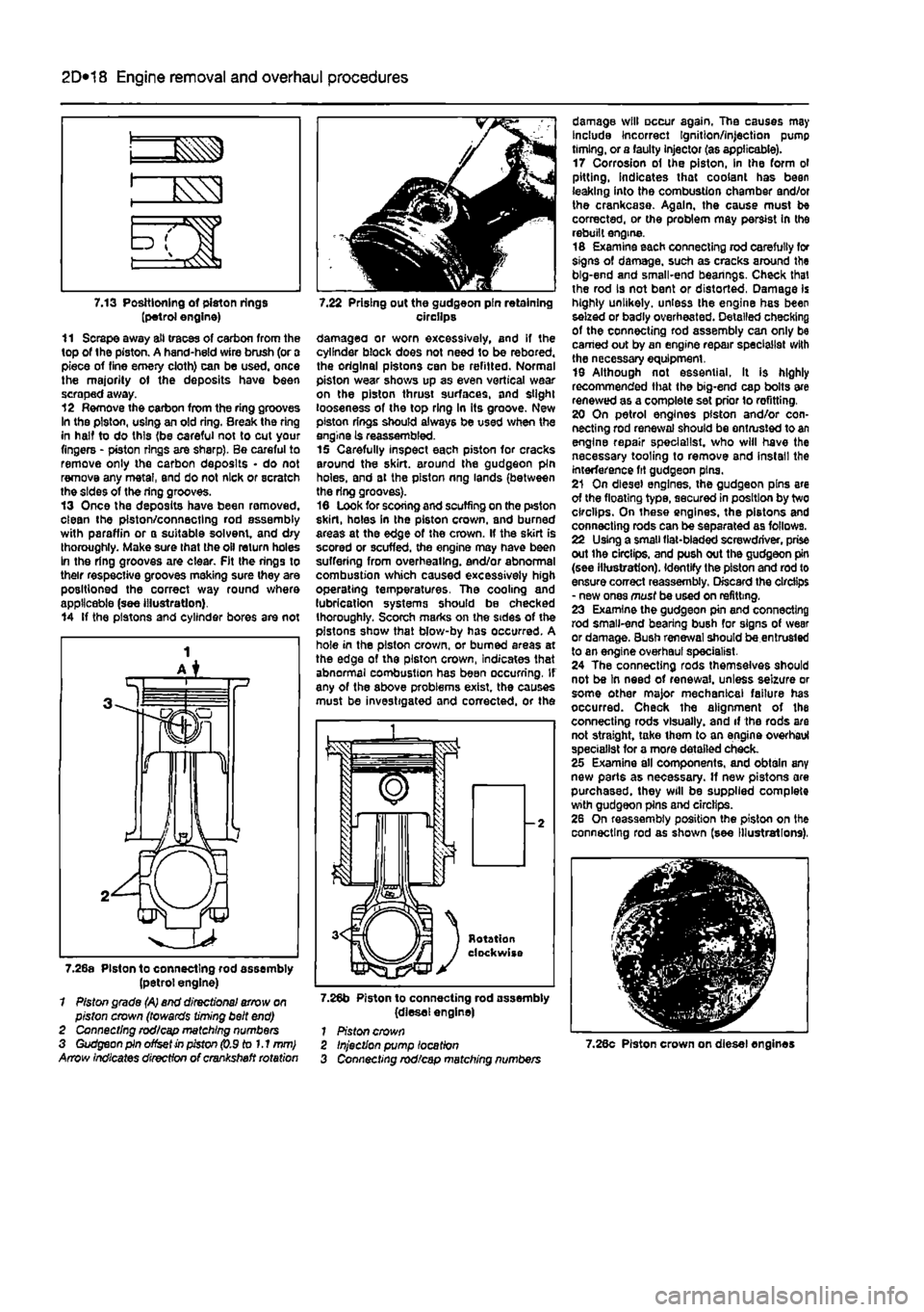
7.13 Positioning of piston rings (petrol engine) 11 Scrape away all traces of carbon from the top of the piston. A hand-held wire brush (or a piece of fine emery cloth) can be used, once the majority ot the deposits have been scraped away. 12 Remove the carbon from the ring grooves In the piston, using an old ring. Break the ring in half to do this (be careful not to cut your fingers - piston rings are sharp). Be careful to remove only the carbon deposits • do not remove any metal, end do not nick or scratch the sides of the ring grooves. 13 Once the deposits have been removed, clean the piston/connecting rod assembly with paraffin or o suitable solvent, and dry thoroughly. Make sure that the oil return holes In the ring grooves are clear. Fit the rings to their respective grooves meking sure they are positioned the correct way round where applicable (see illustration). 14 If the pistons and cylinder bores are not
7.22 Prising out the gudgeon pin retaining circilps damagea or worn excessively, and if the cylinder block does not need to be rebored. the original pistons can be refitted. Normal piston wear shows up as even vertical wear on the piston thrust surfaces, and slight looseness of the top ring In its groove. New piston rings should always be used when the engine is reassembled. 15 Carefully inspect each piston for cracks around the skirt, around the gudgeon pin holes, and at the piston nng lands (between the ring grooves). 16 Look for scoring and scuffing on the ptston skirt, holes in the piston crown, and burned areas at the edge of the crown. If the skirt is scored or scuffed, the engine may have been suffering from overheating, end/or abnormal combustion which caused excessively high operating temperatures. The cooling and lubrication systems should be checked thoroughly. Scorch marks on the sides of the pistons show that blow-by has occurred. A hole in the piston crown, or burned areas at the edge of the piston crown, Indicates that abnormal combustion has been occurring. If any of the above problems exist, the causes must be investigated and corrected, or the
7.26a Piston to connecting rod assembly (petrol engine) 1 Piston grade (A) end directional arrow on piston crown (towards timing belt end) 2 Connecting rod/cap matching numbers 3 Gudgeon pin offset in piston (0.9 to 1.1 mm) Arrow indicates direction of crankshaft rotation
7.26b Piston to connecting rod assembly (diesel engine) 1 Piston crown
damage will occur again. The causes may Include Incorrect Ignition/injection pump timing, or a faulty injector (as applicable). 17 Corrosion of the piston, in the form ol pitting, indicates that coolant has been leaking into the combustion chamber and/or the crankcase. Again, the cause must be corrected, or the problem may persist In the rebuilt engine. 16 Examine each connecting rod carefully for signs of damage, such as cracks around the big-end and small-end bearings. Check that the rod is not bent or distorted, Damage is highly unlikely, unless the engine has been seized or badly overheated. Detailed checking of the connecting rod assembly can only be earned out by an engine repair specialist with the necessary equipment. 19 Although not essential. It is highly recommended that the big-end cap bolts are renewed as a complete set prior lo refitting. 20 On petrol engines piston and/or con-necting rod renewal should be entrusted to an engine repair specialist, who will have the necessary tooling to remove and install the interference fit gudgeon pins. 21 On diesel engines, the gudgeon pins are of the floating type, secured in position by two circlips. On these engines, the pistons and connecting rods can be separated as follows. 22 Using a small fiat-bladed screwdriver, prise out ihe circlips, and push out the gudgeon pin (see illustration). Identify the piston and rod to ensure correct reassembly. Discard the circlips - new ones must be used on refitting. 23 Examine the gudgeon pin and connecting rod small-end bearing bush for signs of wear or damage. Bush renewal should be entrusted to an engine overhaul specialist. 24 The connecting rods themselves should not be In need of renewal, unless seizure or some other major mechanical failure has occurred. Check the alignment of the connecting rods visually, and if the rods are not straight, take ihem to an engine overhaul specialist for a more detailed check. 25 Examine all components, and obtain any new parts as necessary. If new pistons are purchased, they will be supplied complete with gudgeon pins and circlips. 26 On reassembly position the piston on the connecting rod as shown (see Illustrations),
Injection pump location Connecting rod/cap matching numbers 7.28c Piston crown on diesel engines
Page 111 of 225
2D*10 Engine removal and overhaul procedures
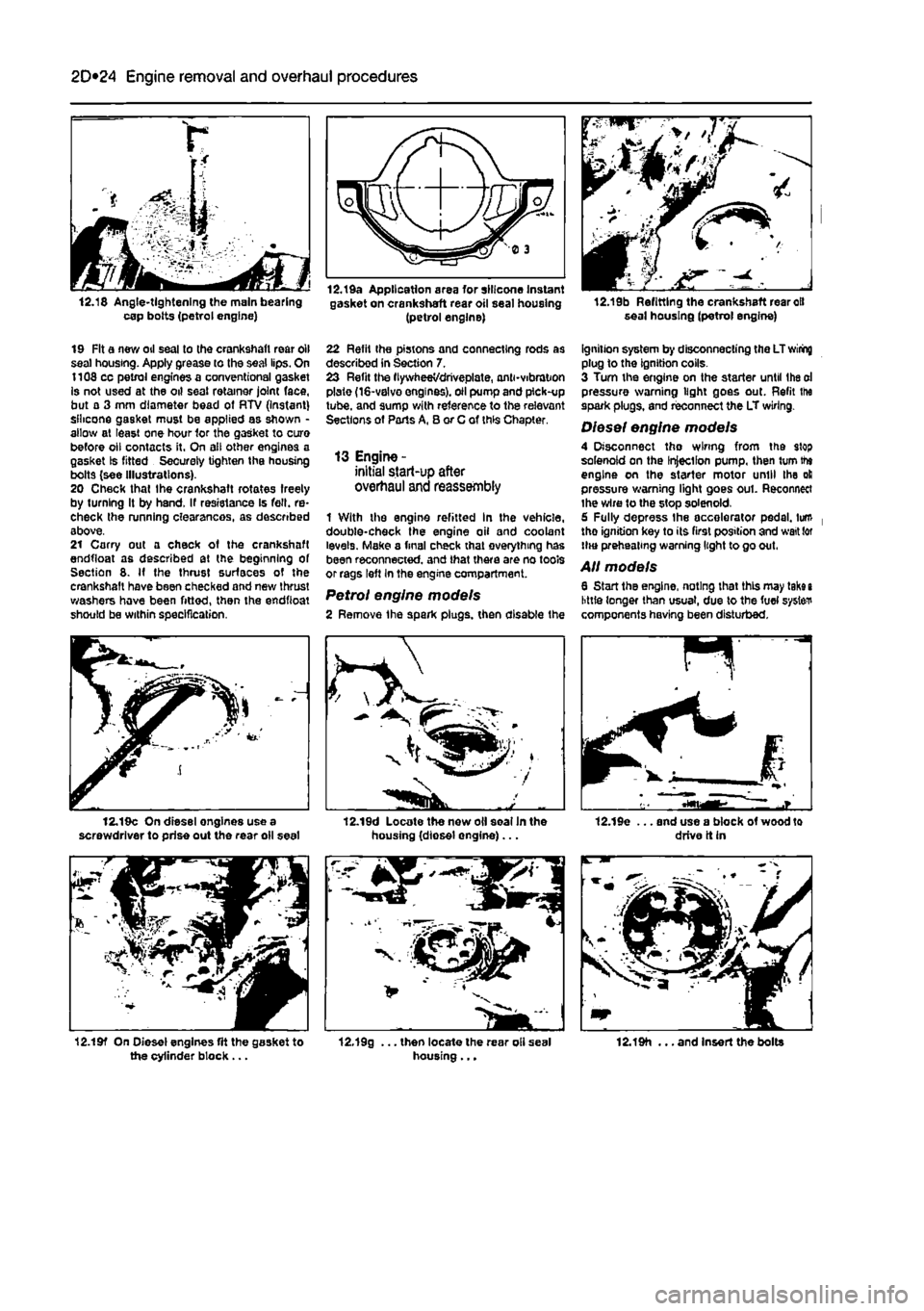
12.18 Angle-tightening the main bearing cap bolts (petrol engine)
12.Ida Application area for silicone Instant gasket on crankshaft rear oil seal housing (petrol engine) 12.19b Refitting the crankshaft rear oil seal housing (petrol engine)
19 Fit a new oil seal to the crankshaft rear oil seal housing. Apply grease to the seal lips. On 1108 cc petrol engines a conventional gasket Is not used at the oil seal retainer joint face, but a 3 mm diameter bead of RTV (Instant) silicone gasket must be applied as shown -allow at least one hour 1or the gasket to cure before oil contacts it. On all other engines a gasket Is fitted Securely tighten the housing bolts (see Illustrations). 20 Check that Ihe crankshaft rotates freely by turning It by hand. If resistance Is fell, re-check the running clearances, as described above. 21 Carry out a check of the crankshaft endfloat as described at the beginning of Section 8. If the thrust surfaces of the crankshaft have been checked and new thrust washers hove been fitted, then the endfioat should be within specification.
22 Refit the pistons and connecting rods as described in Section 7. 23 Refit the flywheeVdriveplate, and-vibration plate (16-valvo engines), oil pump and pick-up tube, and sump with reference to the relevant Sections of Parts A, B or C of this Chapter.
13 Engine -initial start-up after overhaul and reassembly
1 With the engine refitted In the vehicle, double-check the engine oil and coolant levels. Make a final check that everything has been reconnected, and that there are no tools or rags left In the engine compartment.
Petrol engine models 2 Remove the spark plugs, then disable the
ignition system by disconnecting the LT wiring plug to the ignition colls. 3 Turn the engine on the starter until Ihe oi pressure warning light goes out. Refit ihe spark plugs, and reconnect the LT wiring.
Diesel engine models 4 Disconnect tho wiring from the stop solenoid on the Injection pump, then turn the engine on the starter motor until the oil pressure warning light goes out. Reconnect ihe wire to the stop solenoid. 6 Fully depress the accelerator pedal, turn tho ignition key to its first position and wait tor HHJ preheating warning light to go out.
All models 6 Start the engine, noting that this may take i little longer than usual, due to the fuel system components having been disturbed.
12.19c On diesel engines use a screwdriver to prise out the rear oil seal 12.19d Locate the new oil soalln the housing (diosel engine)... 12.19e ... and use a block of wood to drive it in
12.19f On Diesel engines fit the gasket to the cylinder block ... 12.19g ... then locate the rear oli seal housing... 12.19h ... and Insert the bolts
Page 114 of 225
3*2 Cooling, heating and ventilation systems
1 General information and precautions
Genera/ Information The engine cooling/cabin heating system is ol pressurised type, comprising a coolant pump driven by the camshaft timing belt (petrol engine models) or auxiliary drlvebelt (diesel engine models), a crossllow radiator, a coolant expansion tank, an electric cooling fan, a thermostat, heater matrix, and all associated hoses and switches. The system functions as follows: Ihe coolant pump circulates cold water around the cylinder block and head passages, and through the Inlet manifold, heater matrix and throttle body to the thermostat housing. When the engine Is cold, the thermostat remains closed and prevents coolant from circulating through the radiator. When the coolant reaches a predetermined temperature, the thermostat opens, and the coolant passes through the top hose to the radiator. As the coolant circulates through the radiator, it is cooled by the in-rush of air when the car is in forward motion. The airllow is supplemented by the action of the electric cooling fan. when necessary, As the temperature of the coolant in the radiator drops, it flows to the bottom of the radiator by convection, and passes out through the bottom hose to the coolant pump - the cycle is then repeatod, When the engine is at normal operating temperature, the coolant expands, and some of It is displaced into the expansion tank. Coolant collects In the tank, and ts returned to Ihe radiator when the system cools. On petrol engine models, the expansion tank is integrated into the side of the radiator. On diesel engine models, and certain petrol engine models with air conditioning, the tank is a separate unit, mounted on the right hand side of the engine compartment. On turbo diesel engine models, the coolant is also passed through a supplementary engine oil cooler, to assist In controlling the engine lubricant temperature. Tho electric cooling fan mounted in front of the radiator is controlled by a thermostatic switch. At a predetermined coolant temperature, the swilch/sensor actuates the tan lo provide additional airflow through the radiator, The switch cuts the electrical supply to the Ion when the coolant temperature has dropped below a preset threshold (see Specifications).
Precautions
A
Warning: Do not attempt to remove the expansion tank pressure cap, or to disturb any part of the cooling system, whlio the engine is hot, as then is a high risk of scalding, tf the expansion tank pressure cap must be removed before the
engine and radiator have fulty cooled (even though this is not recommended?, the pressure in the cooling system must first be relieved. Cover the cap with a thick layer of cloth, to avoid scalding, and slowly unscrew the pressuro cap until a hissing sound Is heard. When the hissing stops, indicating that the pressure has reduced, slowly unscrew the pressure cap until it can be removed; If more hissing sounds are heard, wait until they have stopped before unscrewing the cap completely. At all times, keep your face well away from the pressure cap opening, and protect your hands.
A
Warning: Do not allow antifreeze to come into contact with your skin, or with the painted surfaces of the vehicle. Rinse off spills immediately, with plenty of water. Never leave antifreeze lying around in an open container, or In a puddle In the driveway or on the garage floor. Children and pets are attracted by its sweet smell, but antifreeze can be fatal tf ingested.
A
Warning: If the engine is hot, the electric cooling fan may start rotating even if the engine and ignition are switched off. Be careful to keep your hands, hair, and any loose clothing well clear when working In the engine compartment.
2 Cooling system hoses - f&> disconnection and renewal ^
1 The number, routing and pattern of hoses will vary according to model, but the same basic procedure applies. Before commencing work, make sure that the new hoses are to hand, along wilh new hose clips if needed, it is good practice to renew the hose clips at the same time as the hoses. 2 Drain the cooling system, as described in Chapter 1A or 18, saving the coolant if it is fit for re-use. Apply a little penetrating oil onto the hose clips if they are corroded. 3 Release the hose clips from the hose concerned. Three types of clip are used; worm-drive. spring and 'sardine-can'. The worm-drive clip is released by turning its screw anti-clockwise. The spring clip Is released by squeezing Its tags together with pliers, at the same time working the cbp away from the hose stub. The sardine-can clips are not re-usable, and are best cut off with snips or side cutters. 4 Unclip any wires, cables or other hoses which may be attached to the hose being removed. Make notes for reference when reassembling If necessary. 5 Release the hose from its stubs with a twisting motion. Be careful not to damage the stubs on deltcate components such as the radiator, or thermostat housings. If the hose Is stuck fast, the best course is often to cut it off using a sharp knife, but again be careful not to damage the stubs.
6 Before fitting the new hose, smear the stubs with washing-up liquid or a suitable rubber lubricant to aid fitting. Do not use oil or grease, which may attack the rubber. 7 Fit the hose clips over the ends of the hose, then fit the hose over its stubs. Work the hose Into position. When satisfied, locate and tighten the hose dips. 6 Refill the cooling system as described In Chapter 1A or 1B. Run the engine, and chock that there are no leaks. 9 Recheck the tightness of Ihe hose clips on any new hoses after a few hundred miles. 10 Top-up the coolant level if necessary.
3 Radiator -
removal,
inspection and refitting
Removal Note: If leakage is the reason for removing
the
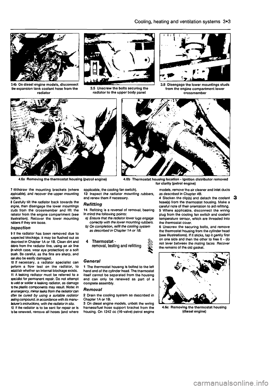
radiator, bear In mind that minor leaks can often be cured using proprietary radiator sealing compound, with the radiator in situ. 1 Disconnect the battery negative terminal (refer to Disconnecting the battery In the Reference Section of this manual). On diesel engine models, unbolt the relay bracket from the side of the battery tray. 2 Drain the cooling system as described In Chapter 1A or 1B. 3 On 1242 cc (16-valve) petrol engine models, remove the air cleaner and Inlet ducts as desenbed In Chapter 4B, 4 Slacken the clips and disconnect Ihe (op and bottom coolant hoses from the radiator. In addition on diesel engine models, and petrol engine models with a remotely-sited expansion tank, disconnect the expansion tank coolant hose from the right hand side ol the radiator (see Illustrations), 5 Unscrew the fixings and lift the plastic trim panel from above the front bumper Unscrew the bolt(s) securing tho radiator to the upper body panel (see Illustration). Note that the radiator and cooling fan assembly share the same upper mounting bolt. 6 Unbolt the cooling fan(e) and shroud assembly from Ihe rear ot the radiator, as described in Section 5.
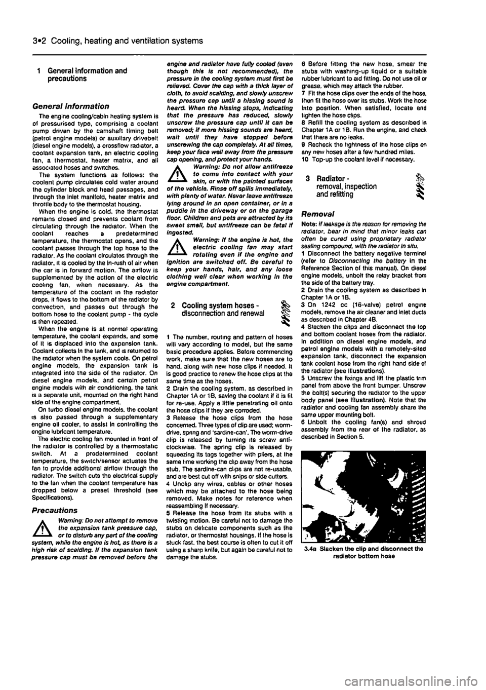
3.4a Slacken the clip and disconnect the radiator bottom hose
Page 115 of 225
3*2 Cooling, heating and ventilation systems
3.4b On diesel engine models, disconnect the expansion tank coolant hose from the radiator 3.5 Unscrew the bolts securing the radiator to the uppor body panel
3.8 Disengage the lower mountings studs from the onglne compartment lower crossmember
4.6a Removing the thermostat housing (petrol engine) 4.6b Thermostat housing location - Ignition distributor removed for clarity (petrol engine) ? Withdraw the mounting brackets (where applicable), and recover the upper mounting rubbers. 8 Carefully tilt the radiator back towards the engine, then disengage the lower mountings studs from the crossmember and lift the radiator from the engine compartment (see illustration). Recover the lower mounting rubbers if they are loose. Inspect/on 9II the radiator has been removed due to suspected blockage, it may be flushed out as descnbed in Chapter lAor 10. Clean dirt and debris from the radiator fins, using an air line fn which case, wear eye protection) or a soft Brush. Be careful, as the fins are sharp, and
can
also be easily damaged. ID If necessary, a radiator specialist can perform a flow test on the radiator, to establish whether an internal blockage exists. 11 A leaking radiator must be referred to a specialist for permanent repair. Do not attempt to weld or solder a leaking radiator, as damage to the plastic components may result. Note: In
an emergency,
minor
leaks
from the radiator can often be cured by using a suitable radiator seat'ng compound, in accordance with its manu-
facturer's
instructions, with the radiator in situ. 12 If the radiator is to be sent for repair or is
to
be renewed, remove all hoses (and where
applicable, the cooling fan switch). 13 Inspect Ihe radiator mounting rubbers, and renew them if necessary. Refitting 14 Refitting is a reversal of removal, bearing in mind the following points: a) Ensure that the radiator lower lugs engage correctly with the lower mounting rubbers. b) On completion, refill the cooling system as described in Chapter 1A or IB.
Thermostat - Jk removal, testing and refitting #
General 1 The thermostat housing Is bolted to the left hand end of the cylinder head. The thermostat itself cannot be separated from the housing and can only be renewed as part of a complete assembly.
Removal 2 Drain the cooling system as described in Chapter 1A or 1B. 3 On diesel engine models, unbolt the wiring harness/fuel hose support bracket from the housing. On 1242 cc (16-valve) petrol engine
models, remove the air cleaner and inlet ducts as descnbed in Chapter 4B. 4 Slacken the clipfs) and detach the coolant hose(s) from the thermostai housing, Make a careful note of their orientation to aid refitting. 5 Where applicable, disconnect the wiring plug from the cooling fan switch and coolant temperature sensor, which are threaded into the thermostat cover. 6 Unscrew the securing bolts, and remove the thermostat housing from the cylinder head (see illustrations). If it sticks, tap it gently first on one side and then the other to free it - do not lever between the mating faces. Recover the remains of the old c,
4.6c Removing the thermostat housing (diesel engine)
Page 121 of 225
4A«1
Chapter 4 Part A:
Fuel system - single-point petrol injection models
Contents
Accelerator cable • removal, refitting and adjustment 4 Air cleaner and inlet system - removal and refitting 2 Air cleaner filter element renewal See Chapter 1A Engine management system components - removal 8nd refitting .. 5 fuel filter renewal See Chapter 1A Fuel injection system - depressurlsatlon 8 Fuel injection system • testing and adjusting 10
Degrees of difficulty
Fuel pump/fuel gauge sender unit - removal and refitting 8 Fuel tank - removal and refitting 7 General information and precautions 1 Idle speed and mixture adjustment See Chapter 1A Inlet air temperature regulator • removal and refitting 3 Inlet manifold - removal and refitting 9 Unleaded petrol - general Information and usage 11
Easy, suitable for Fairty easy, suitable Fairly difficult, Jx suitable for competent ^ OY mechanic ^
DifficUt, suitable tor % Very difficult, ^ novice with Me for begrmer with &
Fairly difficult, Jx suitable for competent ^ OY mechanic ^ experienced DIY > * suitable for expert D(Y JS or professional ^ experience some experience &
Fairly difficult, Jx suitable for competent ^ OY mechanic ^ mechanic > * suitable for expert D(Y JS or professional ^
Specifications
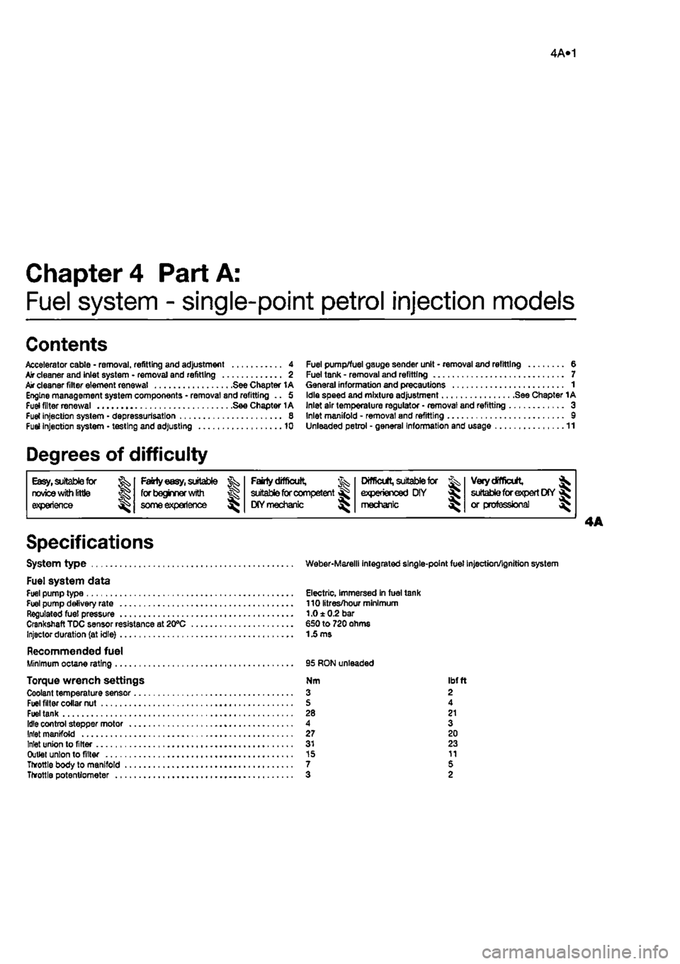
System type Weber-Marelll integrated single-point fuel injection/ignition system
Fuel system data Fuel pump type Electric, Immersed in fuel tank Fuel pump delivery rate 110 litres/hour minimum Regulated fuel pressure 1.0 ± 0.2 bar Crankshaft TDC sensor resistance at 20°C €50 to 720 ohms Injector duration (at idle)
1
£ ms
Recommended fuel Minimum octane rating 95 RON unleaded
Torque wrench settings Nm ibfft Coolant temperature sensor 3 2 Fuel filter collar nut S 4 Fuel tank 28 21 Idle control stepper motor 4 3 Inlet manifold 27 20 Inlet union to filter 31 23 Outlet union to filter 15 11 Throttle body to manifold 7 5 Throttle potentiometer 3 2
Page 122 of 225
4A*2 Fuel system - single-point petrol Injection models
1 General information and precautions
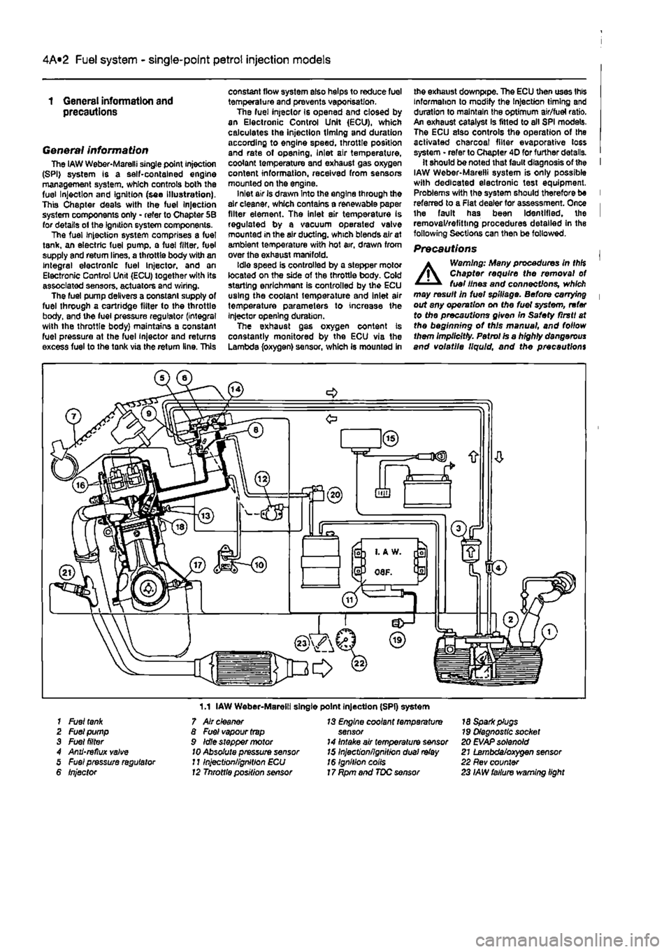
General information The iAW Weber-Marelli single point Injection (SPI) system is a self-contained engine management system, which controls both the fuel Injection and Ignition (see Illustration), This Chapter deals with the fuel Injection system components only - refer to Chapter 5B for details ol the ignition system components. The fuel Injection system comprises a fuel tank, an electric fuel pump, a fuel filter, fuel supply and return lines, a throttle body with an integral electronic fuel Injector, and an Electronic Control Unit (ECU) together with its associated sensors, actuators and wiring. The fuel pump delivers a constant supply of fuel through a cartridge fitter to the throttle body, and the fuel pressure regulator (integral with the throttle body) maintains a constant fuel pressure at the fuel injector and returns excess fuel to the tank via the return line. This
constant flow system also helps to reduce fuel temperature and prevents vaporisation. Tne fuel injeclor Is opened and closed by an Electronic Control Unit (ECU), which calculates the injection timing and duration according to engine speed, throttle position and rate of opening, Inlet air temperature, coolant temperature and exhaust gas oxygen content information, received from sensors mounted on the engine. inlet air is drawn Into the engine through the air cleaner, which contains a renewable paper filter element. The inlet air temperature is regulated by a vacuum operated valve mounted in the air ducting, which blends air at ambient temperature with hot air, drawn from over the exhaust manifold. Idle speed is controlled by a stepper motor located on the side of the throttle body. Cold starling enrichment is controlled by the ECU using the coolant temperature and inlet air temperature parameters to increase the injector opening duration. The exhaust gas oxygen content is constantly monitored by the ECU via the Lambda (oxygen) sensor, which is mounted in
me exhaust downpipe. The ECU then uses this Information to modify the Injection timing and duration to maintain the optimum air/fuel ratio. An exhaust catalyst Is fitted to all SPI models. The ECU also controls the operation of the activated charcoal filter evaporative loss system • refer to Chapter 4D for further details. It should be noted that fault diagnosis of the I IAW Weber-Marelli system is only possible with dedicated electronic test equipment. Problems with the system should therefore be I referred to a Flat dealer for assessment. Once i the fault has been Identified, the I removal/refitting procedures detailed in the following Sections can then be followed.
Precautions |
A
Warning: Many procedures in thH Chapter require the removal ot fuel lines and connections, which may result in fuel spillage. Before carrying | out any operation on Me fuel system, refer to the precautions given In Safety flrstt at the beginning ot this manual, and follow them Implicitly. Petrol Is a highly dangerous and volatile liquid, and the precautions
1.1 IAW Weber-Marelli single point Injection (SPI) system 1 Fuel
tank
2 Fuel pump 3 Fuel filter 4 Anii'reflux valve 5 Fuel pressure regulator 6 Injector
7 Air cleaner 8 Fuel vapour
trap
9 Idle stepper motor
10
Absolute pressure sensor J11njection/ignition ECU 12 Tnrottle position sensor
13 Engine coolant temperature sensor 14 Intake air temperature sensor 15 Inject'onfignitron dual
relay
16 Ignition coils 17 Rpm and TDC sensor
18 Spark plugs 79 Diagnostic socket 20 EVAP solenoid 21 Lambda/oxygen sensor 22 Rev counter 23 IAW failure warning light
Page 124 of 225
4A*2 Fuel system - single-point petrol Injection models
motor c) Ensure that all hoses are correctly reconnected and, where necessary, that their retaining clips are securely tightened. d) Adjust the accelerator cable as described In Section 4.
Fuel injector Note: If a faulty Injector Is suspected, before condemning the Injector, it is worth vying the effect of one of the proprietary Injector cleaning treatments. Removal 8 Remove the air cleaner and air duct as described In Section 2. 9 Disconnect the wiring then unscrew the mounting screws and remove Ihe Injector from the throttle body. Refitting 10 Refitting is a reversal of removal.
Fuel pressure regulator
Removal 11 Remove Ihe air cleaner and air duel as described In Section 2. 12 Using a marker pen. make alignment marks between the regulator cover end the throttle body, then undo the four retaining
screws. As the screws are loosened, place a rag over the cover to catch any fuel spray which may be released. 13 Lift off the cover, then remove the spring and withdraw the diaphragm, noting Its correct fitted orientation. Remove all traces of dirt, and examine the diaphragm for signs of splitting. If damage Is found, it will be necessary to renew the complete upper throttle body assembly. Refitting 14 Refitting is a reversal of removal ensuring that the diaphragm and cover are fitted the correct way round, and that the retaining screws are securely tightened,
Idle control stepper motor
Removal 15 Disconnect the battery negative terminal (refer to Disconnecting the battery In the Reference Section of this manual), then remove the air cleaner and air duct as described in Section 2. 16 Using a crosshead screwdriver, unscrew the mounting screws and remove the stepper motor from the throttle body. Recover the gaskei (see illustration). 17 Clean the unit and check for damage and wear. Refitting 18 When refitting the unit use a new gasket and make sure that the plunger is inserted correctly using the following procedure. Insert the unit and refit the mounting screws loosely. Reconnect the wiring then switch on the ignition several times so that the unit centralises itself. Finally fully tighten the mounting screws to the specified torque. Note: The mounting screws are covered with a locking agent and must be renewed every time they are removed 19 Leave the battery negative terminal disconnected for about 20 minutes - the injection/ignition ECU will position the Idle control stepper motor correctly the first time the engine is started. Reconnect the battery negative terminal.
Throttle potentiometer
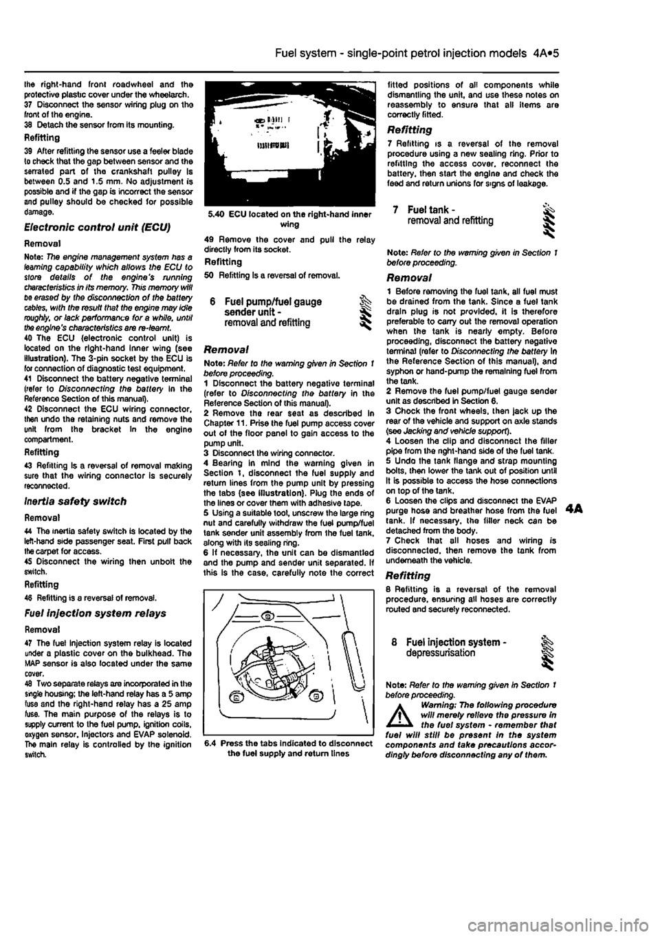
Removal 20 Remove the air cleaner and air duct as described in Section 2. 21 Disconnect the wiring from the throttle potentiometer. 22 Using an Allen key unscrew the mounting screws then withdraw the unit from the throttle body (see Illustration). Note: The mounting screws ere covered with a locking agent and must be renewed every time they are removed. Refitting 23 When refitting the unit make sure that the pin Is correctly engaged, and tighten the mounting screws to the specified torque. 24 If a Rat test Instrument is available, the
operation of the throttle potentiometer can be checked at this stage. Before connecting the wiring first turn Ihe ignition key to position MAR and wait a few seconds, then return the key to the STOP position, Reconnect the wiring and connect the test instrument. Turn the Ignition key to the MAR position and cancel the error that will appear. The throttle position Indicated should be between 0° and 4°. If greater than this, check thai the accelerator cable is correctly adjusted however If the correct reading cannot be obtained renew the unit.
Inlet air temperature sensor
Removal 25 Remove the throtlle body assembly as described earlier In this Section. 28 Extract the plastic pins and remove the press-fit cover from the top of the throttle body. 27 Invert the cover then unscrew the mounting screws and remove the Inlet air temperature sensor from the cover. Refitting 28 Refining Is a reversal of removal.
Manifold absolute pressure (MAP) sensor
Removal 29 The manifold absolute pressure sensor is located on the left-hand side of the bulkhead. 30 Unscrew the mounting screws and remove the sensor from the bulkhead, Disconnect the wiring and vacuum pipe. Refitting 31 Refitting is a reversal of removal, but check the condition of the vacuum pipe and renew it if necessary.
Coolant temperature sensor
Removal 32 The coolant temperature sensor Is located on the left-hand side of the inlet manifold. Drain the cooling system as described In Chapter 1A before removing it. 33 Disconnect the wiring. 34 Unscrew the sensor and remove It from the Inlet manifold. If using a socket take care not to damage Ihe wiring connector on the sensor. Refitting 35 Refitting Is a reversal of removal bui tighten Ihe sensor to the specified torque. Do not exceed the specified torque otherwise the unit may be damaged.
Crankshaft TDC sensor
Removal 36 The crankshaft TDC sensor Is located on the front side of the crankshaft pulley. Firmly apply the handbrake, then jack up the front of the car Bnd support It securely on axle stands (see Jacking end vehicle support). Remove 5.22 Throttle potentiometer mounting screws
Page 125 of 225
Ihe right-hand front roadwheel and the protective plastic cover under the wheelarch. 37 Disconnect the sensor wiring plug on the front of the engine. 38 Detach the sensor from its mounting. Refitting 39 After refitting Ihe sensor use a feeler blade to check that the gap between sensor and the serrated part of the crankshaft pulley Is between 0.5 and 1.S mm. No adjustment is possible and if the gap is incorrect the sensor and pulley should be checked for possible damage.
Electronic control unit (ECU)
Removal Note: 77ie engine management system has a (earning capability which allows the ECU to store details of the engine's running
characteristics
in its memory,
This
memory
will
tie erased by the disconnection of the battery
cables,
with the resuit that the engine may idle
roughly,
or lack performance for a while, until
the
engine's characteristics are re-teamt. 40 The ECU {electronic control unit) is located on the right-hand Inner wing (see illustration). The 3-pin socket by the ECU is for connection of diagnostic test equipment. 41 Disconnect the battery negative terminal (refer to D/sconnecffng the battery in the Reference Section of this manual). 42 Disconnect the ECU wiring connector, then undo the retaining nuts and remove the unit from the bracket In the engine compartment. Refitting 43 Refitting Is a reversal of removal making sure that the wiring connector is securely reconnected. Inertia safety switch
Removal 44 The inertia safety switch is located by the left-hand side passenger seat. First pull back
the
carpet for access. 45 Disconnect the wiring then unbolt the switch. Refitting 48 Refitting is a reversal of removal.
Fuel injection system relays
Removal 47 The fuel injection system relay is located under a plastic cover on the bulkhead. The MAP sensor is also located under the same cover. 48 Two separate relays are incorporated in the single housing; the left-hand relay has a 5 amp fuse and the right-hand relay has a 25 amp fuse. The main purpose of the relays is to supply current to the fuel pump, ignition coils, oxygen sensor. Injectors and EVAP solenoid. The main relay is controlled by the ignition switch.
4A*2 Fuel system - single-point petrol Injection models
6 Fuel pump/fuel gauge sender unit -removal and refitting
Removal Note: Refer to the warning given in Section 1 before proceeding. 1 Disconnect the battery negative terminal (refer to Disconnecting the battery in the Reference Section of this manual). 2 Remove the rear seat as described in Chapter 11. Prise the fuel pump access cover out of the floor panel to gain access to the pump unit. 3 Disconnect the wiring connector. 4 Bearing in mind the warning given in Section t, disconnect the fuel supply and return lines from the pump unit by pressing the tabs (see illustration). Plug the ends of the lines or cover them with adhesive tape. 5 Using a suitable toot, unscrew the large ring nut and carefully withdraw the fuel pump/fuel tank sender unit assembly from the fuel tank, along with its sealing ring. 6 If necessary, the unit can be dismantled and the pump and sender unit separated. If this is the case, carefully note the correct
fitted positions of oil components while dismantling the unit, and use these notes on reassembly to ensure that all items are correctly fitted.
Refitting 7 Refitting is a reversal of the removal procedure using a new sealing ring. Prior to refitting the access cover, reconnect the battery, then start the engine and check the feed and return unions for signs of leakage.
5.40 ECU located on the right-hand inner wing 49 Remove the cover and pull the relay directly from its socket. Refitting 50 Refitting Is a reversal of removal.
7 Fuel tank -removal and refitting
6.4 Press the tabs Indicated to disconnect the fuel supply and return tines
Note: Refer to the warning given in Section 1 before proceeding.
Removal 1 Before removing the fuel tank, all fuel must be drained from the tank. Since a fuel tank drain plug is not provided, it is therefore preferable to carry out the removal operation when the tank is nearly empty. Before proceeding, disconnect the battery negative terminal (refer to Disconnecting the battery In the Reference Section of this manual), and syphon or hand-pump the remaining fuel from the tank. 2 Remove the fuel pump/fuel gauge sender unit as described in Section 6. 3 Chock the front wheels, then jack up the rear of the vehicle and support on axle stands (see Jacking and vehicle support). 4 Loosen the clip and disconnect the filler pipe from the nght-hand side of the fuel tank. 5 Undo the tank flange and strap mounting bolts, then lower the tank out of position until It is possible to access the hose connections on top of the tank. 6 Loosen the clips and disconnect the EVAP purge hose and breather hose from the fuel tank. If necessary, the filler neck can be detached from the body. 7 Check that all hoses and wiring is disconnected, then remove the tank from underneath the vehicle. Refitting 8 Refitting is a reversal of the removal procedure, ensuring all hoses are correctly routed and securely reconnected.
8 Fuel injection system - ^ depressurisation
Note: Refer to the warning given In Section t before proceeding.
A
Warning; The following procedure will merely relievo the pressure in the fuel system • remember that fuel will still be present In the system components and take precautions accor-dingly before disconnecting any of them.