Ignition FIAT PUNTO 1999 176 / 1.G Owner's Guide
[x] Cancel search | Manufacturer: FIAT, Model Year: 1999, Model line: PUNTO, Model: FIAT PUNTO 1999 176 / 1.GPages: 225, PDF Size: 18.54 MB
Page 126 of 225
4A*2 Fuel system - single-point petrol Injection models
1 The luel system referred to In this Section is defined as the tank-mounted fuel pump, the fuel litter, the throttle body and pressure regulator components, and the metal pipes and flexible hoses of the fuel lines between these components. All ihese contain fuel which will be under pressure while the engine Is running and/or while tha Ignition is switched on. The pressure will remain for some time after tho ignition has been switched off, and must be relieved before any of these components are disturbed (or servicing work. 2 Disconnect the battery negative terminal (refer to D/sconnecf/ngr the battery in the Reference Section of this manual), 3 Place a container beneath the relevant connection/union to be disconnected, and have a large rag ready to soak up any escaping fuel not being caught by the container. 4 Slowly loosen the connection or union nut (as applicable) to avoid a sudden release of pressure, and wrap tho rag around the connection to catch any fuel spray which may be expelled. Once the pressure is released, disconnect the fuel line, and Insert plugs to minimise fuel loss and prevent the entry of dirt Into the fuel system.
9 Inlet manifold -removal and refitting ^
Note: Refer to the warning given In Section 1 before proceeding.
Removal 1 Remove the throttle body assembly as described in Section 5. 2 Drain the cooling system as described in Chapter 1A. 3 Disconnect the winng connector from the coolanl temperature sensor (situated on the left-hand sidB of the manifold). 4 Undo the bolt securing the accelerator cable mounting bracket to the manifold, and position it clear of the manifold. 5 Slacken the retaining clip and disconnect tha coolant hose from the rear of the manifold. 6 Disconnect the brake vacuum hose. 7 Undo the seven manifold retaining nuts and
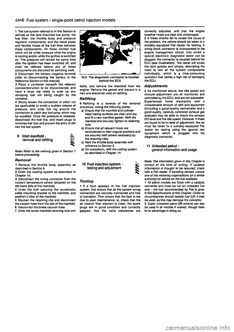
10.2 The diagnostic connector la located behind the ECU bolts, and remove (he manifold from the engine. Remove the gasket and discard It; a new one should be used on refitting.
Refitting 8 Refitting is a reverse of the removal procedure, noting the following points: a) Ensure that the manifold and cylinder head mating surfaces are clean and dry, and fit a nev/ manifold gasket. Refit the manifold and securely tighten Its retaining nuts. b) Ensure that all relevant hoses are reconnected fo their original positions and are securely held (where necessary) by the retaining clips. c) Refit the throttle body assembly with reference to Section S. d) On completion, refill the cooling system as described In Chapter 1A.
correctly adjusted, and that the engine breather hoses are clear and undamaged. 2 If these checks fall to reveal the cause of the problem, the vehicle should be taken to a suitably-equipped Fiat dealer for testing. A wiring block connector Is Incorporated In the engine management circuit, into which a special electronic diagnostic tester can be plugged; the connector is situated behind the ECU (see Illustration). The tester will locate the fault quickly and simply, alleviating the need to test all the system components Individually, which is a time-consuming operation that carries a high risk of damaging the ECU.
Adjustments 3 As mentioned above, the idle speed and mixture adjustment are all monitored and controlled by the ECU, and are not adjustable Experienced home mechanics with a considerable amount of skill and equipment (including a good-quality tachometer and a good-quality, carefully calibrated exhaust gas analyser) may be able to check the exhaust CO level and ihe idle speed. However, If thes* are found lo be in need of adjustment, the car must be taken to a suitably-equipped Flat dealer for testing using the special test equipment which is plugged into the diagnostic connector.
11 Unleaded petrol -general Information and usage
10 Fuel injection system - & testing and adjustment S
Testing 1 If a fault appears in the fuel injection system, first ensure that all the system winng connectors are securely connected and free of corrosion. Then ensure that the fault Is not due to poor maintenance; ie, check that the air cleanor fitter element is clean, the spark plugs are In good condition and correctly gapped, that tho valve clearances are
Note: The information given in this Chapter
is
correct at the time of writing. If updated Information is thought to be required, check with a Fiat dealer. If travelling abroad, consult one of the motonng organisations (or a similar authority) for advice on the fuel available. 1 All petrol models are fitted with a catalytic converter and must be run on unleaded fuel only - the fuel recommended by Flat is given In the Specifications of this Chapter. Under no circumstances should leaded fuei (UK 4-slar) be used, as this may damage the converter. 2 Super unleaded petrol (98 octane) can also be used in all models if wished, though there is no advantage in doing so.
Page 127 of 225
4B*1
Chapter 4 Part B:
Fuel system - multi-point petrol injection models
Contents
Accelerator cable - removal, refitting and adjustment 4 Air cleaner and Inlet system • removal and refitting 2 Air cleaner filter element renewal See Chapter 1A Engine management system components (1242 cc, 8-valve engines) -removal and refitting 5 Engine management system components (1242 cc, 16-valve engines) - removal and refitting 6 Fuel filter renewal See Chapter 1A Fuel Injection system - depressurisation 9
Degrees of difficulty
Fuel injection system - testing and adjustment 11 Fuel pump and fuel gauge sender unit - removal and refitting 7 Fuel tank - removal and refitting 8 General Information and precautions 1 Idle speed and mixture adjustment See Chapter 1A Inlet air temperature regulator - removal and refitting 3 Inlet manifold - removal and refitting 10 Unleaded petrol • general Information and usage 12
Easy, suitable
for ^
novice with
Ittie experience ^
Fairly
easy,
suitable Jk for beginner
with
® someexperiencs ^
FaMycSffiait, J^ suitable
for
competent ^
DIY mechanic
^
Difficult
suitable
for experienced BY SJ mechanic ^
Very difficult,
^
suitable
for expert
DIY
jR or professional ^
Specifications
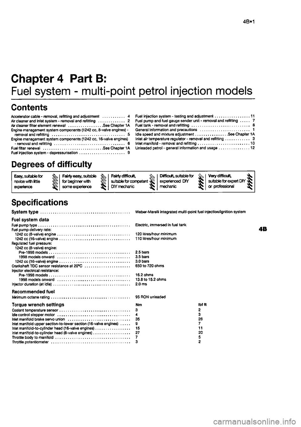
System type
Fuel system data Fuel pump type Fuel pump delivery rate: 1242 cc (8-vatve) engine 1242 cc (16-valve) engine Regulated fuel pressure: 1242 cc (8-vaive) engine: Pre-1998 models 1998 models onward 1242 cc (16*valve) engine Crankshaft TDC sensor resistance al 20°C Injector electrical resistance: Pre-1998 models 1998 models onward Injector duration (at Idle)
Recommended fuel Minimum octane rating
Torque wrench settings Coolant temperature sensor
Idle
control stepper motor Inlet manifold brake servo union Inlet manifold upper section-to-lower section (16-valve engines) Inlet manifold-to-cylinder head (16-valve engines) Inlet manlfold-to-cylinder head (8-valve engines) Throttle body to manifold Throttle potentiometer
Weber-Marelli integrated multi-point fuel injection/ignition system
Electric, immersed In fuel tank
120 Hires/hour minimum 110 litres/hour minimum
2.5 bars 3.5 bars 3.0 bars 650 to 720 ohms
16.2 ohms 13.8 to 15.2 ohms 2.0 ms
95 RON unleaded
Nm Ibfft a 2 4 3 35 26 9 7 15 11 27 20 7 5 3 2
Page 128 of 225
4A*2 Fuel system -
single-point
petrol Injection models
1 General information and precautions
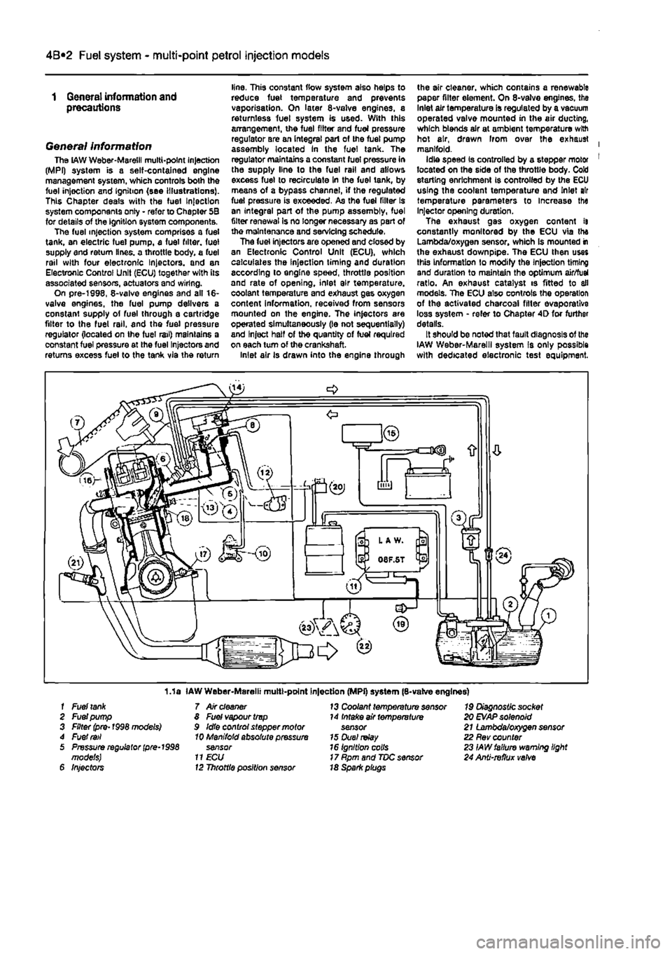
General information The
LAW
Weber-Maretil multi-point Injection (MPI) system is a self-contained engine management system, which controls both the fuel injoction and Ignition (see Illustrations). This Chapter deals with the fuel Injection system components only - refer to Chapter 5B for details of the ignition system components. The fuel injection system comprises a fuel tank, an electric fuel pump, a fuel filter, fuel supply end return lines, a throttle body, a fuel rail with four electronic Injectors, and an Electronic Control Unit (ECU) together with its associated sensors, actuators and wiring. On pre-1998, 8-valve engines and all 16-valve engines, the fuel pump delivers a constant supply of fuel through a cartridge filter to the fuel rail, and the fuel pressure regulator (located on Ihe fuel rail) maintains a constant fuel pressure at the fuel Injectors and returns excess fuel to the tank via the return
line, This constant flow system also helps to reduce fuel temperature and prevents vaporisation. On later 8-valve engines, a returnless fuel system is used. With this arrangement, the fuel filter and fuel pressure regulator are an integral part of the fuel pump assembly located In the fuel tank. The regulator maintains a constant fuel pressure in the supply line lo the fuel rail and allows excess fuel to recirculate in the fuel tank, by means of a bypass channel, if the regulated fuel pressure is exceeded. As the fuel filler Is an integral part of the pump assembly, fuel filter renewal Is no longer necessary as part of the maintenance and servicing schedule. The fuel injectors are opened and closed by an Electronic Control Unit (ECU), which calculates the Injection timing and duration according to engine speed, throttle position and rate of opening, inlet air temperature, coolant temperature and exhaust gas oxygen content information, received from sensors mounted on the engine. The injectors are operated simultaneously (le not sequentially) and Inject half of the quantity of fuel required on each turn of the crankshaft. Inlet air Is drawn into the engine through
the air cleaner, which contains a renewable paper filter element. On 8-valve engines, the Inlet air temperature is regulated by a vacuum operated valve mounted in the air ducting, which blends air at ambient temperature with hot air, drawn Irom over the exhaust | manifold. Idle speed Is controlled by a stepper motor 1 located on the side of the throttle body. Cold storting enrichment is controlled by the ECU using the coolant temperature and Inlet air temperature parameters to Increase the Injector opening duration. The exhaust gas oxygen content it constantly monitored by the ECU via the Lambda/oxygen sensor, whioh Is mounted in the exhaust downpipe. The ECU then uses this Information to modify the Injection timing and duration to maintain the optimum air/fuel ratio. An exhaust catalyst is fitted to all models. The ECU also controls the operation of the activated charcoal filler evaporative loss system - refer to Chapter 4D for further details. It should be noted that fault diagnosis of the IAW Weber-Marelll system Is only possible with dedicated electronic test equipment.
1.1a IAW Weber-Marelii multt-point Injection (MPi) system (8-valve engines) f Fuel
tank
7 Air
cleaner
13 Coolant temperature sensor 19 Diagnostic socket 2 Fuel pump 8 Fuel vapour trvp 14 Intake air temperature 20
EVAP
solenoid 3 Filter (pre-1998 models) 9 Idle control stepper motor sensor 21 Lambda/oxygen sensor 4 Fuel
rail
10 Manifold absolute pressure 15 Duel
relay
22 Rev counter 5 Pressure regulator
(pre-1998
sensor 16 Ignition colls 23 IAW failure warning light models)
11 ECU
17 Rpm and TDC sensor 24 Anti-refhjx
valve
6 Injectors 12 Throttle position sensor 18 Spark piugs
Page 129 of 225
4A*2 Fuel system -
single-point
petrol Injection models
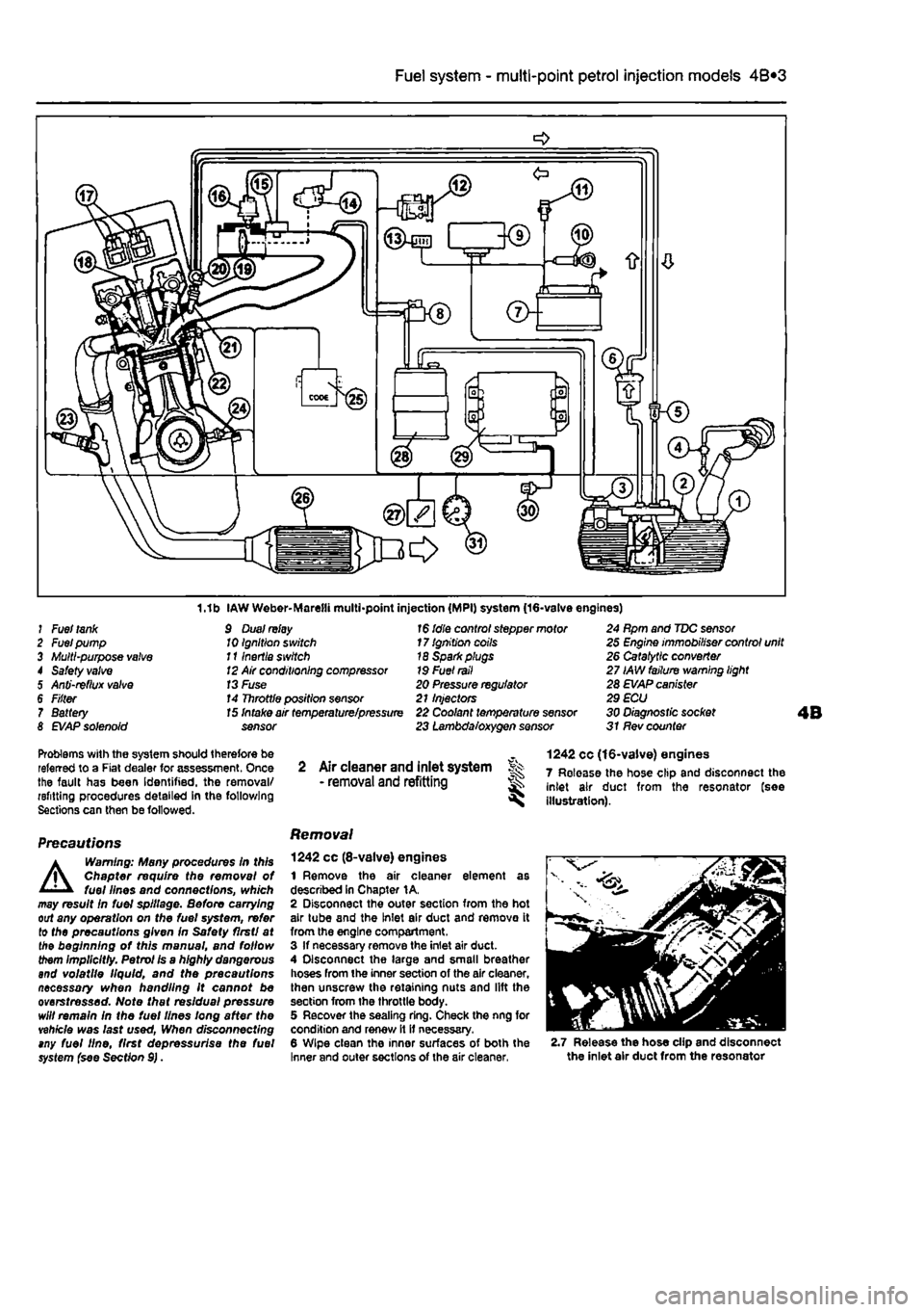
1.1b IAW Weber-Marelli multi-point injection (MPI) system (16-valve engines) J Fuel
tank
2 Fuel pump 3 Multi-purpose
valve
4 Safety
valve
5 Anti-reflux
valve
6 F/fter 7 Battery 8
EVAP
solenoid
9 Dual
relay
10 Ignition switch 111nertia switch
12
Air conditioning compressor
13
Fuse 14 Throttle position sensor
1$
idle control stepper motor 17 Ignition coils 18 Sparkplugs 19 Fuel
rail
20 Pressure regulator 21 Injectors
15
Intake air temperature/pressure 22 Coolant temperature sensor sensor 23 Lambda/oxygen sensor
24 Rpm and TDC sensor 25 Engine immobiliser control unit 26 Catalytic converter 27 IAW failure warning light 28 EVAP canister 29 ECU 30 Diagnostic socket 31 Rev counter
Problems with the system should therefore be referred to a Fiat dealer for assessment. Once the fault has been Identified, the removal/ refitting procedures detailed in the following Sections can then be followed.
Precautions
A
Warning: Many procedures In this Chapter require the removal of fuel lines and connections, which may result In fuel spillage. Before carrying out any operation on the fuel system, refer to the precautions given In Safety flrstl at the beginning of this manual, and follow them implicitly. Petrol Is a highly dangerous and volatile liquid, and the precautions necessary when handling it cannot be overstressed. Note that residual pressure will remain in the fuel lines long after the vehicle was last used, When disconnecting tny fuel line, first depressurise the fuel system {see Section 9).
2 Air cleaner and inlet system Sk - removal
and
refitting ^
Removal
1242 cc (8-valve) engines 1 Remove the air cleaner element as described In Chapter 1A. 2 Disconnect the outer section from the hot air tube and the Inlet air duct and remove it from the engine compartment. 3 If necessary remove the inlet air duct. 4 Disconnect the large and small breather hoses from the inner section of the air cleaner, then unscrew the retaining nuts and lift the section from the throttle body. 5 Recover the sealing ring. Check the nng for condition and renew it it necessary. 6 Wipe clean the inner surfaces of both the Inner and outer sections of the air cleaner,
1242 cc (16-valve) engines 7 Release the hose clip and disconnect the inlet air duct from the resonator (see illustration).
2.7 Release the hose clip and disconnect the inlet air duct from the resonator
Page 134 of 225
4A*2 Fuel system -
single-point
petrol Injection models
Refitting 37 Refitting Is a reversal of removal making sure that the wiring connector is securely reconnected.
Inertia safety switch 36 Refer to Chapter 4A, Fuel injection system relays Removal 39 The fuel injection system twin relay Is located under a plastic cover on the engine compartment bulkhead. 40 The main purpose of the relay Is to supply current to the fuel pump, ignition coils, oxygen sensor, Injectors and EVAP solenoid. The relay is controlled by the ignition switch. A15 amp fuse, protecting ihe fuel pump, oxygen sensor and EVAP solenoid is located adjacent to the relay. 41 Remove the cover and pull the relay directfy from Its socket. Refitting 42 Refitting is a reversal of removal.
7 Fuel pump and fuel gauge sender unit - JK removal
and
refitting ^
Removal Note: Refer fo (he warning given in Section 1 before proceeding. 1 Disconnect the battery negative terminal (refer to Disconnecting the battery In the Reference Section of this manual). 2 Depreasurise the fuel system as described in Section 9. 3 Remove the rear soat as described In Chapter 11. Prise the fuel pump access cover out of the floor panel to gain access to the pump unit. On later models, undo the three retaining screws to release the cover. 4 Disconnect the wiring connector. 5 Bearing In mind the warning given In Section t, disconnect Ihe fuel supply and, where applicable, the return lines from tho pump unit by pressing the tabs. Plug the ends of the lines or cover them with adhesive tape. 6 Using a suitable tool, unscrew the large ring nut and carefully withdraw the fuel pump/fuel tank sender unit assembly from the fuel tank, along with its sealing rtng. 7 If necessary, the unit can be dismantled and the pump and sender unit separated. If this is (he case, carefully note the correct fitted positions of all components while dismantling the unit, and use these notes on reassembly to ensure that all items are correctly fitted.
Refitting 8 Refitting is a reversal of the removal procedure using a new sealing ring. Prior to refitting the access cover, reconnect the battery, then start the engine and check the fuel line unlon(s) (or signs of i
Fuel
tank -removal and refitting
Refer to Chapter 4A.
9 Fuel injection system -depressurisatton
Note: Refer to the warning given In Section 1 before proceeding.
A
Warning: The following procedure will merely relieve the pressure In the fuel system • remember that fuel will still be present In the system components and take precautions accord-ingly before disconnecting any of them. 1 The fuel system referred to in this Section is defined as the lank-mounted fuel pump, tha fuel filter, the fuel rail, the fuel injectors, and the metal pipes and flexible hoses of the fuel lines between these components. All these contain fuel which will be under pressure while the engine Is running and/or while the Ignition is switched on. The pressure will remain for some time after the Ignition has been switched off. and must be relieved before any of these components are disturbed for servicing work. 2 Disconnect the battery negative terminal (refer to Disconnecting the battery In the Reference Section of this manual). 3 Have a large rag ready to cover the union to be disconnected and, if possible, place a con-tainer beneath the relevant connection/union. 4 Slowly loosen the connection or union nut (as applicable) to avoid a sudden release of pressure, and ensure that the rag is wrapped around the connection to catch any fuef spray which may be expelled. Once the pressure is released, disconnect the fuel line, and Insert plugs to minimise fuel loss and prevent the entry of dirt Into the fuel system. Note that on later models, quick-release fuel couplings are used on many of the fuel line connections. To release these couplings, depress the two clips on the side of the coupling while keeping the fuel line pushed In. With the clips depressed, slowly withdraw the fuel line from the coupling allowing the fuel pressure to release, then withdraw the fuel line fully.
10 Inlet manifold-removal
and
refitting
Note: Refer fo the warning given in Section 1 before proceeding.
1242 cc (8-valve) engines
Removal 1 Remove ihe throttle body assembly as described in Section 5.
2 Remove the fuel rail and injectors at described in Section 5. 3 Drain the cooling system ss described n Chapter 1A. 4 Disconnect the wiring connector from ih* coolant temperature sensor (situated on it* left-hand side of the manifold). 5 Undo the bolt securing the accelerator cable mounting bracket to the manifold, am position it clear of the manifold. 6 Slacken the retaining clip and disconnect the coolant hose from the rear of the mandold 7 Disconnect the brake vacuum hose, 6 Undo the seven manifold retaining nuisw bolts, and remove the manifold from tta engine. Remove the gasket and discard tti new one should be used on refitting. Refitting
9 Refitting is a reverse of the removjf procedure, noting the following points: a) Ensure that the manifold and cylinder lim mating surfaces are dean and
dry.
and fill new manifold gasket. Refit the
manifold
and securely tighten Its retaining
nuts.
b) Ensure all relevant hoses are recorwscfed fo their original positions and are
sacurtfy
held (Where necessary; by the
retaining
clips. c) Refit the fuel rail and injectors, and
the
throttle body assembly with
reference to
Sect/on 5. d) On completion, refill the cooling
system
as described in Chapter 1A. 1242 cc (16-valve) engines
Removal 10 Disconnect the battery negative ternnncf (refer to Disconnecting the battery in ths Reference Section of this manual). 11 Remove the resonator, air cleaner and inlet air duct as described In Section 2. 12 Drain the cooling system as described r, Chapter 1A. 13 Free the accelerator inner cable from IN throttle cam. remove the outer cable spring dip. then pull the outer cable out from itt mounting bracket rubber grommet. 14 From the side of the throttle boOf, disconnect the wiring connectors from the throttle potentiometer and the Idle contrd stepper motor. Disconnect the coolant temperature sensor wiring connector located in the Inlet manilold below the throttie bodr, and disconnect the brake servo vacuum hose. 15 Disconnect Ihe wiring connectors for the fuel in|ector harness and the Intake a* temperature/pressure sensor, thtn disconnect the fuel pressure regulator vacuum hose and the EVAP purge valve
hose
(see illustration). 16 Undo Ihe two bolts securing the plastic Inlet manifold upper section to the lower section. Release the spark plug HT lead from the location groove in the manifold upper section, then lift Ihe upper section, complete with throttle body, off the engine. Recover
the
O-rings from the manifold pons.
Page 137 of 225
Fuel system - diesel models 4C*3
Torque wrench settings Nm Ibfft Fuel injection pump roar bracket .. . 29 21 Fuel Injection pump .... 25 18 Fuel Injectors 41 Fuel pipe union nuts .... 30 22 Inlet manifold .... 24 18 Lower oil tiller mounting and injection pump mounting nut ..... .... 71 S2 Turbocnarger to exhaust manifold .... <10 30 Upper Dtl filter mounting end injection pump mounting nut 98 72
1 General information and precautions
General information The fuel system consists of a rear-mounted fust tank, a fuel filter with integral water separator, a fuel injection pump, in|eciors and associated components. A turbocharger is fitted to TDS, TD and TDSX models. Fuel Is drawn from the fuel tank to the fuel Injection pump by a vane-type transfer pump Incorporated in the fuel injection pump. Before reaching tho pump, the fuel passes through a fuel filter, where foreign matter and water aro removed. Excess fuel lubricates the moving components of the pump, and Is then returned to the tank. On turbo models with the Bosch fuel Injection systom, an eiectncally operated heater is incorporated In the fuel filter housing. The fuel injection pump is driven at half-crankshaft speed by the timing belt. The nigh pressure required to inject tho fuel into the compressed air in the swirl chambers Is achlovod by a cam plate acting on a single piston on the Bosch pumo, or by two opposed pistons forced together by rollers running in a cam ring on the Lucas (CAV) pump. Tlie fuel passes through acentral rotor with a single outlet drilling which aligns With ports leading to the Injector pipes. Fuel metering is controlled by a centrifugal governor, which reacts to accelerator pedal
position end engine speed. The governor is linked lo a metering valve, which increases or decreases the amount of fuel delivered at each pumping stroke. On turbocharged models, a separate device also Increases luel delivery with increasing boost pressure. Basic injection timing is determined when the pump is fitted. When the engine is running, it Is varied automatically to suit the prevailing engine speed by a mechanism which turns the cam plate or ring, Tho four fuel injectors proouco a homogeneous spray of fuel Into the swirl chambers located In the cylinder head. The Injectors are calibrated to open end close at critical pressures lo provide efficient and even combustion. Each injector needle is lubricated by fuel, which accumulates In the spring chamber and is channelled to the injection pump return hose by loak-off pipes Bosch or Lucas fuel system components mBy be fitted, depending on the model. Components from the latter manufacturer are marked either CAV. Roto-dlesel or Con-diesel. depending on their date and place of manufacture. With the exception of the fuel filter assembly, replacement components must be of tho same make as those originally fitted. Cold starting is assisted by preheater or glow plugs fitted to each swirl chamber. On the Bosch injection pump, an automatic cold Injection advance device operated through a thermal switch, advances the injection timing by Increasing the fuel pressure. The device operates at coolant temperatures below 55° C,
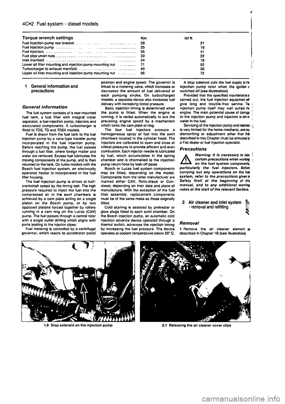
A stop solenoid cuts the fuel supply to V* Injection pump rotor when the ignition i switched off (see illustration) Provided that the specified maintenance* earned out. the fuel injection equipment #» give long and trouble-free service, ft* j injection pump itself may well outlast tlx ' engine, The main potential cause of damage j to the injection pump and injectors is dirt e water in the fuel. 1 Servicing of the injection pump and injectwi: j, is very limited for tho home mechanic, antf dismantling or adjustment other than thtf described In this Chapter must be entrusted to ' a Rat dealer or fuel Injection specialist.
Precautions
A
Warning: It Is necessary to takt I certain precautions when woriong , on the fuel system component^ particularly the fuel Injectors. Befon carrying out any operations on tho fuel system, refer to the precautions given* Safety first! at the beginning of Mis manual, and to any additional wamlrq notes at the start of the relevant
Sections.
2 Air cleaner and inlet system ^ • removal and refitting S
Removal 1 Remove the air cleaner element u described In Chapter 1B (see illustration).
1.9 Stop solenoid on the injection pump 2.1 Releasing the air cleaner cover clips
Page 145 of 225
4D*2 Exhaust and emission control systems
2.2 Charcoal canister location behind tho right-hand headlight
conditions, via a plunger valve, The system is controlled electronically by means of an emissions system control unit. Evaporative emission control • petrol models To minimise the escape of unburned hydrocarbons Into the atmosphere, an evaporallve loss emission control system is fitted to petrol models, The fuel tank filler cap Is sealed and a charcoal canister is mounted underneath the right-hand headlamp to collect the petrol vapours released from the fuel contained In the fuel tank. It stores them until they can be drawn from the canister (under the control of the fuel Injection/ignition system ECU) via the purge valve into the Inlet tract, where they are then burned by the engine during normal combustion. To ensure thai the engine runs correctly when it is cold and/or idling and to protect the catalytic converter from the effects of an over-rich mixture, the purge control valve is not opened by the ECU until the engine has warmed up, and the engine is under load; the valve solenoid is then modulated on and off to allow the stored vapour to pass into the inlet tract.
Exhaust systems The exhaust system comprises the exhaust manifold, an exhaust downpipe, • catalytic convorter, an intermediate pipe with silencer, and a tailpipe with silencer, On turbo diesel models the turbocharger is fitted between ihe exhaust manifold and the downpipe.
5.5a On 16-valve engines, undo the bolts and remove the manifold heat shield...
2 Evaporative loss emission ^ control system - information and component renewal ^
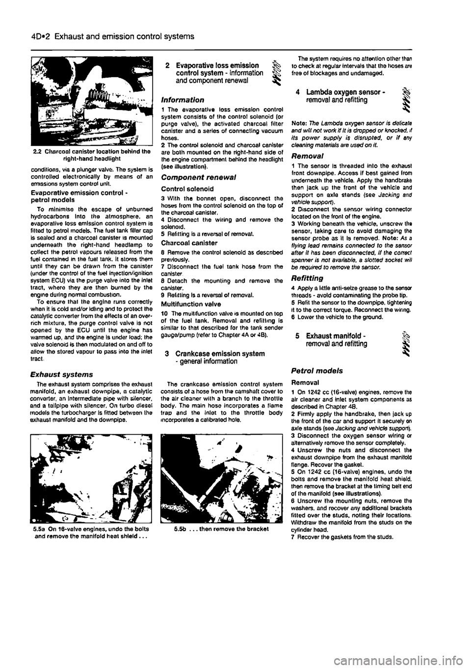
Information 1 The evaporative loss omission control system consists of the control solenoid (or purge valve), the activated charcoal filter canister and a series of connecting vacuum hoses. 2 The control solenoid and charcoal canister are both mounted on the right-hand side of the engine compartment behind the headlight (see illustration).
Component renewal
Control solenoid 3 With the bonnet open, disconnect the hoses from the control solenoid on the top of the charcoal canister. 4 Disconnect the wiring and remove the solenoid. 5 Refitting is a reversal of removal. Charcoal canister 6 Remove Ihe control solenoid as desenbed previously. 7 Disconnect Ihe fuel tonk hose from the canister 8 Detach the mounting and remove the canister. 9 Refitting Is a reversal of removal. Multifunction valve 10 The multifunction valve >s mounted on top of the luel tank. Removal and refitting is similar to that described for the tank sender gauge/pump (refer to Chapter 4A or 4B).
3 Crankcase emission system - general information
The crankcase emission control system consists of a hose from the camshaft cover to the air cloanor with a branch to Ihe throttle body. The main hose Incorporates a flame trap and the Inlet to the throttle body incorporates a calibrated hole.
5.5b ... then remove the bracket
The system requires no attention other than to check at regular intervals that tho hoses are free of blockages and undamaged.
4 Lambda oxygen sensor -removal and refitting &
Note: 7?5e Lambda oxygen sensor is doiicata and will not work if it is dropped or knocked, it its power supply is disrupted, or if any cleaning materials are used on it.
Removal 1 The sensor Is threaded Into the exhaust front downpipe. Access if best gained Irom underneath the vehicle. Apply the handbrake then )ack up the front of the vehicle and support on axle stands (see Jacking and vehicle support). 2 Disconnect the sensor wiring connector located on the front of the engine. 3 Working beneath the vehicle, unscrew the sensor, taking care to avoid damaging the sensor probe as it Is removed- Note: As a flying lead remains connected to the sensor after it has been disconnected, if the correct spanner is not available, a slotted socket
will
be required to remove the sensor.
Refitting A Apply a little anti-selze grease to (he sensor threads • avoid contaminating the probe tip. 5 Refit the sensor to the downpipe. tightening it to the correct torque. Reconnect the wiring. 6 Lower the vohicle to the ground.
5 Exhaust manifold - % removal and refitting jk
Petrol models
Removal 1 On 1242 cc (16-valve) engines, remove tho air cleaner and inlet system components as described in Chapter 48. 2 Firmly apply the handbrake, then jock up the front of the car and support It securely on axle stands (see Jacking and vehicle support). 3 Disconnect the oxygen sensor wiring or alternatively romovo Ihe sensor completely. 4 Unscrew the nuts and disconnect the exhaust downpipo from Ihe exhaust manifold flange. Recover the gasket. 5 On 1242 cc (16-valve) engines, undo the bolts and remove the manifold heat shield, then remove the bracket at the timing belt end of the manifold (seo Illustrations). 6 Unscrew the mounting nuts, remove the washers, and recover any additional brackets fitted over the studs, noting their locations. Withdraw the manifold from the studs on the cylinder head. 7 Recover the gaskets from Ihe studs.
Page 146 of 225
4D*3 Exhaust and emission control systems
Refitting 8 Refitting is a reversal of the removal pro-cedure but fit new gaskets. Tighten the nuts lo the specified torque.
Diesel models Note: On diesel models the inlet and exhaust
manifolds
are located on the rear of the engine
end
share the same securing nuts and gasket. Removal 8 Remove the inlet manifold as described In Part
C
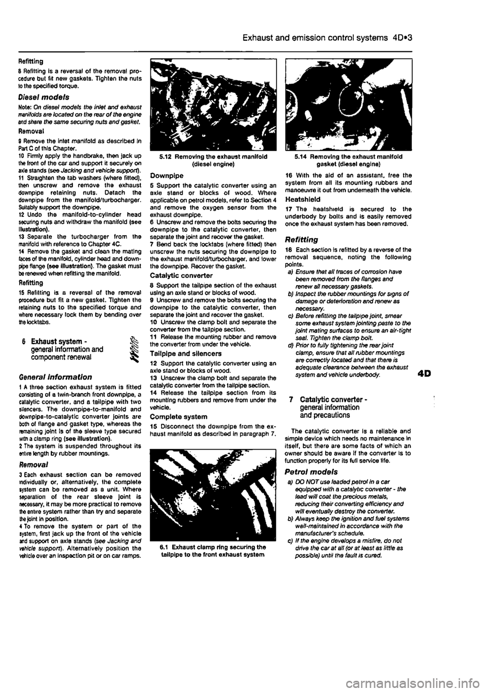
of this Chapter. 10 Firmly apply the handbrake, then jack up lite front of tho car and support it securely on axle stands (see Jacking and vehicle support). 11 Straighten the tab washers (where fitted), then unscrew and remove the exhaust downpipe retaining nuts. Detach the downpipe from the manifold/turbocharger. Suitably support the downpipe. 12 Undo the manifold-to-cylinder head securing nuts and withdraw the manifold (see Illustration). 13 Separate the turbocharger from the manifold with reference to Chapter 4C. 14 Remove the gasket and clean the mating
(aces
of the manifold, cylinder head and down-pipe flange (see illustration). The gasket must
be
renewed when refitting the manifold, Refitting
15 Refitting is a reversal of the removal procedure but fit a new gasket. Tighten the retaining nuts to the specified torque and where necessary lock them by bending over
the
tocktabs.
6 Exhaust system - % general information and ^ component renewal
Genera/ Information 1 A three section exhaust system is fitted consisting of a twin-branch front downpipe, a catalytic converter, and a tailpipe with two silencers. The downpipe-to-manifold and downpipe-to-catalytic converter joints are both of flange and gasket type, whereas the remaining joint Is of the sleeve type secured
witn
a clamp ring (see illustration). 2 The system is suspended throughout its entire length by rubber mountings.
Removal 3 Each exhaust section can be removed individually or, alternatively, the complete system can be removed as a unit. Where separation of the rear sleeve Joint is necessary, it may be more practical to remove
the
entire system rather than try and separate
the Joint
In position. 4 To remove the system or part of the system, first jack up the front of the vehicle and support on axle stands (see Jacking and nhlcle support), Alternatively position the
vehicle
over an inspection pit or on car ramps.
5.12 Removing the exhaust manifold (diesel engine) Downpipe 5 Support the catalytic converter using an axle stand or blocks of wood. Where applicable on petrol models, refer to Section 4 and remove the oxygen sensor from the exhaust downpipe. 6 Unscrew and remove the bolts securing the downpipe to tha catalytic converter, then separate the joint and recover the gasket. 7 Bend back the locktabs (where fitted) then unscrew the nuts securing the downpipe to the exhaust manifold/turbocharger. and lower the downpipe, Recover the gasket. Catalytic converter
8 Support the tailpipe section of the exhaust using an axle stand or blocks of wood. 9 Unscrew and remove the bolts securing the downpipe to the catalytic converter, then separate the joint and recover the gasket. 10 Unscrew the clamp bolt and separate the converter from the tailpipe section. 11 Release the mounting rubber and remove the converter from under the vehicle. Tailpipe and silencers 12 Support the catalytic converter using an axle stand or blocks of wood. 13 Unscrew the clamp bolt and separate the catalytic converter from the tailpipe section. 14 Release the tailpipe section from its mounting rubbers and remove from under the vehicle. Complete system 15 Disconnect the downpipe from the ex-haust manifold as described in paragraph 7.
6.1 Exhaust clamp ring securing the tailpipe to the front exhaust system
5.14 Removing the oxhaust manifold gasket (diesel engine) 16 With the aid of an assistant, free the system from all its mounting rubbers and manoeuvre it out from underneath the vehicle. Heatshield 17 The heatshield is secured to the underbody by bolts and Is easily removed once the exhaust system has been removed.
Refitting 18 Each section is refitted by a reverse of the removal sequence, noting the following points. a) Ensure that all traces of corrosion have been removed from the flanges and renew ail necessary gaskets. b) Inspect the rubber mountings for signs of damage or deterioru tion and renew
as
necessary. c) Before refitting the tailpipe joint, smear some exhaust system jointing paste to the joint mating surfaces to ensure an air-tight seal. Tighten the clamp bolt. d) Prior to fully tightening the rear joint damp, ensure that all rubber mountings are correctly /ocafed and that there is adequate clearance between the exhaust system and vehicle underbody.
7 Catalytic converter -general information and precautions
The catalytic converter is a reliable and simple device which needs no maintenance In itself, but there are some facts of which an owner should be aware if the converter is to function properly for its full service life.
Petrol models a) DO NOT use leaded petrot In a car equipped with a catalytic converter - Ihe lead will coat the precious metals, redudng their converting efficiency
and
will eventually destroy the converter. b) Always keep the ignition and fuel systems well-maintained in accordance with the manufacturer's schedule. c) If the engine develops a misfire, do not drive the car at all (or at least as little
as
possible) until the fault is cured.
Page 147 of 225
4D*4 Exhaust and emission control systems
d) DO NOT push- or tow-start the car - this will soak the catalytic converter
in
unbumed fuel, causing It to overheat when the engine does start. e) DO NOT switch off the ignition at high engine speeds. f) DO NOT use fuel or engine oil additives -these may contain substances harmful to the catalytic converter. g) DO NOT continue to use the car If
the
engine bums oil to the extent of leaving
a
visible trail of blue smoke.
h) Remember that the catalytic converter operates at very high temperatures. DO NOT, therefore, park the car in dry undergrowth, over long grass or piles of deed leaves after a long run. I) Remember that the catalytic converter is FRAGILE - do not strike it with tools during servicing work, j} In some cases a sulphurous smell
pike
that of rotten eggs) may be noticed from the exhaust. This Is common to many catalytic converter-equipped cars and
once the car has covered a few
thousand
miles tha problem should
disappear,
k)
The
catalytic converter, used on a
weW*
maintained and well-driven car, should las for between
SO
000 and
100
000
miles-If
the converter is no longer effective It
must
be renewed.
Diesel models Refer to the information given in parts i,
g, h
and I of the petrol models information given above.
Page 149 of 225
5A«2 Starting and charging systems
1 General information and precautions
General information The engine electrical system consists mainly of the charging and starting systems. Because of their engine-related functions, these components are covered separately from the body electrical devices such as the Ilght3, Instalments, etc (which are covered In Chapter 12). On petrol engine models refer to Part B for information on the ignition system, and on diesel models refer to Part C for information on the preheating system. The electncal system Is of 12-volt negative earth type. The battery fitted as original equipment is of maintenance* free (sealed for life} type and Is charged by the alternator, which is belt-driven from the crankshaft pulley. If a non-original battery is fitted It may be of standard or low maintenance type. The starter motor is of the pre-engaged type Incorporating an integral solenoid. On starting, the solenoid moves the drive pinion into engagement with the flywheel ring gear before the starter motor is energised. Once the engine has started, a one-way clutch prevents the motor armature being driven by the engine until the pinion disengages from the flywheel.
Precautions Further details of the various systems are given In the relevant Sections of this Chapter. While some repair procedures are given, the usual course of action is to renew the component concerned. The owner whose interest extends beyond mere component renewal should obtain a copy of the Automobile Electrical & Electronic Systems Manual, available from the publishers of this manual It Is necessary to take extra care when working on the electrical system to avoid damage to semiconductor devices (diodes and transistors), and to avoid the risk of personal injury. In addition to the precautions given in Safety first! at the beginning of this manual, observe the following when working on the system: Always remove rings, watches, etc before working on the electrical system. Even with the battery disconnected, capacitlve discharge could occur If a component's live terminal is earthed through a metal object. This could cause a shock or nasty bum. Do not reverse the battery connections. Components such as the alternator, electronic control units, or any other components having semi-conductor circuitry could be irreparably damaged. If the engine is being started using jump leads and a slave battery, connect the batteries positive-to-posibve and negative-to-
negative (see Jump starting). This also applies when connecting a battery charger but In this case both of the battery terminals should first be disconnected. Never disconnect the battery terminals, the alternator, any electrical wiring or any test Instalments when the engine Is running. Do not allow the engine to turn the alter-nator when the alternator Is not connected. Never test for alternator output by flashing the output lead to earth. Never use an ohmmeter ot the type Incorporating a hand-cranked generator for circuit or continuity testing. Always ensure that the battery negative lead is disconnected when working on the electrical system. Before using electric-arc welding equipment on the car, disconnect the battery, alternator and components such as the fuel Injection/ignition electronic control unit to protect them from the risk of damage. Several systems fitted to the vehicle require battery power to be available at all times, either to ensure their continued operation (such as the clock) or to maintain control unit memories or security codos which would be wiped if the battery were to be disconnected. To ensure that there are no unforeseen consequences of this action. Refer to Disconnecting the battery In the Reference Section of this manual for further Information.
2 Battery- % testing and charging
Standard and tow maintenance battery - testing 1 If the vehicle covers a small annual mileage, it is worthwhile checking the specific gravity of the electrolyte every three months to determine the state of charge of the battery. Use a hydrometer to make the check and compare the results with the following table, Note that the specific gravity readings assume an electrolyte temperature of 15*C (60'F); for every 10*C (18°f) below 158C (60aF) subtract 0.007, For every 108C (16'F) above 15"C (60'F) add 0.007. Ambient temperature Above 26"C Below 25DC Charged 1,210 to 1£30 1,270 to 1.290 70% charged 1.170to1.l90 1.230to1.250 Discharged 1.050toJ.070 1.110 to 1.130 2 If the battery condition is suspect, first check the specific gravity of electrolyte In each cell. A variation of 0.040 or more between any cells indicates loss of electrolyte or deterioration of the internal plates. 3 If the specific gravity variation is 0.040 or more, the battery should be renewed. If the cell variation Is satisfactory but the battery is discharged, it should be charged as described later in this Section.
Maintenance-free battery -testing 4 In cases where a sealed tor life maintenance-free battery is fitted, topplng-up and testing of the electrolyte in each cell Is not possible. The condition of the battery can therefore only be tested using a battery condition Indicator or a voltmeter. 5 Certain models may be fitted with a maintenance-free battery with a built-in charge condition Indicator. The indicator Is located in the top of the battery casing, and indicates the condition of the battery from its colour. If the Indicator shows green, then the battery is In a good state of charge. If the Indicator turns darker, eventually to black, then the battery requires charging, as described later in this Section. If Ihe indicator shows clear/yellow, then the electrolyte level in Ihe battery is too low to allow further use, and tho battery should be renewed. Do not attempt to charge, load or Jump start a battery when the indicator shows dear/yellow. 6 If testing the battery using a voltmeter, connect the voltmeter across the battery and compare the result with those given In the Specifications under 'charge condition'. The test is only accurate if the battery has not been subjected to any kind of charge for the previous six hours. If this is not the esse, switch on the headlights for 30 seconds, then wait four to five minutes baforo testing the battery after switching off the headlights. All other electrical circuits must be switched off, so check that the doors and tailgate are fully shut when making the test, 7 It the voltage reading Is less than 12.2 voHs, then the battery Is discharged, whilst a reading of 12.2 to 12.4 volts indicates 8 partially discharged condition. 6 If the battery Is to be charged, remove It from the vehicle (Section 3) and charge it as described later In this Section.
Standard and low maintenance battery - charging Note: The following is Intended as a guide only. Always refer to the manufacturer's recommendations (often printed on a label attached to the battery) before charging a battery. 9 Charge the battery at a rate of 3.5 to 4 amps and continue to charge the battery at this rate until no further rise In specific gravity Is noted over a four hour period. 10 Alternatively, a trickle charger charging at the rate of 1.5 amps can safely be used overnight. 11 Specially rapid boost charges which are claimed to restore the power of the battery in t to 2 hours are not recommended, as they can cause serious damage to the battery plates through overheating, 12 While charging the battery, note that the temperature of the electrolyte should never exceed 37.8*C(100°F),