Timing FIAT PUNTO 1999 176 / 1.G Repair Manual
[x] Cancel search | Manufacturer: FIAT, Model Year: 1999, Model line: PUNTO, Model: FIAT PUNTO 1999 176 / 1.GPages: 225, PDF Size: 18.54 MB
Page 145 of 225

4D*2 Exhaust and emission control systems
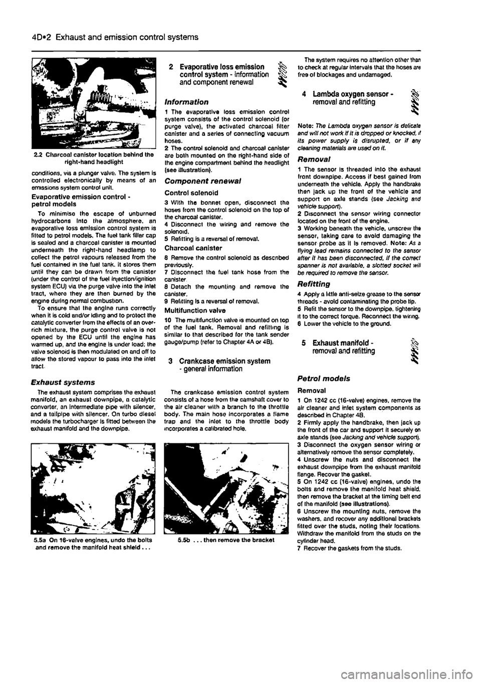
2.2 Charcoal canister location behind tho right-hand headlight
conditions, via a plunger valve, The system is controlled electronically by means of an emissions system control unit. Evaporative emission control • petrol models To minimise the escape of unburned hydrocarbons Into the atmosphere, an evaporallve loss emission control system is fitted to petrol models, The fuel tank filler cap Is sealed and a charcoal canister is mounted underneath the right-hand headlamp to collect the petrol vapours released from the fuel contained In the fuel tank. It stores them until they can be drawn from the canister (under the control of the fuel Injection/ignition system ECU) via the purge valve into the Inlet tract, where they are then burned by the engine during normal combustion. To ensure thai the engine runs correctly when it is cold and/or idling and to protect the catalytic converter from the effects of an over-rich mixture, the purge control valve is not opened by the ECU until the engine has warmed up, and the engine is under load; the valve solenoid is then modulated on and off to allow the stored vapour to pass into the inlet tract.
Exhaust systems The exhaust system comprises the exhaust manifold, an exhaust downpipe, • catalytic convorter, an intermediate pipe with silencer, and a tailpipe with silencer, On turbo diesel models the turbocharger is fitted between ihe exhaust manifold and the downpipe.
5.5a On 16-valve engines, undo the bolts and remove the manifold heat shield...
2 Evaporative loss emission ^ control system - information and component renewal ^
Information 1 The evaporative loss omission control system consists of the control solenoid (or purge valve), the activated charcoal filter canister and a series of connecting vacuum hoses. 2 The control solenoid and charcoal canister are both mounted on the right-hand side of the engine compartment behind the headlight (see illustration).
Component renewal
Control solenoid 3 With the bonnet open, disconnect the hoses from the control solenoid on the top of the charcoal canister. 4 Disconnect the wiring and remove the solenoid. 5 Refitting is a reversal of removal. Charcoal canister 6 Remove Ihe control solenoid as desenbed previously. 7 Disconnect Ihe fuel tonk hose from the canister 8 Detach the mounting and remove the canister. 9 Refitting Is a reversal of removal. Multifunction valve 10 The multifunction valve >s mounted on top of the luel tank. Removal and refitting is similar to that described for the tank sender gauge/pump (refer to Chapter 4A or 4B).
3 Crankcase emission system - general information
The crankcase emission control system consists of a hose from the camshaft cover to the air cloanor with a branch to Ihe throttle body. The main hose Incorporates a flame trap and the Inlet to the throttle body incorporates a calibrated hole.
5.5b ... then remove the bracket
The system requires no attention other than to check at regular intervals that tho hoses are free of blockages and undamaged.
4 Lambda oxygen sensor -removal and refitting &
Note: 7?5e Lambda oxygen sensor is doiicata and will not work if it is dropped or knocked, it its power supply is disrupted, or if any cleaning materials are used on it.
Removal 1 The sensor Is threaded Into the exhaust front downpipe. Access if best gained Irom underneath the vehicle. Apply the handbrake then )ack up the front of the vehicle and support on axle stands (see Jacking and vehicle support). 2 Disconnect the sensor wiring connector located on the front of the engine. 3 Working beneath the vehicle, unscrew the sensor, taking care to avoid damaging the sensor probe as it Is removed- Note: As a flying lead remains connected to the sensor after it has been disconnected, if the correct spanner is not available, a slotted socket
will
be required to remove the sensor.
Refitting A Apply a little anti-selze grease to (he sensor threads • avoid contaminating the probe tip. 5 Refit the sensor to the downpipe. tightening it to the correct torque. Reconnect the wiring. 6 Lower the vohicle to the ground.
5 Exhaust manifold - % removal and refitting jk
Petrol models
Removal 1 On 1242 cc (16-valve) engines, remove tho air cleaner and inlet system components as described in Chapter 48. 2 Firmly apply the handbrake, then jock up the front of the car and support It securely on axle stands (see Jacking and vehicle support). 3 Disconnect the oxygen sensor wiring or alternatively romovo Ihe sensor completely. 4 Unscrew the nuts and disconnect the exhaust downpipo from Ihe exhaust manifold flange. Recover the gasket. 5 On 1242 cc (16-valve) engines, undo the bolts and remove the manifold heat shield, then remove the bracket at the timing belt end of the manifold (seo Illustrations). 6 Unscrew the mounting nuts, remove the washers, and recover any additional brackets fitted over the studs, noting their locations. Withdraw the manifold from the studs on the cylinder head. 7 Recover the gaskets from Ihe studs.
Page 150 of 225

5A«2 Starting and charging systems
Maintenance-free battery -charging Note: The following is intended as a guide only. Always refer to the manufacturer's recommendations (often printed on a label attached to the battery) before charging a battery. 13 This battery type takes considerably longer lo fully recharge than the standard type, the time taken being dependent on the extent of discharge, but it can take anything
up
to three days. 14 A constant voltage type charger is required, tooe set, when connected, to 13.9 to 14.9 votts wth a charger current below 25 amps. Using
mis
method, the battery should be usable within three hours, giving a voltage reading of 12.5 vofts. but this Is for a partially discharged battery and, as mentioned, full charging can
take
considerably longer. 15 If Ihe battery is to be charged from a fully discharged state {condition reading loss lhan 12.2 volts), have it recharged by your FIAT dealer or local automotive electrician, as Ihe charge rate is higher and constant super-vision during charging Is necessary.
3 Battery -removal and refitting
Note: Refer to Disconnecting the battery in ifte Reference Section of this manual before proceeding.
Removal 1 Slacken the clamp bolts and disconnect the ctamp from the battery negative (earth) terminal. 2 Remove the insulation cover (where fitted)
and
disconnect the positive terminal lead(s) in
Die same
way. 3 At the base of the battery, unscrew the bolt from the battery holding clamp plate and remove the clamp plate (see Illustration). A Remove the battery from Ihe engine compartment. 5 II necessary the mounting tray may be removed by unscrewing the bolts. On diesel models it will be necessary to remove the relay guard bolts as well.
Refitting 6 Refitting is a reversal of removal but make sure that the positive terminal is connected first followed by the negative terminal.
4 Alternator/charging system - >%•> testing in vehicle
Note: Refer to the warnings given in Safety first! and in Section 1 of this Chapter before starting work. 1 If the ignition warning light fails to Illuminate when the ignition is switched on, first check the alternator wiring connections for security. If satisfactory, check that the warning light bulb has not blown, and that the bulbholder is secure in its location in the instrument panel. If the light still fails to illuminate, check the continuity of the warning light feed wire from the alternator to the bulbholder. If all is satisfactory, the alternator is at fault and should be renewed or taken to an auto-electrician for testing and repair. 2 If the ignition warning light Illuminates when the engine Is running, stop the engine and check that the drivebelt is correctly tensioned (see Chapter 1A or 18) and that the alternator connections are secure. If all is so far satisfactory, have the alternator checked by an auto-electrician. 3 If the alternator output is suspect even though the warning light functions correctly, the regulated voltage may be checked as follows. 4 Connect a voltmeter across the battery terminals and start the engine. 5 Increase the engine speed until the voltmeter reading remains steady; the reading should be approximately 12 to 13 volts, and no more than 14 volts. 6 Switch on as many electrical accessories (eg. the headlights, heated rear window and heater blower) as possible, and check that the alternator maintains the regulated voltage at around 13 to 14 volts. 7 If ihe regulated voltage is not as stated, the fault may be due to worn brushes, weak brush springs, e faulty voltage regulator, a faulty diode, a severed phase winding or worn or damaged slip rings. The alternator should be renewed or taken to an auto-electrician for testing and repair.
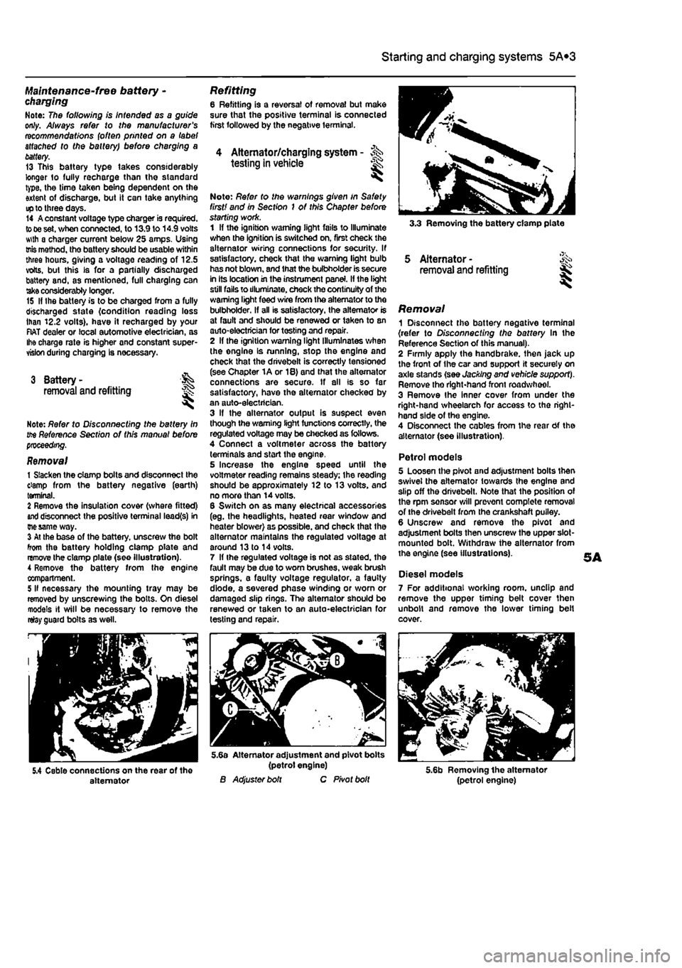
3.3 Removing the battery clamp plate
5 Alternator -removal and refitting
Removal 1 Disconnect the battery negative terminal {refer to Disconnecting the battery In the Reference Section of this manual). 2 Firmly apply the handbrake, then jack up the front of the car and support it securely on axle stands (see Jacking and vehicle support). Remove tho right-hand front roadwheel. 3 Remove Ihe Inner cover from under the right-hand wheelarch for access to tho right-hand side of the engine. 4 Disconnect the cables from the rear Of the alternator (see illustration).
Petrol models 5 Loosen the pivot and adjustment bolts then swivel the alternator towards the engine and slip off the drivebelt. Note that the position of the rpm sensor will prevent complete removal of the drivebelt from the crankshaft puiley. 6 Unscrew and remove the pivot and adjustment bolts then unscrew the upper slot-mounted bolt. Withdraw the alternator from the engine (see illustrations).
Diesel models 7 For additional working room, unclip and remove the upper timing belt cover then unbolt and remove the lower timing belt cover.
5.4 Cable connections on the rear of the alternator
5.6a Alternator adjustment and pivot bolts (petrol engine) B Adjuster bolt C Pivot bolt 5.6b Removing the alternator (petrol engine)
Page 153 of 225

5B*1
Chapters PartB:
Ignition system - petrol models
Contents
General information 1 Ignition system - testing 2 Ignriton HT coil - removal, testing and refitting 3 Ignition timing - checking and adjustment 4 Igrrtion system - check See Chapter 1A Spark plugs - renewal See Chapter 1A
Degrees of difficulty
Easy,
suitable for Falrty easy, sulabte Fafety difficult, suitable for competent Difficult, suitable for Very difficult, ^ novice with littie
1
for beginner with Fafety difficult, suitable for competent experienced DIY suitable for expert DIY or professional ^ expenence 1 some experience DIY mechanic mechanic *
suitable for expert DIY or professional ^
Specifications
General System type
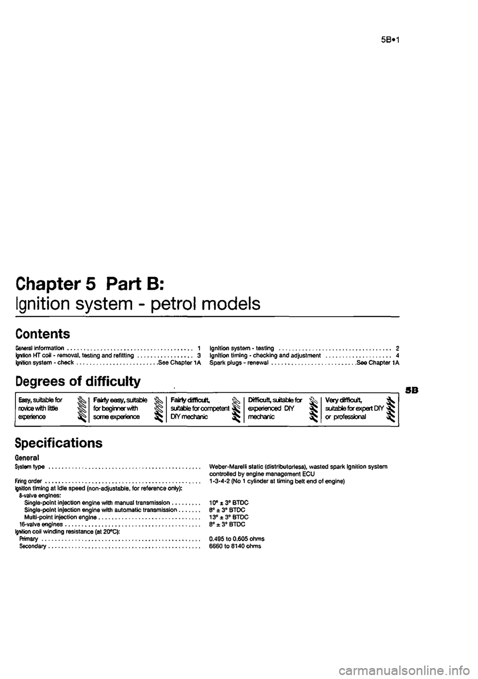
firing order Ignition timing at Idle speed (non-adjustable, for reference onlyy. 6-valve engines: Single-point injection engine with manual transmission .... Single-point injection engine with automatic transmission.. Multi-point injection engine 16-valve engines
Ignition
coil winding resistance (at 20°C): Primary Secondary
Weber-Marelli static (distributorless), wasted spark Ignition system controlled by engine management ECU
1
-3-4-2 (No 1 cylinder at timing belt end of engine)
10® ± 3° BTDC 6° ± 3° STDC 13° ±3° BTDC 8° x 3° BTDC
0.495 to 0.605 ohms 6660 to 8140 Ohms
Page 155 of 225

Ignition system - petrol models 5B®3
Chapter 1A tor further information. Also check tnat tha accelerator cable is correctly adjusted
as
described in the relevant part of Chapter 4. If the engine is running very roughly, check the compression pressures and the valve clearances as descnbed In the relevant parts of Chapters 1 and 2. 2
H
these checks fall to reveal the cause of the problem, the vehicle should be taken to a suitably equipped Fiat dealer for testing. A wiring block connector Is Incorporated in the engine management circuit Into which a special electronic diagnostic tester can be plugged. The tester will locate the fault quickly and simply alleviating the need to test all the system components Individually which is a time consuming operation that carries a high risk of damaging the ECU. 3 The only Ignition system checks which can
oe
earned out by the home mechanic are those cescribed in Chapter 1A, relating to the spark plugs, and the ignition coll test descnbed In this Chapter. If necessary, the system wiring and wiring connectors can oe checked as descnbed in Chapter 12, Section 2, ensuring that the ECU wiring connector(s) have first
been
disconnected.
3 Ignition HT coil - ^ removal, testing and refitting
Removal 1 On 6-valve engines, unscrew the boll and remove the plastic cover from the left-hand
end
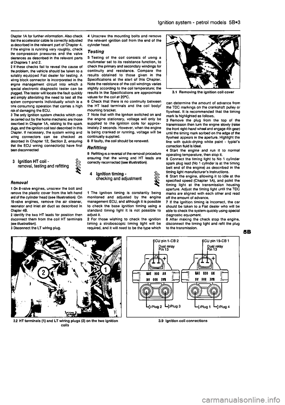
of the cylinder head (see Illustration). On 15-valve engines, remove the air cleaner, resonator and Inlet air duct as described in Chapter 4B. 2 Identify the two HT leads for position then disconnect them from the coil HT terminals jsee illustration). 3 Disconnect the LT wiring plug.
4 Unscrew the mounting bolts and remove the relevant ignition coil from the end of the cylinder head,
Testing 5 Testing of the coil consists of using a multimeter set to its resistance function, to check the primary and secondary windings for continuity and resistance. Compare the results obtained to those given In the Specifications at the start of this Chapter. Note the resistance of the coil windings varies slightly according to the coil temperature; the results In the Specifications are approximate values for the coil at 20°C. 6 Check that there is no continuity between the HT lead terminals and the coil body/ mourning bracket. 7 Note that with the ignition switched on and the engine stationary, voltage will only be supplied to the ignition cotls for approx-imately 2 seconds. However, when tho engine is being cranked or running, voltage will be continually supplied. 8 If faulty, the coil should be renewed.
Refitting 9 Refitting ts a reversal of the removal procedure ensuring that the winng and HT leads are correctly reconnected (see illustration).
4 ignition timing • checking and adjustment
1 The Ignition timing is constantly being monitored and adjusted by the engine management ECU, and although it is possible to check the base ignition liming using a standard timing light It is not possible to adjust it. 2 For those wishing to check the ignition timing a stroboscope timing light will be required, and it will need to be the type which
3.1 Removing the ignition coll cover
can determine the amount of advance from the TDC markings on the crankshaft pulley or flywheel. It Is recommended that the timing mark is highlighted as follows. 3 Remove the plug from the top of the transmission then turn tho engine slowly (raise the front right-hand wheel and engage 4th gear) until the timing mark scribed on the edge of the flywheel appears in the aperture. Highlight the line with quick-drying white paint - typist's correction fluid is ideal. 4 Start the engine and run It to normal operating temperature, then stop it. 5 Connect the timing light to No 1 cylinder spark plug lead (No 1 cylinder Is at the timing belt end of the engine) as described in the timing light manufacturer's Instructions. 6 Start the engine, allowing it to idle at the specified speed (Chapter 1A), and point the timing light at the transmission housing aperture. Adjust the timing light until the TDC marks are aligned with each other and read off the amount of advance. 7 If the ignition timing is incorrect, the car should be taken to a Fiat dealer who will be able to check the system quickly using special diagnostic equipment. 8 After making the check stop the engine, disconnect the timing light and refit the plug to the transmission.
3.2 HT terminals (1) and LT wiring plugs (2) on the two ignition colls 3.9 Ignition colt connections