Timing FIAT PUNTO 1999 176 / 1.G Owner's Guide
[x] Cancel search | Manufacturer: FIAT, Model Year: 1999, Model line: PUNTO, Model: FIAT PUNTO 1999 176 / 1.GPages: 225, PDF Size: 18.54 MB
Page 73 of 225
2C«1
Chapter 2 PartC:
Diesel engine in-car repair procedures
Contents
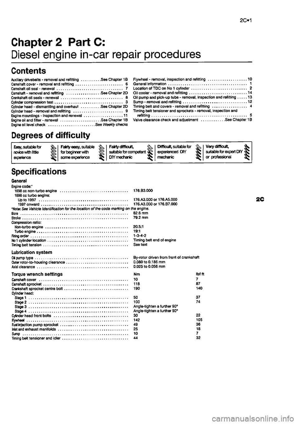
Auxiliary drivebelts - removal and refitting See Chapter 1B Camshaft cover - removal and refitting 6 Camshaft oil seal - renewal 7 Camshaft - removal and refitting See Chapter 20 Crankshaft oil seats - renewal 8 Cylinder compression test « 3 Cylinder head - dismantling and overhaul See Chapter 20 Cylinder head - removal and refitting 9 Engine mountings - inspection and renewal 11 Engine oil and fitter - renewal See Chapter 18 Engine oil level check See Weekly checks
Degrees of difficulty
Flywheel * removal, inspection and refitting 10 General information 1 Location of TDC on No 1 cylinder 2 Oil cooler - removal and refitting 14 Oil pump and pick-up tube • removal, Inspection and refitting 13 Sump • removal and refitting 12 Timing belt and covers • removal and refitting 4 Timing belt tensioner and sprockets - removal, Inspection and refitting 5 Valve clearance check and adjustment See Chapter 1B
Easy,
suitable for novice
with Irttle
|| experience g^
FaMy
eesy,
suitable ^
forbeglnnerwilti
some experience ^
Falrtydfficult, ^ suitable
for
competent DIYmechanic ^
Difficult, suitable
for & experienced DIY mechanic ^
Very
difficult,
^ suitable
for
expert
DfY
jR or professional ^
Specifications
General Engine code:' 1698 cc non-turbo engine 176.B3.000 1698 cc turbo engine: Up to 1997 t76.A3.00aor176.A5.000 1997 onward 176.A3.000or176.B7.000 •Note: See Vehicle Identification for the location of the code marking on the engine. Bore 82.6 mm Stroke 79.2 mm Compression ratio: Non-turbo engine 20.5:1 Turbo engine 19:1 Firing order 1-3-4-2
No 1
cylinder location Timing belt end of engine Titling belt tension See text
Lubrication system Oi pump type By-rotor driven from front of crankshaft Outer rotor-to-houslng clearance 0.080 to 0.186 mm Axial clearance 0.025 to 0.056 mm
Torque wrench settings Nm ibf ft Camshaft cover 10 7 Camshaft sprocket 11B 87 Crankshaft sprocket centre bolt 190 140 Cylinder head: Stage 1 50 37 Stage 2 100 74 StageS Angle-tighten a furtfier 90" Stage 4 Angle-tighten a further 90° CySnder head front bolts 30 22 Flywheel 142 105
Fuel
injection pump sprocket 49 36 Inlet and exhaust manifolds 25 18 Sump 10 7 Timing belt tensioner and idler 44 32
Page 74 of 225
2C*2 Diesel engine in-car repair procedures
1 General information
Using this Chapter Chapter 2 is divided Into four Parts; A. 8, C and 0. Repair operations that cart be carried out with the engine in the vehicle are described In Part A, SOHC (B-valve) petrol engines. Part B, DOHC (16-valve) petrol engines and Part C. diesel engines, Part D covers the removal of the engine/transmission as a unit, and describes the engine dismantling and overhaul procedures. In Parts A. 8 and C. the assumption Is made that the engine is installed in Ihe vehicle, with all anciliaries connected If the engine has been removed for overhaul, the preliminary dismantling information which precedes each operation may be ignored.
Engine description Both normally aspirated (non-turbo) and turbocharged diesel engines are fitted to the Punto range. The engines together with their codes are given in the Specifications at the start of lhis Chapter. The engines are water-cooled, single-overhead camshaft. In-line lour cylinder units with cast-iron cylinder blocks and aluminium-alloy cylinder heads. The engine is mounted transversely at the front of the vehicle, with the transmission bolted to the left-hand side of the engine. The cylinder head carries the camshaft which is driven by a toothed timing belt. It also houses the inlet and exhaust valves which are closed by single coll valve springs and run in valve guides pressed into the cylinder head. The valves are operated by cam followers fitted over each valve, and the clearances are adjusted by shims positioned between the followers and the camshaft lobes. The camshaft is supported by four bearings • the end bearings are machined in the cylinder head and the remaining bearings have caps bolted to the cylinder head. The cylinder head contains integral oiiways which supply and lubricate the camshaft and followers and it also Incorporates renewable swirl chambers. The crankshaft Is supported by five main bearings, and endfloat Is controlled by a thrust bearing fitted on the rear main bearing. All diesel engines are fitted with a brake servo vacuum pump dnven from the left-hBnd end of the camshaft. Engine coolant is circulated by a pump, driven by the auxiliary drivebeit. For details of the cooling system refer to Chapter 3. Lubricant is circulated under pressure by a pump, driven from the front of the crankshaft. Oil is drawn from the sump through a strainer, and then forced through an externally-mounted, replaceable screw-on filter. From there, it is distributed to the cylinder head.
where il lubncates the camshaft journals and followers, and also to the crankcase, where it lubricates the main bearings, connecting rod big- and small-ends, gudgeon pins and cylinder bores. Oil jets are fitted to the base of each cylinder bore - these spray oil onto the underside of the pistons, lo Improve cooling. An oil cooler is also fitted to reduce the temp-erature of oil before it re-enters the engine.
Repair operations possible with the engine in the car The following work can be carried out with the engine in the can a) Compression pressure - testing b) Auxiliary drivebeit - removal and refitting (refer to Chapter rej c) Valve clearances • checking and adjustment (refer to Chapter 1B) d) Camshaft cover - removal and refitting e) Tim/ng belt and covers • removal and refitting 0 Timing belt tensioner and sprockets -removal and refitting g) Cylinder head - removal and refitting' h) Camshaft and cam followers - removal end refitting' I) Camshaft oil seal - renewal j) Crankshaft oil seals - renewal k) Flywheel • removal, inspection and refitting I) Engine mountings - inspection and renewal m)Sump • removal and refitting n) Oil pump and pick-up tube assembly -removal, inspection and refitting 'Cylinder head dismantling procedures are detalfed In Chapter 2D, with details of camshaft and cam follower removal. Note: It ts possible to remove the pistons and connecting rods (after removing the cylinder nead and sump) without removing the engine. However, this is not recommended. Work of this nature is more easily and thoroughly completed with the engine on tho bench as described in Chapter 2D.
2 Location of
TDC
on ^ No
1
cylinder ||
General information 1 The camshaft and fuel Injection pump are driven by the crankshaft, by means of sprockets and a timing belt. All three sprockets rotate in phase with each other and this provides the correct valve and injection pump timing as the engine rotates. When the timing bell is removed during servicing or repair, it is possible for the camshaft, injection pump and crankshaft to rotate independently of each other and the correct timing Is then lost.
2 It
Location of TDC on cylinder No
1
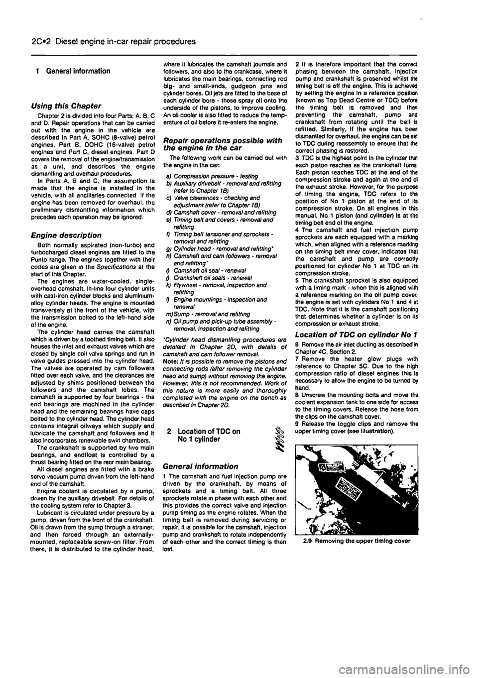
6 Remove the air inlet ducting as described ft Chapter 4C, Section 2. 7 Remove the heater glow plugs with reference to Chapter 5C. Due to the high compression ratio of diesel engines this Is necessary to allow the engine to be turned by hand. 8 Unscrew the mounting bolts and move the coolant expansion tank to one side for access to the timing covers. Release the hose from the clips on Ihe camshaft cover. 9 Release the toggle clips and remove the upper timing cover (see illustration),
2.9 Removing the upper timing cover
Page 75 of 225
Diesel engine in-car repair procedures
2C*11
10 firmly apply the handbrake, then jack up
Ihe
front of the car and support it securely on
arte stands
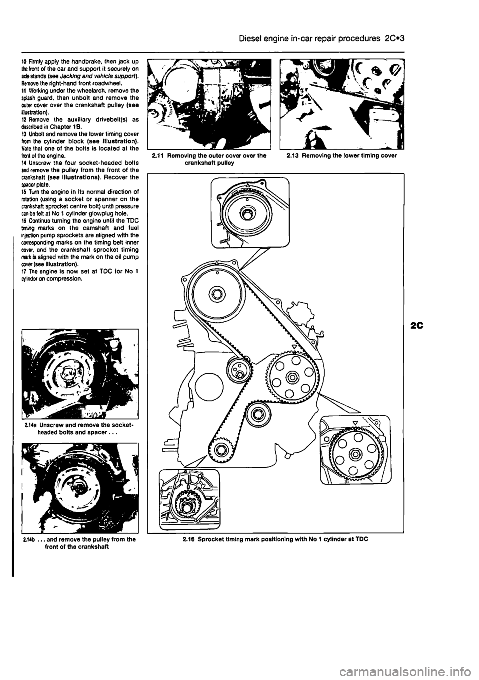
(see Jacking and vehicle support). Remove the right-hand front roadwheel. 11 Working under the wheelarch. remove the splash guard, than unbolt and remove the outer cover over the crankshaft pulley (see ilustratlon). 12 Remove the auxiliary drivebelt(s) as described in Chapter 18. 13 Unbolt and remove the lower timing cover from the cylinder block (see Illustration). Note that one of the bolts is located at the
Iron!
of the engine. 14 Unscrew the four socket-headed bolts
and
remove the pulley from the front of the crankshaft (see illustrations). Recover the {pacer plate. 15 Turn the engine in its normal direction of rotation (using a socket or spanner on the crankshaft sprocket centre bolt) until pressure
can be
felt at No 1 cylinder gtowplug hole. 16 Continue turning the engine until the TDC timing marks on the camshaft and fuel injection pump sprockets are aligned with the corresponding marks on the timing belt inner cover, and the crankshaft sprocket timing
mark
is aligned with the mark on the oil pump cover (see illustration). 17 Tne engine is now set at TDC tor No 1 e>llnder on compression.
114a Unscrew and remove the socket-headed bolts and spacer...
2.11 Removing the outer cover over the 2.13 Removing the lower timing cover crankshaft pulley
2.14b ... and remove the pulley from the 2.18 Sprocket timing mark positioning with No 1 cylinder et TDC front of the crankshaft
Page 76 of 225
2C*2 Diesel engine in-car repair procedures
4.4a Unbolt the engine oil dipstick tube...
3 Cylinder compression test
Note: A compression tester specifically designed for diesef engines must be used for this test. 1 When engine performance Is down, or if misfiring occurs, a compression test can provide diagnostic clues as to the engine's condition, If the lest is performed regularly, it can give warning of trouble before any other symptoms become apparent. 2 A compression tester specifically Intended for diesel engines must be used, because of the higher pressures involved. The Ie6ter is connected to an adapler which screws Into the glow plug or injector hole. It is unlikely to be worthwhile buying such a tester for occasional use. but it may be possible to borrow or hire one • if not. have the test performed by a garage. 3 Unless specific instructions to the contrary are supplied with the tester, observe the following points: 9) The battery must bo in a good state of charge, the air titter must be clean, end the engine should be at normal operating temperature. b) AH the in/actors or glow plugs should be removed before starting the lest. If removing the injectors, also remove the flame shield washers, otherwise they may be blown out. c) The stop solenoid must be disconnected.
4.4b ... and remove it from the rubber grommet in the oil pump housing
fo prevent the engine from running or fuel from being discharged. 4 There is no need to hold the accelerator pedal down during the test, because the diesel engine air inlet is not throttled. 5 The cause of poor compression Is less easy to establish on a diesel engine than on a petrol one. The effect of introducing oil into the cylinders (wet testing) Is not conclusive, because there is a risk that the oil will sit in the recess on the piston crown, instead of passing to the rings. However the following can be used as a rough guide to diagnosis. 6 All cylinders should produce very similar pressures; a difference of more than 5 bars between any two cylinders Indicates the existence of a fault. Note that the compression should build up quickly In a healthy engine; low compression on the first stroke, followed by gradually-increasing pressure on successive strokes, indicates worn piston rings. A low compression reading on the first stroke, which does not build up during successive strokes, indicates leaking valves or a blown head gasket (a cracked hoad could also be the cause). 7 A low reading from two adjacent cylinders Is almost certainly due to the head gasket having blown between them: the presence of coolant In the engine oil will confirm this,
Leakdown test 8 A leakdown test measures the rate at which compressed air fed into the cylinder Is lost. It is an alternative to a compression test, and in many ways it is better, since the escaping air provides easy identification of where pressure loss is occurring (piston rings, valves or head gasket). 9 The equipment needed for leakdown testing is unlikely to be available to the home mechanic. If poor compression Is suspected, have the test performed by a suitably-equipped garage.
4 Timing belt and covers -removal
and
refitting
Note: Fiat specify the use of a spec/a/ timing belt tension measuring tool to correctly set the timing belt tension. If access to this equipment cannot be obtained, an approximate setting can be achieved using the method described below. If the method described is used, the tension must be checked using the special tool at the earliest possible opportunity. Do not drive the vehicle over large distances, or use high engine speeds, until the belt fens/on rs known to be correct. Refer to a Fiat dealer for advice.
General Information 1 The function of the timing belt is to drive the camshaft and fuel injection pump. Should the belt slip or break in service, the valve timing will be disturbed and piston-to-valve contact
will occur, resulting In serious engine damage. 2 The timing bolt should be renewed at the specified intervals (see Chapter 1B), or earlier If It is contaminated with oil. or If It is at al noisy In operation (a scraping noise due to uneven wear),
Removal 3 Set the engine at TDC on No 1 cylinder
as
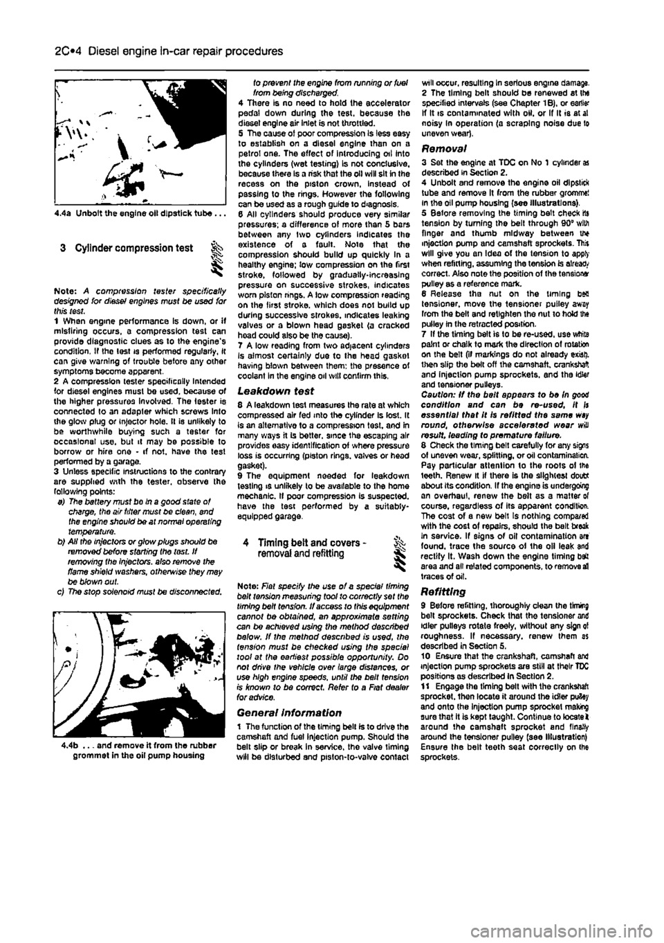
described in Section 2. 4 Unbolt and remove tho engine oil dipstick tube and remove It from the rubber gromme! in the oil pump housing (see illustrations), 5 Before removing the timing belt check rts tension by turning the belt through 90" with finger and thumb midway between u* injection pump and camshaft sprockets. This will give you an Idea of the tension to apply when refitting, assuming the tension is already correct. Also note the position of the tensions pulley as a reference mark. 6 Release tho nut on the timing bea tensioner, move the tensioner pulley away from the belt and retlghten the nut to hold the pulley in the retracted position. 7 If the timing belt is to be re-used, use white paint or chalk to mark the direction of rotation on the belt (if markings do not already exist), then slip the belt off the camshaft, crankshaft and injection pump sprockets, and the idler and tensioner pulleys. Caution: If the belt appears to be In good condition and can be re-used, it fs essential that It Is refitted the same
wsy
round, otherwise accelerated wear will result, leading fo premature failure. 8 Check the timing belt carefully for any signs of uneven wear, splitting, or oil contamination. Pay particular attention to the roots of the teeth. Renew it if there is the slightest doutt about its condition. If the engine is undergoing an overhaul, renew the belt as a matter of course, regardless of its apparent conditio*. The cost of a new belt Is nothing compa/ed with the cost of repairs, should the belt freak in service. If signs of oil contamination art found, trace the source of the oil leak and rectify It. Wash down the engine timing baft area and all related components, to remove
sd
traces of oil.
Refitting 9 Before refitting, thoroughly clean the tknmg belt sprockets. Check that the tensioner and idler pulleys rotate freely, without any sign ol roughness. If necessary, renew them as described in Section 5. 10 Ensure that the crankshaft, camshaft and injection pump sprockets are still at their TDC positions as described In Section 2. 11 Engage the timing belt with the crankshaft sprocket, then locate it around the idler pufiey and onto the Injection pump sprocket making sure that it is kept taught. Continue to locate! around the camshaft sprocket and finally around Ihe tensioner pulley (see Illustration) Ensure the belt teeth seat correctly on Ihe sprockets.
Page 77 of 225
Diesel engine in-car repair procedures
2C*11
C«/ffor>: Where applicable observe the drnctbn of rotation markings on the belt. 12 Tension the timing belt by turning the eccentrically-mounted tensioner clockwise: two ities are provided in the side of the tensioner ftb for this purpose - a pair of sturdy right-ircfed circiip pliers can be used to do this or iftemaiively two bolts and a long screwdriver
may be
used. Fiat use a special tensioner tool
located in
the hotos - this consists of a calibrated rod
and
weight. The weight is positioned 60 mm tog the rod to provide the correct tension to the belt, then the tensioner nul is tightened. Tgttn tho tensioner nut to the specified torque
(see
illustrations) 13
If the
tensioner tool Is not available, test the wsicn by grasping the timing belt between the li^er and thumb midway between the camshaft and injection pump pulleys, and Using il through 90" (see paragraph S).
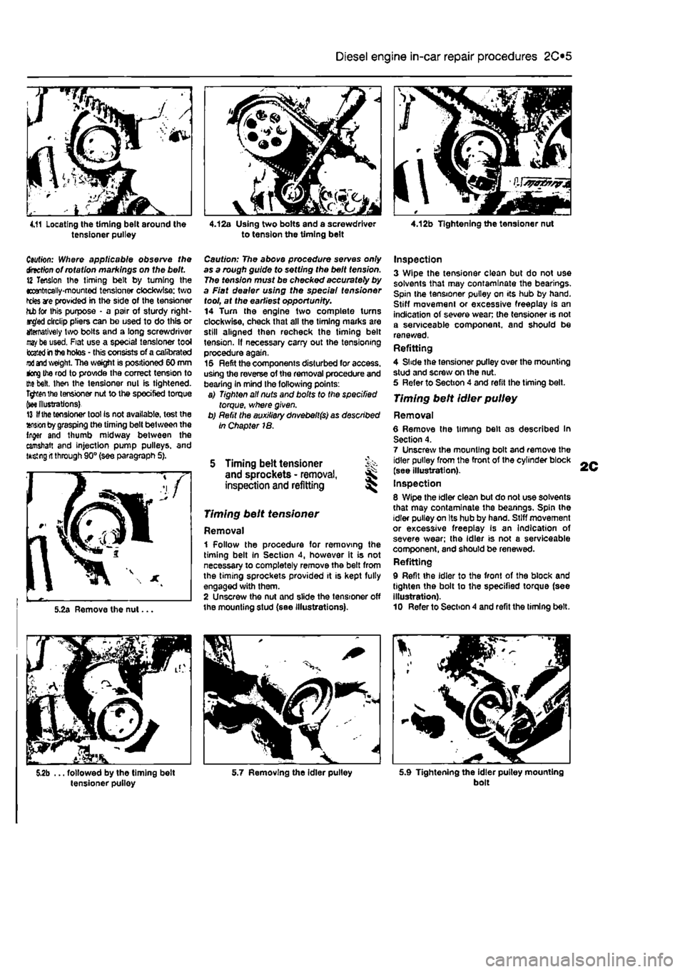
Caution: The above procedure serves only as a rough guide to setting the belt tension. The tension must be checked accurately by a Fiat dealer using the spec/a/ fens/oner tool, at the earliest opportunity. 14 Tum the engine two complete turns clockwise, check that all the timing marks are still aligned then recheck the timing belt tension. If necessary carry out the tensioning procedure again, 15 Refit the components disturbed for access, using the reverse of the removal procedure and bearing In mind the following points: a) Tighten all nuts and bolts to the specified torque, where given. b) Refit the auxiliary dnvebelt(s) as described in Chapter 18.
5 Timing belt tensioner ^ and sprockets - removal, ^ inspection and refitting ^
1 Follow the procedure for removing the timing belt In Section 4, however it is not necessary to completely remove the belt from the timing sprockets provided it is kept fully engaged with them. 2 Unscrew the nut and slide the tensioner off the mounting stud (see illustrations).
Inspection 3 Wipe the tensioner clean but do not use solvents that may contaminate the bearings. Spin the tensioner pulley on its hub by hand. Stiff movemeni or excessive freeplay Is an Indication of severe wean the tensioner is not a serviceable component, and should be renewed, Refitting 4 Slide the tensioner pulley over the mounting stud and screw on the nut. 5 Refer to Section 4 and refit the timing belt.
Timing belt idler pulley
Removal 6 Remove Ihe timing belt as described In Section 4. 7 Unscrew the mounting bolt and remove the idler pulley from the front of the cylinder block (see illustration). Inspection 8 Wipe the idler clean but do not use solvents that may contaminate the bearings. Spin the idler pulley on Its hub by hand. Stiff movement or excessive freeplay Is an Indication of severe wear; the Idler is not a serviceable component, and should be renewed. Refitting 9 Refit the idler to the front of the block and tighten the bolt to the specified torque (see illustration). 10 Refer to Section 4 and refit the liming belt.
Timing belt tensioner
Removal
5.9 Tightening the idler pulley mounting bolt
Page 78 of 225
2C*2 Diesel engine in-car repair procedures
5.11 Special Fiat tool necessary to accurately position the camshaft before fitting the sprocket
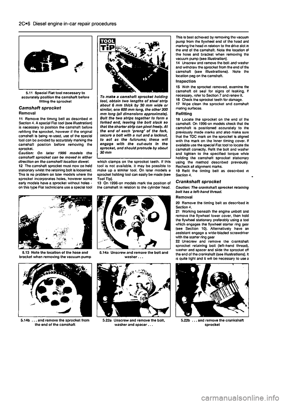
Camshaft sprocket Removal 11 Remove the timing belt as descnbed in Section 4. A special Rat tool (see illustration) is necessary to position the camshaft before refitting the sprocket, however il the original camshafl Is being re-used, use of the special tool can be ovoided by accurately marking the camshaft position before removing the sprocket. Caution: On later 1996 models the camshaft sprocket can be moved In either direction on tho camshaft location dowel. 12 The camshaft sprocket must now oe held stationary whilst the retaining bolt is loosened. This is no problem on later models where the sprocket incorporates holes, however some early models have a sprocket without holes • on this type Fiat technicians use a special tool
V*— r^r
To make a camshaft sprocket holding tool, obtain two lengths of steel strip about 6 mm thick by 30 mm wide or simllar, one 600 mm long, the other 200 mm long (all dimensions approximate). Bolt the two strips together to form a forked end, leaving tho bolt slack so that the shorter strip can pivot freely. At the end of each 'prong' of the fork, secure a bolt with a nut and a locknut, to act as the futcrums; theso will engage with the cut'Outs In the sprocket, and should protrude by about 30 mm
which clamps on the sprockot teeth. If this tool is not available, it may be possible to make up a similar tool. On later models a sprocket holding tool can easily be made (see Toot Tip). 13 On 1996-on models mark the position of the camshaft in relation to the cylinder head.
5.14a Unscrew and remove the bolt and washer...
This is best achieved by removing tho vacuum pump from the flywheel end of the head and marking the head in relation to Ihe drive slot in ihe end of the camshaft. Note the location of the hose and bracket when removing tha vacuum pump (seo illustration). 14 Unscrew and remove tho boll and v/ashof and withdraw the sprocket from the end of tha camshaft (see Illustrations). Note tha location peg on the camshafl. Inspection 15 With the sprocket removed, examine the camshaft oil seal for signs of leaking. If necessary, rater to Section 7 and renew it 16 Check the sprocket teeth for damage. 17 Wipe clean the sprocket and camshaft mating surfaces-Refitting 18 Locate the sprocket on the end of the camshaft. On J996-on models chock that the camshaft is positioned accurately to tho previously made marks and also make sura thai the TOC mark on Ihe sprocket Is aligned with the mark on the Inner timing cover. If avoiiablo use the special Fiat toot to locate the camshaft correctly. Rofil the bolt and washer and tighten lo the specified torque while holding the camshalt sprocket stationary using the method descnbed previously. Recheck all alignment marks. 19 Refit the timing belt as described in Section 4.
Crankshaft sprocket Caution: The crankshaft sprockot retaining bolt has a left-hand thread. Removal 20 Remove the timing belt as described in Section 4. 21 Working beneath the engine unbolt and remove the flywheel lower cover, than hold the flywheel stationary preferably using a tool which engages the flywheel starter ring gear (see Section 10). Alternatively have an assistant engage a wide-bladed screwdriver with the starter ring gear 22 Unscrew and remove (he crankshaft sprocket retaining bolt (left-hand thread), washer and spacer and slide the sprocket off the end of the crankshaft (see illustrations). It is quite tight and il will be necessary to use a
5.14b ... and remove the sprocket from tho end of the camshaft 5.22a Unscrew and remove the bolt, washer and spacer... 5.22b ... and remove the crankshaft sprocket
Page 79 of 225
Diesel engine in-car repair procedures
2C*11
5.31c ... followed by the Woodruff key
rocking motion to remove It, Note that the sprocket Is located by an integral key. Inspection 23 With the sprocket removed, examine the crankshaft oil seal for signs of leaking. If necessary, refer to Section 8 and renew it. 24 Check the sprocket teeth for damage. Also check the key and if necessary renew it. 25 Wipe clean the sprocket and crankshaft mating surfaces. Refitting 26 Slide the sprocket onto the crankshaft and engage the key with the slot In the crankshaft. 27 Refit the bolt, washer and spacer and tighten the bolt to the specified torque white holding the crankshaft stationary using the method described in paragraph 21. 28 Refit the timing belt as described in Sectton 4.
6.3a Support bracket positions on the camshaft cover
5.31a Use a puller to release the sprocket from the injection pump shaft
5.35 Tightening the injection pump sprocket bolt
Injection pump sprocket
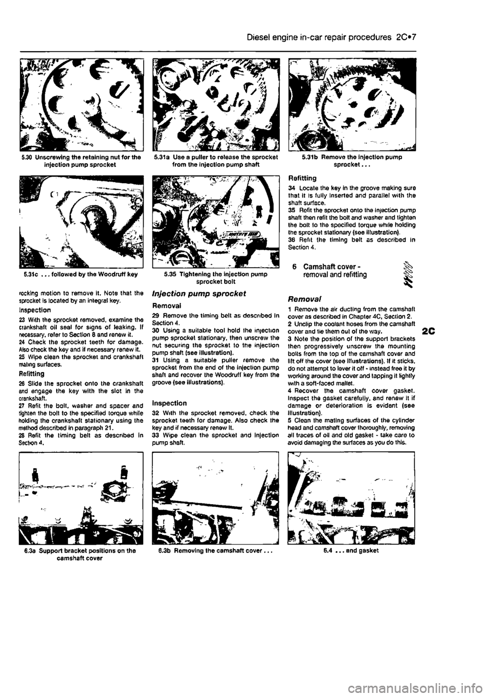
Removal 29 Remove the timing belt as described In Section 4. 30 Using a suitable tool hold Ihe injection pump sprocket stationary, then unscrew the nut securing the sprocket to the injection pump shaft (see illustration). 31 Using a suitable puller remove the sprocket from the end of the injection pump shaft and recover the Woodruff key from the groove (see illustrations),
Inspection 32 With the sprocket removed, check the sprocket teeth for damage. Also check the key and if necessary renew It. 33 Wipe clean the sprocket and injection pump shaft,
5.31b Removo tho injection pump sprocket...
Refitting 34 Locate the key in the groove making sure that it is fully Inserted and parallel with the shaft surface. 35 Refit the sprocket onto the Injection pump shaft then refit the bolt and washer and tighten the bolt to the specified torque while holding the sprocket stationary (soe illustration). 36 Refit the timing belt as described In Section 4,
6 Camshaft cover -removal and refitting ^
Removal 1 Remove the air ducting from the camshaft cover as described in Chapter 40, Section 2. 2 Unclip the coolant hoses from the camshaft cover and tie them out of tho way. 3 Note the position of the support brackets then progressively unscrew the mounting bolts from the top of the camshaft cover and lilt off the cover (see illustrations). If it sticks, do not attempt to lever it off • instead free it by working around the cover and tapping it lightly with a soft-faced mallet. 4 Recover the camshaft cover gasket. Inspect the gasket carefully, and renew It if damage or deterioration is evident (see illustration). 5 Clean the mating surfaces of the cylinder head and camshaft cover thoroughly, removing all traces of oil and old gasket • take oaro to avoid damaging the surfaces as you do this.
6.4 ... and gasket
Page 80 of 225
2C*2 Diesel engine in-car repair procedures
Refitting 6 Locate a new gasket on the cylinder head and make sure tt Is correctly seated. 7 Lower the cover onto the gasket making sure the gasket Is not displaced, 8 Insert the mounting bolts and tighten them securely In a progressive sequence. Position Ihe support brackets as noted during removal. 9 Clip ihe coolant hoses in position then refil the air ducting.
7 Camshaft oil seal -renewal
8 Crankshaft oil seals -renswal I
9 Cylinder head -
removal
and refitting
1 Remove the timing belt and camshaft sprocket as descnbed in Sections 4 and 5. 2 Using a suitable hooked instrument, remove tho oil seal from the cylinder head taking care nol to damage the surface of the camshafl. Alternatively drill a small hole In tho oil seal and Insert a self-topping screw - the seal can then be removed by pulling on the screw with a pair of pliers. 3 Clean the seating In the cylinder head and tho end of the camshaft To prevent damage to the new oil seal as It is being fitted, wrap some adhesive tape around the end ol the camshaft and lightJy oil it. 4 Dip tho new ail s«al In oil then locate it over Ihe camshaft making sure that the sealing lips are facing inwards. 5 Using a suitable tubular drift, drive the oil seal squarely into the cylinder h*ad. Remove the adhesive tap© 6 Refit the camshaft sprocket and timing belt with reference to Sections 6 and 4.
Front (right-hand side) oil seal t The front oil seal is located in the oil pump casing on the front of the crankshaft. Remove the timing belt as described in Section 4 and the crankshaft sprocket as described in Section 5, 2 Using a suitable hooked instrument, remove the oil seal from the oil pump casing taking care not to damage the surface of the crankshaft. Alternatively drill a small hole In the oil soal and insert a self-tapping screw - the seal can then be removed by pulling on the screw with a pair of pliers. 3 Clean the seating in the oH pump and the surface of the crankshaft. To prevent damage to the new off seal as It Is being fitted, wrap some adhesive tape around the end of tha crankshaft and lightly oil it. 4 Oip the new oii seal In oil then otter it up to the oil pump casing making sure that the sealing Hps are facing inwards,
8.Ba Rear oil soal and housing
5 Using a suitable tubular drift, driva the oil sea! squarely into the casing. Remove the adhesive tape. 6 Refit the crankshaft sprocket and timing belt with reference to Sections 5 and 4.
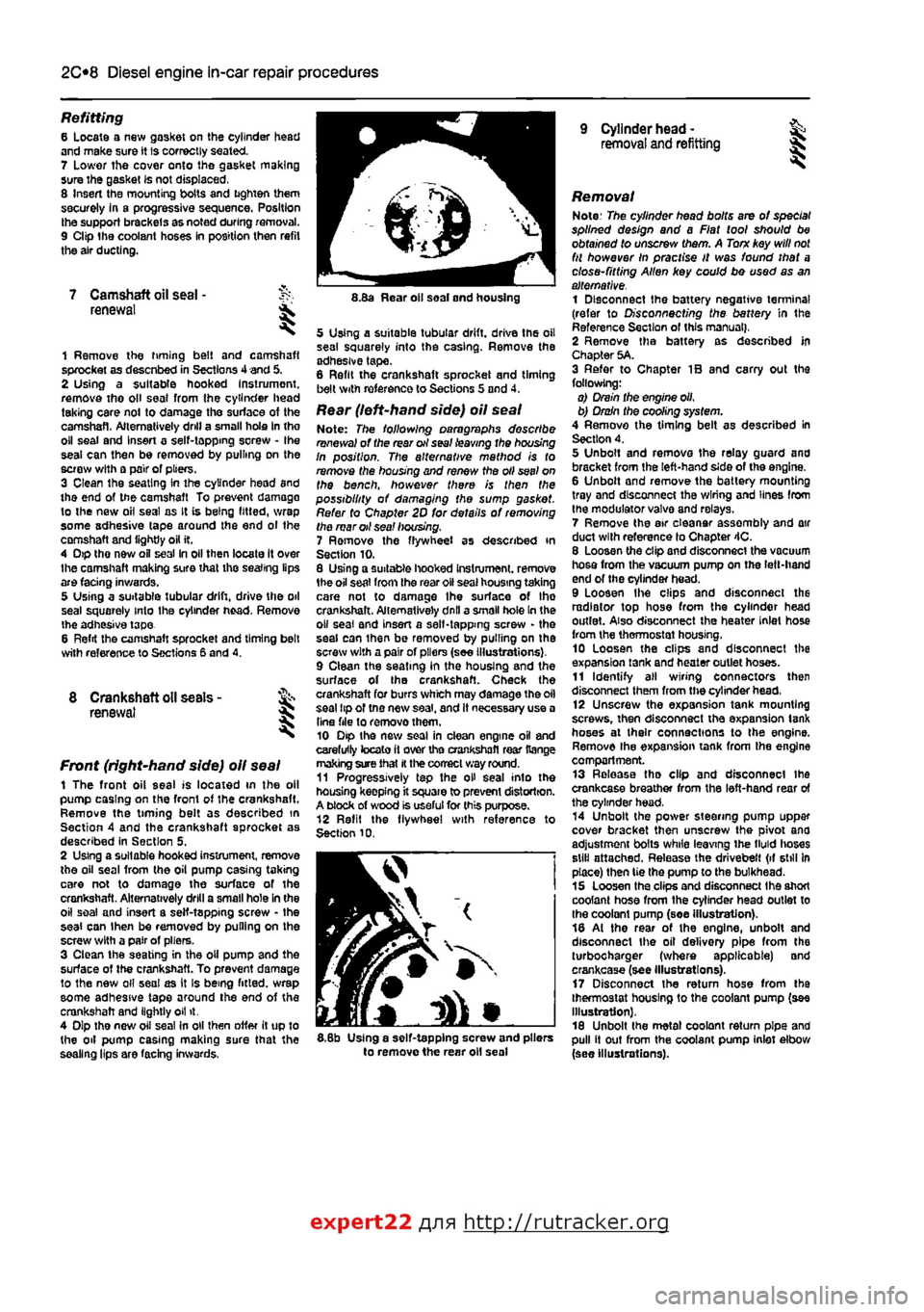
Rear (left-hand side) oil seal Note: The following paragraphs describe renewal of the rear oil seal leaving the housing In position. The alternative mathod is to remove the housing and renew the oil seel on the bench, however there is then the possibility of damaging the sump gasket. Refer to Chapter 2D for details of removing the mar oil sea! housing. 7 Ramove the flywheel as described in Section 10. 8 Using a suitable hooked Instrument. remove 1he oil seat from the roar oil seal housing taking care not to damage Ihe surface of Ihe crankshaft. Alternatively dnll a small hole In the o» seal and insert a self-tapping screw - the seal can ihan be removed by pulling on the screw with a pair of pliers (see Illustrations), 9 Clean the seating in the housing and the surface of the crankshaft. Check the crankshaft for burrs which may damage the oil seal tip of tno new saal, and It necessary use a Una file to removothem. 10 Dip the new soal in clean engine oil and carefully tocato it over tho crankshafl rear Range making sure that
H
the correct way round. 11 Progressively tap the oH seal into the housing keepfng it square to prevent distortion. A block of wood is useful for this purpose. 12 Refit the flywheel with reference to Section 10.
I
5.8b Using a self-tapping screw and pliers to remove the rear oil seal
Removal Note: The cylinder head bolts are of special splined design and a Fiat tool should be obtained to unscrew them. A Torn key will
not
fit however In practise It was found that a close-fitting Allen key could bo used as an alternative. 1 Disconnect the battery negative terminal (refer to Disconnecting the battery in the Reference Section of this manual), 2 Remove tha battery as described In Chapter 5A. 3 Refer to Chapter IB and carry out the following: o) Drain the engine oil, b) Drain the cooling system. 4 Remove the timing belt as described in Section 4. 5 Unbolt and remova the relay guard and bracket from the left-hand side of the engine. 6 Unbolt and remove the battery mounting tray and disconnect the wiring and lines from the modulator valva and relays. 7 Remove the air eleanar assembly and air duct with reference lo Chapter 4C. 8 Loosen the clip and disconnect the vacuum hosa from the vacuum pump on the left-hand end of the cylinder head. 9 Loosen Ihe clips and disconnect the radiator top hose from the cylinder head outlet. Also disconnect the heater inlet hose from the thermostat housing, 10 Loosen the clips and disconnect the expansion tank and heater outlet hoses. 11 Identify all wiring connectors then disconnect them from the cylinder head, 12 Unscrew the expansion tank mounting screws, then disconnect tha expansion tank hoses at their connections to the engine. Remove the expansion tank from tha engine compartment. 13 Release tha clip and disconnect ihe crankcase breather from the left-hand rear of the cylinder head. 14 Unbolt the power steering pump uppar cover bracket then unscrew the pivot ana adjustment bolts while leaving ihe tMd lioses still attached. Release the drivebelt (if still In place) then tie the pump to the bulkhead. 15 Loosen tha clips and disconnect Ihe short coolant hose from the cylinder head outlet to the coolant pump (soe illustration). 18 At the rear of the engine, unbolt and disconnect the oil delivery pipe from the turbocharger (where applicable) and crankcase (see Illustrations). 17 Disconnect the return hose from tha thermostat housing to the coolant pump (see Illustration), 18 Unbolt the metal coolant return pipe and pull it out from the coolant pump inlet elbow (see Illustrations).
expert22 flna http://rutracker.org
Page 81 of 225
Diesel engine in-car repair procedures
2C*11
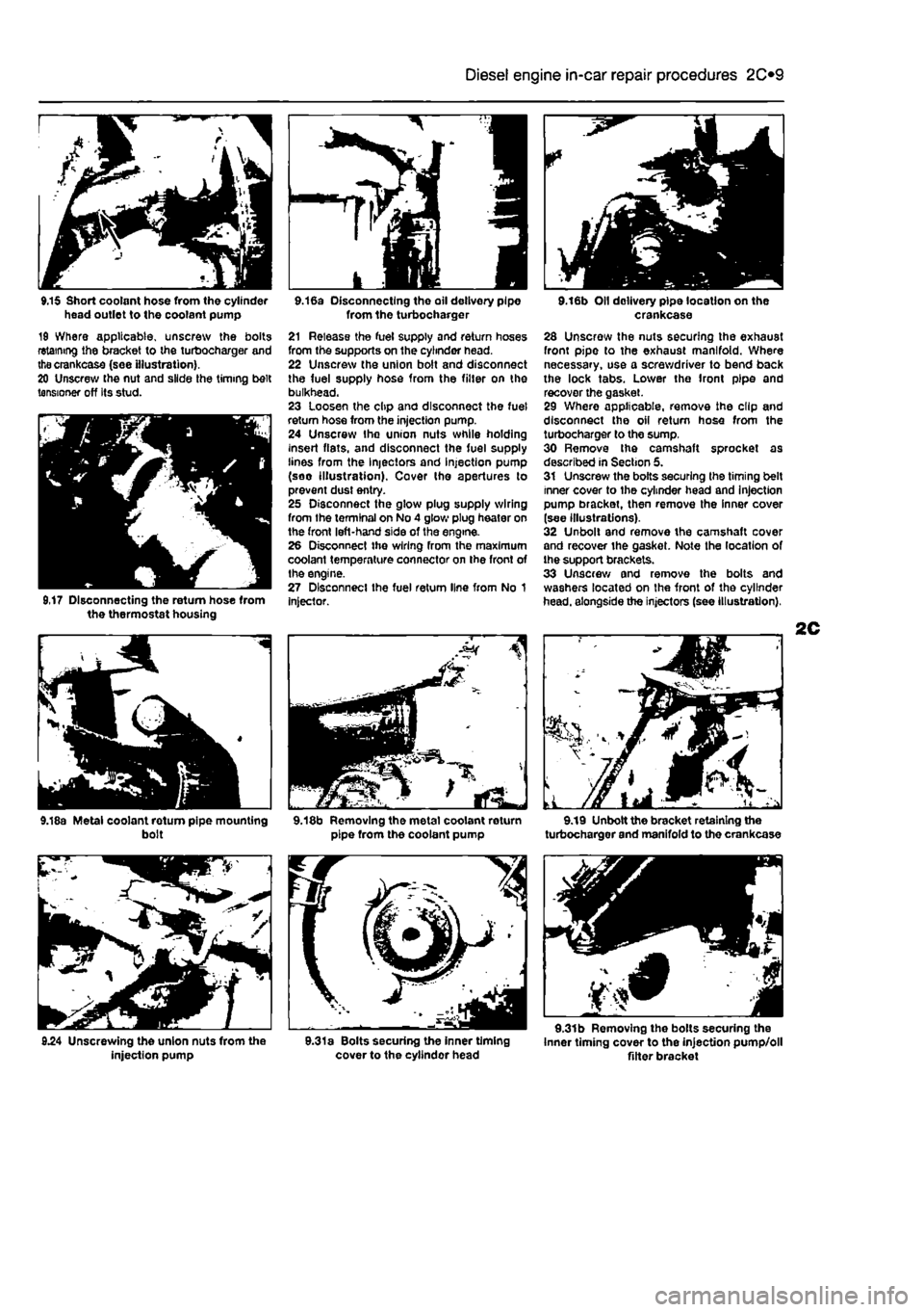
9.15 Short coolant hose from the cylinder head outlet to the coolant pump 19 Where applicable, unscrew the bolts retaining the bracket to the turbocharger and thecrankcase (see illustration). 20 Unscrew the nut and slide the timing belt tensioner off Its stud.
9,17 Disconnecting the return hose from the thermostat housing
9.18a Metal coolant rotum pipe mounting bolt
injection pump
9.16a Disconnecting the oil delivery pipe from the turbocharger 21 Release the fuel supply and return hoses from the supports on the cylinder head. 22 Unscrew the union bolt and disconnect the fuel supply hose from the filter on the bulkhead. 23 Loosen the clip and disconnect the fuel return hose from the injection pump. 24 Unscrew Ihe union nuts while holding insert fiats, and disconnect the fuel supply lines from the Injectors and injection pump (soo illustration). Cover tho apertures to prevent dust entry. 25 Disconnect the glow plug supply wiring from the terminal on No 4 glow plug heater on the front left-hand side of the engine. 26 Disconnect the wiring from the maximum coolant temperature connector on the front of the engine. 27 Disconnect the fuel return line from No 1 Injector.
9.18b Removing the metal coolant return pipe from the coolant pump
9.31a Bolts securing the inner timing cover to the cyllndor head
9.16b Oil delivery pipe location on the crankcase 28 Unscrew the nuts securing the exhaust front pipe to the exhaust manifold. Where necessary, use a screwdriver to bend back the lock tabs. Lower the front pipe and recover the gasket. 29 Where applicable, remove the clip and disconnect the oil return hose from the turbocharger to the sump. 30 Remove the camshaft sprocket as described in Section 5. 31 Unscrew the bolts securing the timing belt inner cover to the cylinder head and injection pump bracket, then remove the inner cover (see illustrations). 32 Unbolt and remove the camshaft cover and recover the gasket. Note the location of the support brackets. 33 Unscrew and remove the bolts and washers located on the front of the cylinder head, alongside the injectors (see illustration),
9.19 Unbolt the bracket retaining the turbocharger and manifold to the crankcase
9.31b Removing the bolts securing the Inner timing cover to the injection pump/oll Alter bracket
Page 82 of 225
2C*2 Diesel engine in-car repair procedures
9.31c Removing the inner timing cover
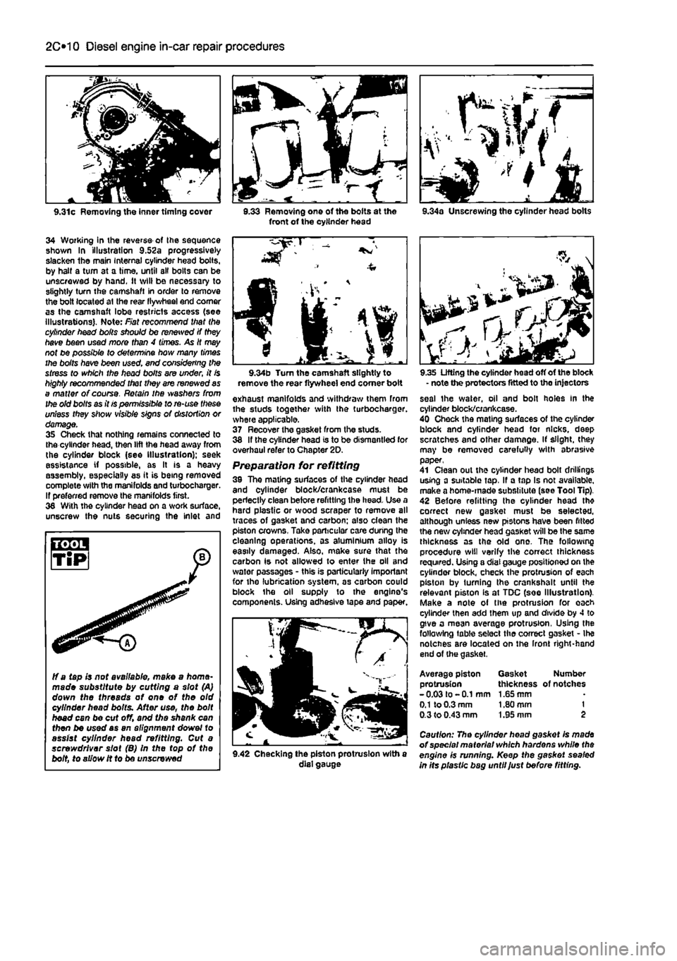
34 Working in ihe reverse of Ihe sequence shown In illustration 9.52a progressively slacken the main Internal cylinder head bolts, by halt a turn at a time, until all bolts can be unscrewed by hand. It will be necessary to slightly turn the camshaft in order to remove the bolt located at the rear llywheel end comer as the camshaft lobe restricts access (see illustrations). Note: Fiat recommend that the cylinder head boils should be renewed if they have been used more than 4 times. As It may not be possible to determine how many times the bolts have been used. end considering the stress to which the head bolts are under, it is highly recommended that they are renewed as a matter of course. Retain ihe washers from the old bolts as it is permissible to re-use these unless they show visible signs of distortion or damage. 35 Check that nothing remains connected to the cylinder head, then lift the head away from the cylinder block (see Illustration); seek assistance if possible, as It is a heavy assembly, especially as it is being removed complete with the manifolds and turbochargar. If preferred remove the manifolds first. 36 With the cylinder head on a work surface, unscrew the nuts securing the inlet and
3.33 Removing one of the bolts at the front of the cylinder head 9.34a Unscrewing the cylinder head bolts
ff a tapis not available, make a home-made substitute by cutting a slot (A) down the threads of one of the old cylinder head bolts. After use, the bolt head can be cut off, and the shank can then be used as an alignment dowel to assist cylinder head refitting. Cut a screwdriver slot (B) In the top of the bolt, to allow it to be unscrewed
9.34b Turn the camshaft slightly to remove the rear flywheel end comer boit exhaust manifolds and withdraw them from the studs together with the turbocharger. where applicable. 37 Recover the gasket from the studs. 38 If the cylinder head is to be dismantled for overhaul refer to Chapter 2D. Preparation for refitting 39 The mating surfaces of the cylinder head and cylinder block/crankcase must be perfectly clean before refitting the head. Use a hard plastic or wood scraper to remove all traces of gasket and carbon; also dean the piston crowns, Take particular care during the cleaning operations, as aluminium alloy is easily damaged. Also, make sure that the carbon is not allowed to enter the oil and water passages - this is particularly important for the lubrication system, as carbon could block the oil supply to the engine's components. Using adhesive tape and paper.
9.42 Checking the piston protrusion with a dial gauge
9.35 Lifting the cylinder head off of the block - note the protectors fitted to the injectors seal the water, oil and bolt holes In the cylinder block/crankcase. 40 Check the mating surfaces of the cylinder block and cylinder head for nicks, deep scratches and other damage. If slight, (hey may be removed carefully with abrasive paper, 41 Clean out the cylinder head bolt drillings using a suitable tap, If a tap Is not available, make a home-made substitute (see Tool Tip). 42 Before refitting the cylinder head th* correct new gasket must be selected, although unless new pistons have been fitted the new cylinder head gasket will be the same thickness as the old one. The following procedure will verify the correct thickness required. Using a dial gauge positioned on the cylinder block, check the protrusion of each piston by turning the crankshalt until the relevant piston Is at TDC (see Illustration). Make a note of the protrusion for oach cylinder then add them up and divide by 4 to give a mean average protrusion, Using the following table select the correct gasket - Ihe notcnes are located on the Iront right-hand end of (he gasket.
Average piston Gasket Number protrusion thickness of notches -0.03 to -0.1 mm 1.65 mm
0.1
to 0.3 mm 1.80 mm 1 0.3 to 0.43 mm 1.95 mm 2
Caution: The cylinder head gasket Is made of special material which hardens while the engine is running. Keep the gasket sealed in Its plastic bag until Just before fitting.