dashboard FIAT PUNTO 2012 Owner handbook (in English)
[x] Cancel search | Manufacturer: FIAT, Model Year: 2012, Model line: PUNTO, Model: FIAT PUNTO 2012Pages: 219, PDF Size: 9.58 MB
Page 8 of 219
4
SAFETY
STARTING
AND DRIVING
WARNING
LIGHTS AND MESSAGES
IN AN
EMERGENCY
SERVICE
AND CARE
TECHNICAL
SPECIFICATIONS
INDEX
CONTROLS
AND DEVICESDASHBOARD ......................................................................\
5
SYMBOLS ........................................................................\
....... 6
THE FIAT C ODE SYSTEM ................................................. 6
THE KEYS ........................................................................\
...... 8
ALARM ........................................................................\
........... 10
IGNITION .......................................................................\
...... 12
INSTRUMENT PANEL ........................................................ 13
INSTRUMENTS .................................................................... 14
DIGITAL DISPLAY ............................................................... 16
MULTIFUNCTION DISPLAY ............................................ 21
TRIP COMPUTER ................................................................ 30
FRONT SEATS ..................................................................... 32
REAR S EATS ........................................................................\
.. 33
HEAD RESTRAINTS ........................................................... 34
STEERING WHEEL .............................................................. 35
MIRRORS .......................................................................\
........ 35
HEATING AND VENTILATION SYSTE M .................... 37
MANUAL CLIMATE CONTROL SYSTE M .................... 41
EXTERIOR LIGHTS ............................................................. 47
WINDOW CLEAN ING ..................................................... 49
CEILING COURTESY LIGHTS ......................................... 51
CONTROLS .......................................................................\
. 53
FUEL CUT-OFF SYSTEM ................................................... 55 INTERIOR FI
TTINGS ........................................................... 56
DOORS ........................................................................\
.......... 60
ELECTRIC WINDOW OPENING ................................. 63
BOOT ........................................................................\
............. 65
BONNET .......................................................................\
........ 68
ROOF RACK/SKI RACK .................................................... 69
HEADLIGHTS ....................................................................... 70
ABS SYSTE M ......................................................................\
... 72
ESP SYSTEM ......................................................................\
.... 73
EOBD SYSTEM ..................................................................... 76
“DUAL DRIVE” ELECTRIC POWER
STEERING SYSTEM ............................................................. 77
START&STOP SYSTEM ...................................................... 79
SYSTÈME GEAR SHIFT INDICATOR ............................. 84
SOUND SYSTE M ................................................................. 85
ABILITY TO INSTALL A PORTABLE
NAVIGATION SYSTEM ..................................................... 86
ACCESSORIES PURCHASED BY THE OWNER ......... 86
REFEULLING THE CAR ..................................................... 88
PROTECTING THE ENVIRONMENT ........................... 89
C
C
O
O
N
N
T
T
R
R
O
O
L
L
S
S
A
A
N
N
D
D
D
D
E
E
V
V
I
I
C
C
E
E
S
S
001-032 PUNTO POP 1ed EN.qxd 3-10-2011 11:43 Pagina 4
Page 9 of 219
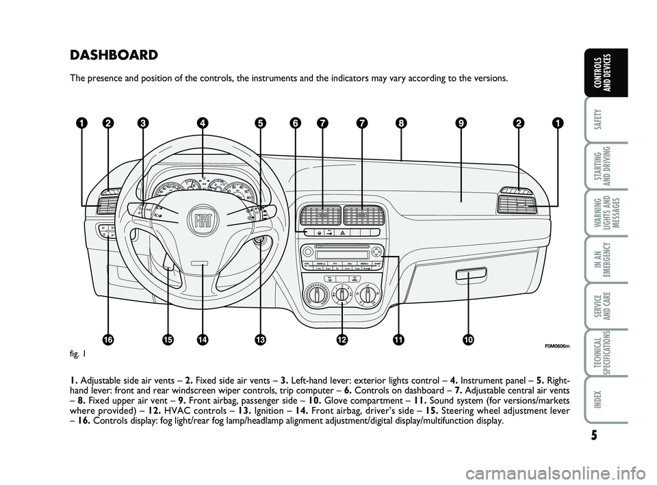
DASHBOARD
The presence and position of the controls, the instruments and the indic\
ators may vary according to the versions.
1.Adjustable side air vents – 2.Fixed side air vents – 3.Left-hand lever: exterior lights control – 4. Instrument panel – 5.Right-
hand lever: front and rear windscreen wiper controls, trip computer –\
6. Controls on dashboard – 7.Adjustable central air vents
– 8. Fixed upper air vent – 9.Front airbag, passenger side – 10. Glove compartment – 11.Sound system (for versions/markets
where provided) – 12. HVAC controls – 13.Ignition – 14.Front airbag, driver’s side – 15. Steering wheel adjustment lever
– 16. Controls display: fog light/rear fog lamp/headlamp alignment adjustment/\
digital display/multifunction display.
5
SAFETY
STARTING
AND DRIVING
WARNING
LIGHTS AND MESSAGES
IN AN
EMERGENCY
SERVICE
AND CARE
TECHNICAL
SPECIFICATIONS
INDEX
CONTROLS
AND DEVICES
F0M0606mfig. 1
001-032 PUNTO POP 1ed EN.qxd 3-10-2011 11:43 Pagina 5
Page 13 of 219
9
SAFETY
STARTING
AND DRIVING
WARNING
LIGHTS AND MESSAGES
IN AN
EMERGENCY
SERVICE
AND CARE
TECHNICAL
SPECIFICATIONS
INDEX
CONTROLS
AND DEVICES
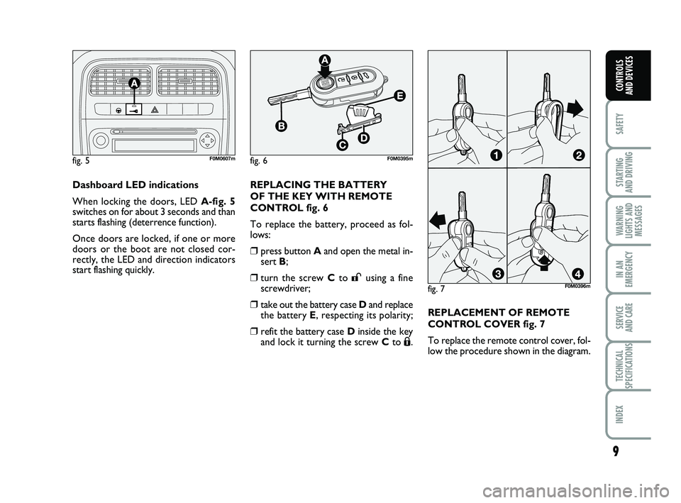
Dashboard LED indications
When locking the doors, LED A-fig. 5
switches on for about 3 seconds and than
starts flashing (deterrence function).
Once doors are locked, if one or more
doors or the boot are not closed cor-
rectly, the LED and direction indicators
start flashing quickly.
fig. 5F0M0607m
fig. 7
fig. 6F0M0395m
F0M0396m
REPLACING THE BATTERY
OF THE KEY WITH REMOTE
CONTROL fig. 6
To replace the battery, proceed as fol-
lows:
❒press button Aand open the metal in-
sert B;
❒turn the screw Cto :using a fine
screwdriver;
❒take out the battery case Dand replace
the battery E , respecting its polarity;
❒refit the battery case Dinside the key
and lock it turning the screw C to Á.REPLACEMENT OF REMOTE
CONTROL COVER fig. 7
To replace the remote control cover, fol-
low the procedure shown in the diagram.
001-032 PUNTO POP 1ed EN.qxd 10-10-2011 10:24 Pagina 9
Page 43 of 219
39
SAFETY
STARTING
AND DRIVING
WARNING
LIGHTS AND MESSAGES
IN AN
EMERGENCY
SERVICE
AND CARE
TECHNICAL
SPECIFICATIONS
INDEX
CONTROLS
AND DEVICES
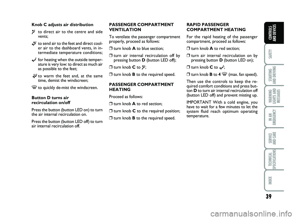
Knob C adjusts air distribution
¶to direct air to the centre and side
vents;
ßto send air to the feet and direct cool-
er air to the dashboard vents, in in-
termediate temperature conditions;
©for heating when the outside temper-
ature is very low: to direct as much air
as possible to the feet;
®to warm the feet and, at the same
time, demist the windscreen;
-to quickly de-mist the windscreen.
Button D turns air
recirculation on/off
Press the button (button LED on) to turn
the air internal recirculation on.
Press the button (button LED off) to turn
air internal recirculation off. RAPID PASSENGER
COMPARTMENT HEATING
For the rapid heating of the passenger
compartment, proceed as follows:
❒turn knob A
to red section;
❒turn air internal recirculation on by
pressing button D(button LED on);
❒turn knob C to ©;
❒turn knob Bto 4 -(max. fan speed).
Then use the controls to keep the re-
quired comfort conditions and press but-
ton Dto turn air internal recirculation off
(button LED off) and prevent misting up.
IMPORTANT With a cold engine, you
have to wait for a few minutes to let the
system fluid reach optimum operating
temperature.
PASSENGER COMPARTMENT
VENTILATION
To ventilate the passenger compartment
properly, proceed as follows:
❒turn knob A
to blue section;
❒turn air internal recirculation off by
pressing button D(button LED off);
❒turn knob C to ¶;
❒turn knob Bto the required speed.
PASSENGER COMPARTMENT
HEATING
Proceed as follows:
❒turn knob A to red section;
❒turn knob C to the required position;
❒turn knob Bto the required speed.
033-069 PUNTO POP 1ed EN 30-09-2011 10:17 Pagina 39
Page 46 of 219
42
SAFETY
STARTING
AND DRIVING
WARNING
LIGHTS AND MESSAGES
IN AN
EMERGENCY
SERVICE
AND CARE
TECHNICAL
SPECIFICATIONS
INDEX
CONTROLS
AND DEVICES
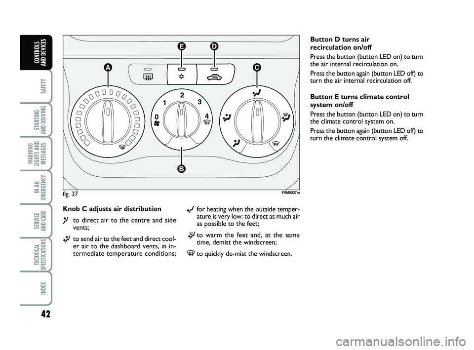
Knob C adjusts air distribution
¶to direct air to the centre and side
vents;
ßto send air to the feet and direct cool-
er air to the dashboard vents, in in-
termediate temperature conditions; Button D turns air
recirculation on/off
Press the button (button LED on) to turn
the air internal recirculation on.
Press the button again (button LED off) to
turn the air internal recirculation off.
Button E turns climate control
system on/off
Press the button (button LED on) to turn
the climate control system on.
Press the button again (button LED off) to
turn the climate control system off.
fig. 37F0M0037m
©for heating when the outside temper-
ature is very low: to direct as much air
as possible to the feet;
®to warm the feet and, at the same
time, demist the windscreen;
-to quickly de-mist the windscreen.
033-069 PUNTO POP 1ed EN 30-09-2011 10:17 Pagina 42
Page 51 of 219
47
SAFETY
STARTING
AND DRIVING
WARNING
LIGHTS AND MESSAGES
IN AN
EMERGENCY
SERVICE
AND CARE
TECHNICAL
SPECIFICATIONS
INDEX
CONTROLS
AND DEVICES
EXTERIOR LIGHTS
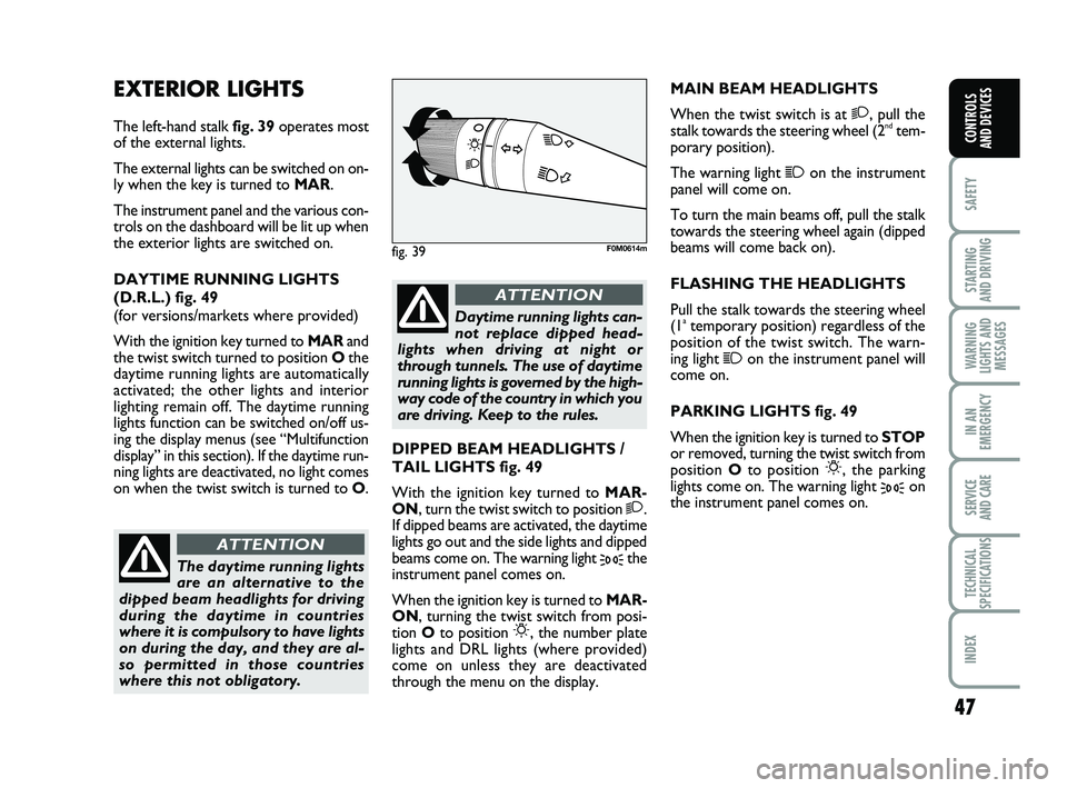
The left-hand stalk fig. 39operates most
of the external lights.
The external lights can be switched on on-
ly when the key is turned to MAR.
The instrument panel and the various con-
trols on the dashboard will be lit up when
the exterior lights are switched on.
DAYTIME RUNNING LIGHTS
(D.R.L.) fig. 49
(for versions/markets where provided)
With the ignition key turned to MARand
the twist switch turned to position Othe
daytime running lights are automatically
activated; the other lights and interior
lighting remain off. The daytime running
lights function can be switched on/off us-
ing the display menus (see “Multifunction
display” in this section). If the daytime run-
ning lights are deactivated, no light comes
on when the twist switch is turned to O. MAIN BEAM HEADLIGHTS
When the twist switch is at 2, pull the
stalk towards the steering wheel (2ndtem-
porary position).
The warning light
1on the instrument
panel will come on.
To turn the main beams off, pull the stalk
towards the steering wheel again (dipped
beams will come back on).
FLASHING THE HEADLIGHTS
Pull the stalk towards the steering wheel
(1
atemporary position) regardless of the
position of the twist switch. The warn-
ing light
1on the instrument panel will
come on.
PARKING LIGHTS fig. 49
When the ignition key is turned to STOP
or removed, turning the twist switch from
position Oto position
6, the parking
lights come on. The warning light
3on
the instrument panel comes on.
fig. 39F0M0614m
DIPPED BEAM HEADLIGHTS /
TAIL LIGHTS fig. 49
With the ignition key turned to MAR-
ON, turn the twist switch to position
2.
If dipped beams are activated, the daytime
lights go out and the side lights and dipped
beams come on. The warning light
3the
instrument panel comes on.
When the ignition key is turned to MAR-
ON, turning the twist switch from posi-
tion Oto position
6, the number plate
lights and DRL lights (where provided)
come on unless they are deactivated
through the menu on the display.
The daytime running lights
are an alternative to the
dipped beam headlights for driving
during the daytime in countries
where it is compulsory to have lights
on during the day, and they are al-
so permitted in those countries
where this not obligatory.
ATTENTION
Daytime running lights can-
not replace dipped head-
lights when driving at night or
through tunnels. The use of daytime
running lights is governed by the high-
way code of the country in which you
are driving. Keep to the rules.
ATTENTION
033-069 PUNTO POP 1ed EN 30-09-2011 10:17 Pagina 47
Page 54 of 219
50
SAFETY
STARTING
AND DRIVING
WARNING
LIGHTS AND MESSAGES
IN AN
EMERGENCY
SERVICE
AND CARE
TECHNICAL
SPECIFICATIONS
INDEX
CONTROLS
AND DEVICES
REAR WINDOW WASHER/WIPER
fig. 41
This can work only when the key is turned
to MAR.
The function stops when the stalk is re-
leased.
Turning the twist switch from Oto
'will
operate the rear window wiper as follows:
❒intermittent operation if the wind-
screen wiper is off;
❒synchronised operation (but with half-
stroke frequency) when the windscreen
wiper is on;
❒continuous operation with reverse en-
gaged and function on. Do not use the rear window
wiper to remove layers of
snow or ice. In such condi-
tions, the rear window wiper
may be subjected to excessive stress,
prompting intervention from the mo-
tor protection which prevents opera-
tion for a few seconds. If operation is
not restored, even after turning the key
and restarting the engine, go to a Fiat
Dealership.
The rear window wiper will run in con-
tinuous mode when the windscreen wiper
is on and reverse gear is engaged.
Pushing the stalk towards the dashboard
(temporary position) will activate the rear
window washer jet.
Keeping the stalk pushed for more than
half a second will also activate the rear
window wiper.
Smart wash function is activated when the
stalk is released, like for the windscreen
wiper.
033-069 PUNTO POP 1ed EN 30-09-2011 10:17 Pagina 50
Page 60 of 219
56
SAFETY
STARTING
AND DRIVING
WARNING
LIGHTS AND MESSAGES
IN AN
EMERGENCY
SERVICE
AND CARE
TECHNICAL
SPECIFICATIONS
INDEX
CONTROLS
AND DEVICES
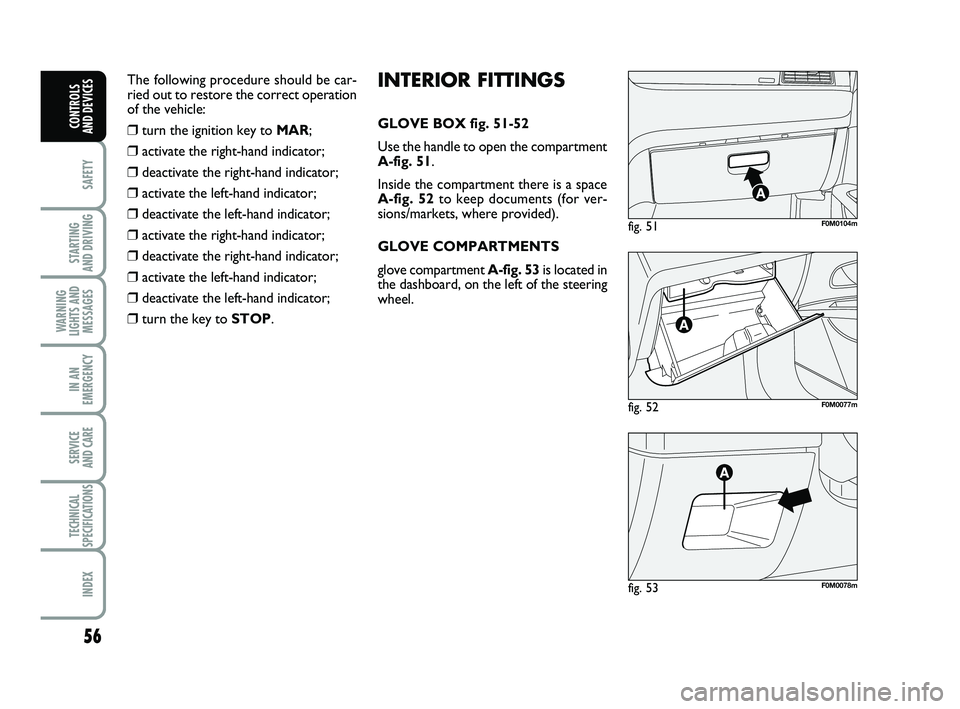
fig. 52F0M0077m
fig. 51F0M0104m
fig. 53F0M0078m
INTERIOR FITTINGS
GLOVE BOX fig. 51-52
Use the handle to open the compartment
A-fig. 51.
Inside the compartment there is a space
A-fig. 52 to keep documents (for ver-
sions/markets, where provided).
GLOVE COMPARTMENTS
glove compartment A-fig. 53 is located in
the dashboard, on the left of the steering
wheel.
The following procedure should be car-
ried out to restore the correct operation
of the vehicle:❒turn the ignition key to
MAR;
❒activate the right-hand indicator;
❒deactivate the right-hand indicator;
❒activate the left-hand indicator;
❒deactivate the left-hand indicator;
❒activate the right-hand indicator;
❒deactivate the right-hand indicator;
❒activate the left-hand indicator;
❒deactivate the left-hand indicator;
❒turn the key to STOP.
033-069 PUNTO POP 1ed EN 30-09-2011 10:17 Pagina 56
Page 61 of 219
57
SAFETY
STARTING
AND DRIVING
WARNING
LIGHTS AND MESSAGES
IN AN
EMERGENCY
SERVICE
AND CARE
TECHNICAL
SPECIFICATIONS
INDEX
CONTROLS
AND DEVICES
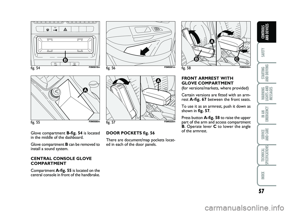
DOOR POCKETS fig. 56
There are document/map pockets locat-
ed in each of the door panels. FRONT ARMREST WITH
GLOVE COMPARTMENT
(for versions/markets, where provided)
Certain versions are fitted with an arm-
rest
A-fig. 67 between the front seats.
To use it as an armrest, push it down as
shown in fig. 57.
Press button A-fig. 58 to raise the upper
part of the arm and access compartment
B . Operate lever C to lower the angle
of the armrest.
fig. 54F0M0619m
fig. 55F0M0080mfig. 57F0M0225m
fig. 58F0M0245mfig. 56F0M0081m
Glove compartment B-fig. 54 is located
in the middle of the dashboard.
Glove compartment Bcan be removed to
install a sound system.
CENTRAL CONSOLE GLOVE
COMPARTMENT
Compartment A-fig. 55is located on the
central console in front of the handbrake.
033-069 PUNTO POP 1ed EN 30-09-2011 10:17 Pagina 57
Page 65 of 219
61
SAFETY
STARTING
AND DRIVING
WARNING
LIGHTS AND MESSAGES
IN AN
EMERGENCY
SERVICE
AND CARE
TECHNICAL
SPECIFICATIONS
INDEX
CONTROLS
AND DEVICES
Following the locking of the doors using:
❒remote control;
❒door catch;
it will not be possible to unlock them by
pressing button
A-fig. 72located on the
dashboard.
IMPORTANT With central locking on,
pulling the internal handle of one of the
front doors will unlock that door. Indi-
vidual doors can be unlocked by pulling
the internal handle of one of the rear
doors.
If a power supply is not present (blown
fuse, battery disconnected, etc.) it is, how-
ever, possible to lock the doors manually.
After exceeding a speed of 20 km/h, all
doors will be centrally locked automati-
cally if the setup menu function has been
selected (see paragraph “Multifunction dis-
play” in this section).
Once the dead lock system is
engaged, it is impossible to
open the doors from inside the vehi-
cle. Before getting out of the car,
please therefore check that there is
no-one left on board. If the remote
control battery is flat, the system can
be disengaged only by inserting the
key in either of the door locks as de-
scribed previously: in this case the de-
vice remains active only for the rear
doors.
DEAD LOCK
(for versions/markets, where provided)
This safety device inhibits the operation of:
❒interior handles;
❒locking/unlocking button
A-fig. 72;
thereby preventing the opening of the
doors from inside the passenger com-
partment if there has been a break-in at-
tempt (e.g. a window has been broken).
The dead lock device therefore offers the
best possible protection against break-in
attempts. We recommend engaging it
whenever the vehicle is parked and left un-
attended. Device activation
The dead lock device is automatically ac-
tivated on every door by briefly pressing
the remote control button
Áfig. 70
twice.
Device activation is indicated by 3 flashes
of the direction indicators and a flash of
the LED on button
A-fig. 72on the dash-
board.
If one or more of the doors is not closed
correctly, the dead lock device will not ac-
tivate, thus preventing a person from get-
ting stuck inside the passenger compart-
ment by entering the car through, and
then closing, the open door.
Device deactivation
The system is disabled automatically on
every door in the following cases:
❒when opening the driver’s door using
the key without remote control;
❒when unlocking doors using the remote
control;
❒when turning the ignition key to MAR.
WARNING
033-069 PUNTO POP 1ed EN 30-09-2011 10:17 Pagina 61