sensor FIAT PUNTO EVO 2010 1.G User Guide
[x] Cancel search | Manufacturer: FIAT, Model Year: 2010, Model line: PUNTO EVO, Model: FIAT PUNTO EVO 2010 1.GPages: 270, PDF Size: 8.34 MB
Page 164 of 270
163
Degraded engine oil
(only Multijet versions with DPF)
The warning light will flash and a specific message will ap-
pear on the display (for versions/markets where provid-
ed). The warning light may flash in the following ways, de-
pending on the version:
– for 1 minute every two hours;
– for 3 minute cycles with the warning light off for inter-
vals of 5 seconds until oil is changed.
After the initial warning, each time the engine is started
up, the warning light will continue to flash in the same ways
as described above, until the oil is changed. A specific mes-
sage will appear on the display (for versions/markets where
provided) in addition to the warning light.
If the warning light flashes, this does not mean that the car
is defective, but simply informs the driver that it is now
necessary to change the oil as a result of regular vehicle
use.
KNOWING
YOUR
VEHICLE
SAFETY
STARTING
AND DRIVING
WARNING LIGHTS
AND MESSAGES
IN AN
EMERGENCY
SERVICING
AND CARE
TECHNICAL
SPECIFICATIONS
CONTENTS
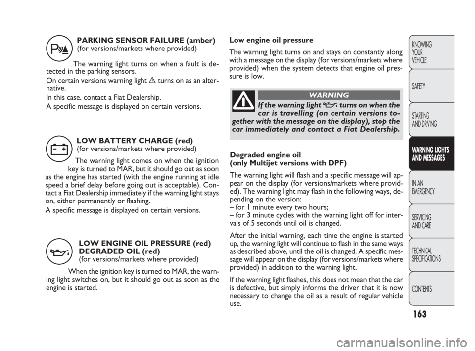
LOW BATTERY CHARGE (red)
(for versions/markets where provided)
The warning light comes on when the ignition
key is turned to MAR, but it should go out as soon
as the engine has started (with the engine running at idle
speed a brief delay before going out is acceptable). Con-
tact a Fiat Dealership immediately if the warning light stays
on, either permanently or flashing.
A specific message is displayed on certain versions.
w
LOW ENGINE OIL PRESSURE (red)
DEGRADED OIL (red)
(for versions/markets where provided)
When the ignition key is turned to MAR, the warn-
ing light switches on, but it should go out as soon as the
engine is started.
v
If the warning light vturns on when the
car is travelling (on certain versions to-
gether with the message on the display), stop the
car immediately and contact a Fiat Dealership.
WARNING
PARKING SENSOR FAILURE (amber)
(for versions/markets where provided)
The warning light turns on when a fault is de-
tected in the parking sensors.
On certain versions warning light èturns on as an alter-
native.
In this case, contact a Fiat Dealership.
A specific message is displayed on certain versions.
t
Low engine oil pressure
The warning light turns on and stays on constantly along
with a message on the display (for versions/markets where
provided) when the system detects that engine oil pres-
sure is low.
161-174 PUNTO FL EN 4ed 18-01-2010 12:27 Pagina 163
Page 170 of 270
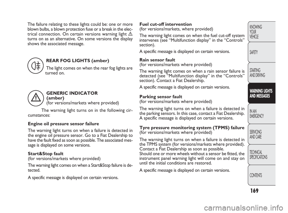
GENERIC INDICATOR
(amber)
(for versions/markets where provided)
The warning light turns on in the following cir-
cumstances:
Engine oil pressure sensor failure
The warning light turns on when a failure is detected in
the engine oil pressure sensor. Go to a Fiat Dealership to
have the fault fixed as soon as possible. The associated mes-
sage is displayed on some versions.
Start&Stop fault
(for versions/markets where provided)
The warning light comes on when a Start&Stop failure is de-
tected.
A specific message is displayed on certain versions.
169
KNOWING
YOUR
VEHICLE
SAFETY
STARTING
AND DRIVING
WARNING LIGHTS
AND MESSAGES
IN AN
EMERGENCY
SERVICING
AND CARE
TECHNICAL
SPECIFICATIONS
CONTENTS
REAR FOG LIGHTS (amber)
The light comes on when the rear fog lights are
turned on.
4
Fuel cut-off intervention
(for versions/markets, where provided)
The warning light comes on when the fuel cut-off system
intervenes (see “Multifunction display” in the “Controls”
section).
A specific message is displayed on certain versions.
Rain sensor fault
(for versions/markets where provided)
The warning light comes on when a rain sensor failure is
detected (see “Multifunction display” in the “Controls”
section). Contact a Fiat Dealership.
A specific message is displayed on certain versions.
Parking sensor fault
(for versions/markets where provided)
The warning light turns on when a failure is detected in
the parking sensors. In this case, contact a Fiat Dealership.
A specific message is displayed on certain versions.
Tyre pressure monitoring system (TPMS) failure
(for versions/markets where provided)
The warning light turns on when a failure is detected in
the TPMS system (for versions/markets where provided).
Contact a Fiat Dealership as soon as possible.
Should one or more wheels without a sensor be fitted, the
instrument panel warning light will come on and stay on
until the initial conditions are restored.
A specific message is displayed on certain versions.
è
The failure relating to these lights could be: one or more
blown bulbs, a blown protection fuse or a break in the elec-
trical connection. On certain versions warning light è
turns on as an alternative. On some versions the display
shows the associated message.
161-174 PUNTO FL EN 4ed 18-01-2010 12:27 Pagina 169
Page 204 of 270
203
KNOWING
YOUR
VEHICLE
SAFETY
STARTING
AND DRIVING
WARNING LIGHTS
AND MESSAGES
IN AN
EMERGENCY
SERVICING
AND CARE
TECHNICAL
SPECIFICATIONS
CONTENTS
7.5
7.5
5
5
10
5
20
20
20
20
5
5
7.5 1
8
13
2
5
11
4
6
14
7
12
3
10
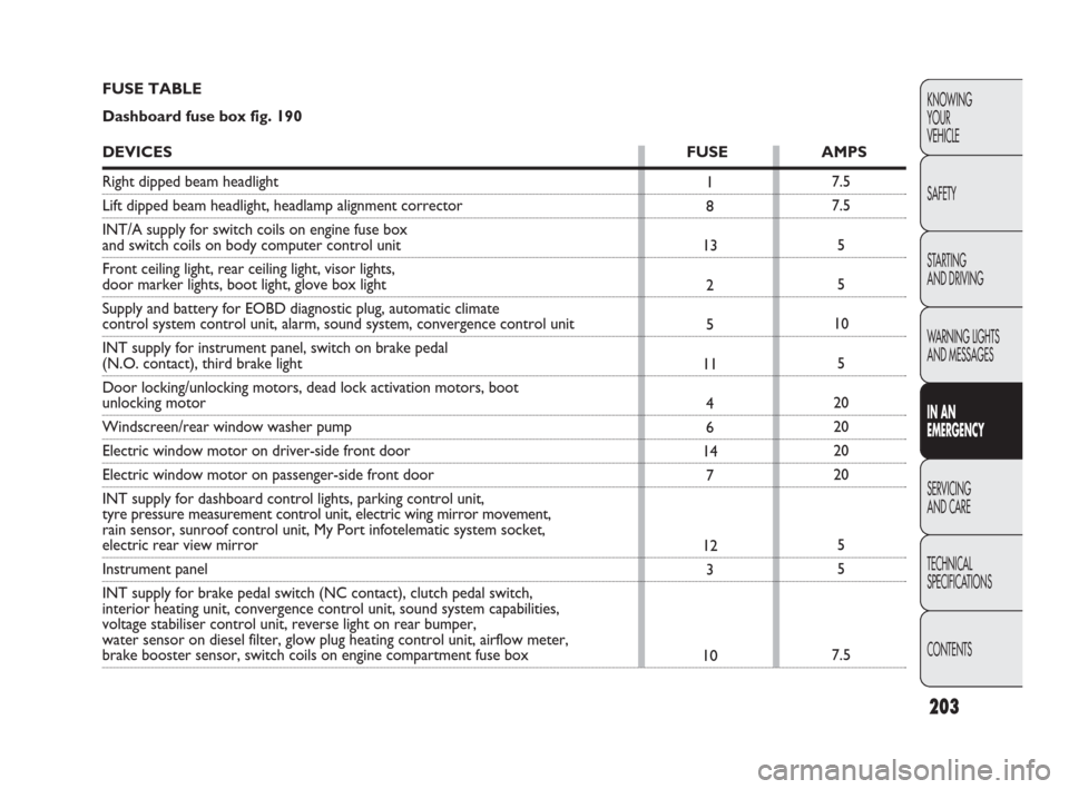
FUSE TABLE
Dashboard fuse box fig. 190
DEVICESFUSE AMPS
Right dipped beam headlight
Lift dipped beam headlight, headlamp alignment corrector
INT/A supply for switch coils on engine fuse box
and switch coils on body computer control unit
Front ceiling light, rear ceiling light, visor lights,
door marker lights, boot light, glove box light
Supply and battery for EOBD diagnostic plug, automatic climate
control system control unit, alarm, sound system, convergence control unit
INT supply for instrument panel, switch on brake pedal
(N.O. contact), third brake light
Door locking/unlocking motors, dead lock activation motors, boot
unlocking motor
Windscreen/rear window washer pump
Electric window motor on driver-side front door
Electric window motor on passenger-side front door
INT supply for dashboard control lights, parking control unit,
tyre pressure measurement control unit, electric wing mirror movement,
rain sensor, sunroof control unit, My Port infotelematic system socket,
electric rear view mirror
Instrument panel
INT supply for brake pedal switch (NC contact), clutch pedal switch,
interior heating unit, convergence control unit, sound system capabilities,
voltage stabiliser control unit, reverse light on rear bumper,
water sensor on diesel filter, glow plug heating control unit, airflow meter,
brake booster sensor, switch coils on engine compartment fuse box
175-210 PUNTO FL EN 4ed 20-01-2010 15:09 Pagina 203
Page 205 of 270
09
10
14
15
19
20
21
30
84
85
86
87
8820
10
15
30
7.5
30
15
15
7.5
–
15
5
7.5
204
KNOWING
YOUR
VEHICLE
SAFETY
STARTING
AND DRIVING
WARNING LIGHTS
AND MESSAGES
IN AN
EMERGENCY
SERVICING
AND CARE
TECHNICAL
SPECIFICATIONS
CONTENTS
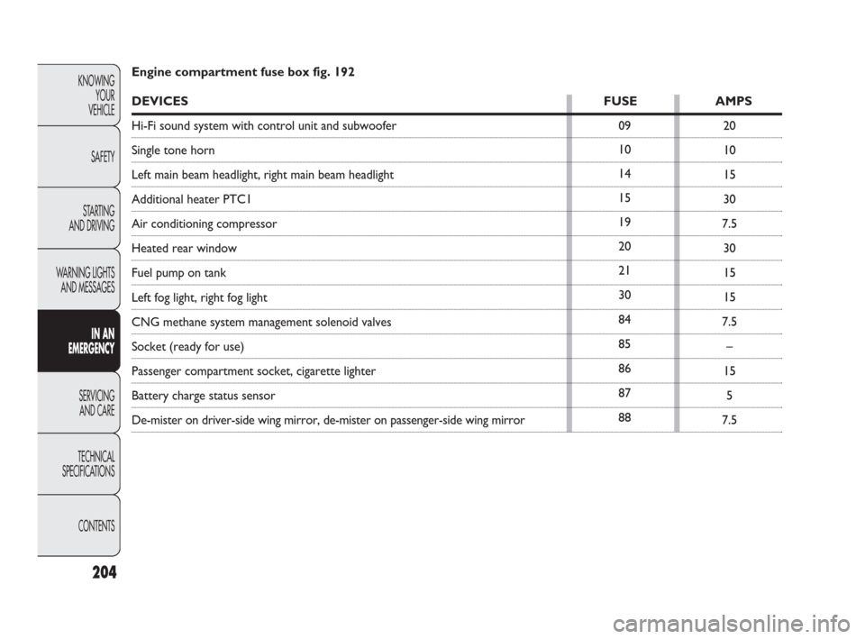
Engine compartment fuse box fig. 192
DEVICESFUSE AMPS
Hi-Fi sound system with control unit and subwoofer
Single tone horn
Left main beam headlight, right main beam headlight
Additional heater PTC1
Air conditioning compressor
Heated rear window
Fuel pump on tank
Left fog light, right fog light
CNG methane system management solenoid valves
Socket (ready for use)
Passenger compartment socket, cigarette lighter
Battery charge status sensor
De-mister on driver-side wing mirror, de-mister on passenger-side wing mirror
175-210 PUNTO FL EN 4ed 20-01-2010 15:09 Pagina 204
Page 207 of 270
206
KNOWING
YOUR
VEHICLE
SAFETY
STARTING
AND DRIVING
WARNING LIGHTS
AND MESSAGES
IN AN
EMERGENCY
SERVICING
AND CARE
TECHNICAL
SPECIFICATIONS
CONTENTS
RECHARGING THE BATTERY
IMPORTANT The battery recharging procedure is pro-
vided for information purposes only. You are recom-
mended to go to a Fiat Dealership to have this operation
performed.
We recommend recharging the battery slowly for ap-
proximately 24 hours at low amperage. Rapid charging with
high currents could damage the battery.
VERSIONS WITHOUT Start&Stop SYSTEM
(for versions/markets, where provided)
Charge the battery as follows:
❒disconnect the battery negative terminal;
❒connect the charger leads to the battery terminals, ob-
serving the polarity;
❒turn on the charger;
❒when you have finished, turn the charger off before dis-
connecting the battery;
❒reconnect battery negative terminal.
VERSIONS WITH Start&Stop SYSTEM
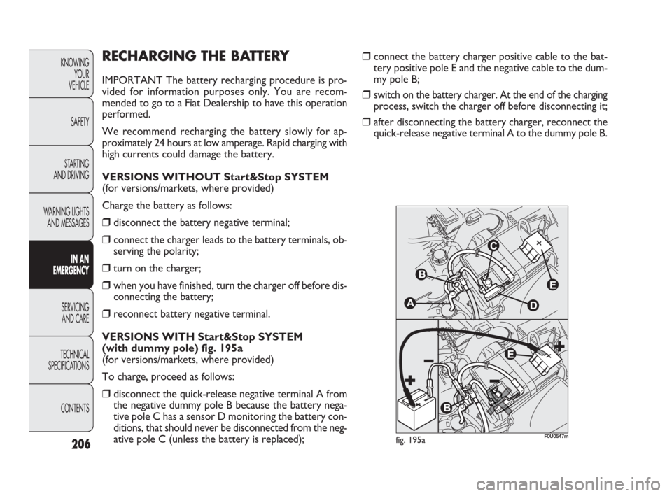
(with dummy pole) fig. 195a
(for versions/markets, where provided)
To charge, proceed as follows:
❒disconnect the quick-release negative terminal A from
the negative dummy pole B because the battery nega-
tive pole C has a sensor D monitoring the battery con-
ditions, that should never be disconnected from the neg-
ative pole C (unless the battery is replaced);
❒connect the battery charger positive cable to the bat-
tery positive pole E and the negative cable to the dum-
my pole B;
❒switch on the battery charger. At the end of the charging
process, switch the charger off before disconnecting it;
❒after disconnecting the battery charger, reconnect the
quick-release negative terminal A to the dummy pole B.
fig. 195aF0U0547m
175-210 PUNTO FL EN 4ed 20-01-2010 15:10 Pagina 206
Page 208 of 270
207
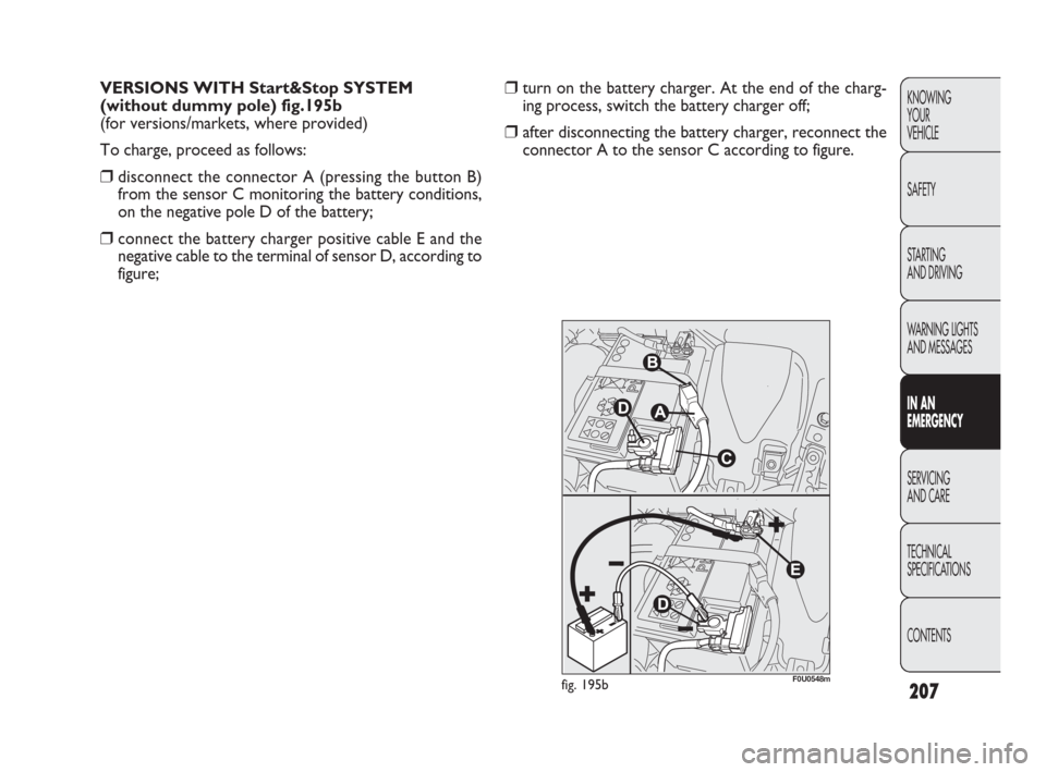
❒turn on the battery charger. At the end of the charg-
ing process, switch the battery charger off;
❒after disconnecting the battery charger, reconnect the
connector A to the sensor C according to figure. VERSIONS WITH Start&Stop SYSTEM
(without dummy pole) fig.195b
(for versions/markets, where provided)
To charge, proceed as follows:
❒disconnect the connector A (pressing the button B)
from the sensor C monitoring the battery conditions,
on the negative pole D of the battery;
❒connect the battery charger positive cable E and the
negative cable to the terminal of sensor D, according to
figure;
KNOWING
YOUR
VEHICLE
SAFETY
STARTING
AND DRIVING
WARNING LIGHTS
AND MESSAGES
IN AN
EMERGENCY
SERVICING
AND CARE
TECHNICAL
SPECIFICATIONS
CONTENTS
fig. 195bF0U0548m
175-210 PUNTO FL EN 4ed 20-01-2010 15:10 Pagina 207
Page 263 of 270
262
KNOWING
YOUR
VEHICLE
SAFETY
STARTING
AND DRIVING
WARNING LIGHTS
AND MESSAGES
IN AN
EMERGENCY
SERVICING
AND CARE
TECHNICAL
SPECIFICATIONS
CONTENTS
Installing electrical/electronic
devices ................................................ 124
– radio transmitters
and mobile phones ...................... 125
Installing the tow hook ...................... 157
Instrument panel ...................13-266-267
Interior lighting ................................... 68
Interiors (cleaning) ............................. 233
Internal equipment ............................. 74
Internal features .................................. 74
Isofix (child seat)
– capacity for installing child
seats ................................................ 138
– suitability for the child seats ...... 140
Jack
– usage ............................................... 178
– warnings ......................................... 177
Keys ...................................................... 5
– key with remote control ............ 6
– key without remote control ..... 9
– opening/closing doors remotely ... 6
– requesting additional remote
control keys .................................. 8
– replacing remote control
battery ............................................ 8
Knowing your vehicle.................. 3
Lights
(controls to switch on) ............ 61-71
Load limiters ........................................ 131
Long periods of inactivity .................. 160
Lubricant specifications ..........251-252Main beam headlights
– bulb replacement ......................... 190
– switching on .................................. 61
Main beam headlights
– bulb replacement ......................... 190
– flashing ............................................ 61
– switching on .................................. 61
Manual climate control ...................... 52
Maximum speeds ................................ 247
Mirrors
– rear-view ....................................... 44
– wing ................................................ 45
MSR system ......................................... 108
Multifunctional display ....................... 23
– setup menu .................................. 26
Nozzles
– windscreen/rear window/
headlamp washer ......................... 230
Number plate lights
– bulb replacement ......................... 194
Odometer ............................................ 15
On-board computer (trip) ................ 37
On-board instruments (panel) .......... 13
P
aintwork (maintenance) ................. 232
– bodywork colour plate ............... 236
Paintwork plate ................................... 236
ParafluUP
– checking levels and topping up ... 222
– specifications ................................. 252
Parking sensors ................................... 120
Particulate filter (DPF) ....................... 128Performance ........................................ 247
Pollen filter ........................................... 225
Protecting the environment ............. 127
– particulate filter (DPF) ................ 128
Protecting the environment ............. 127
Punctures
– changing a wheel .......................... 176
– Fix& Go automatic quick tyre
repair kit ........................................ 181
– general information ..................... 176
Quick tyre repair kit (Fix&Go) ....... 181
Radio transmitters and mobile
phones ................................................ 125
Raising the car
– with the jack ................................. 177
– with the lift arms .......................... 207
– with the workshop lift ................ 208
Rear ceiling lights ................................ 68
– bulb replacement ......................... 196
Rear fog light ....................................... 72
– bulb replacement ......................... 194
– switching on .................................. 72
Rear light clusters
– bulb replacement ......................... 193
Rear seats
– cleaning .......................................... 234
– headrests ....................................... 43
Rear window washer ......................... 65
– activating ........................................ 65
– checking levels and topping up ... 252
– nozzle ............................................. 231
Rear window wiper
– activating ........................................ 65
259-268 PUNTO FL EN 4ed 18-01-2010 12:29 Pagina 262